Leaks in a chemical process industries (CPI) facility can run the gamut from creating a costly waste to prefacing a catastrophic failure.. They can be an annoyance, by creating pools of liquid on concrete that can become a possible slipping hazard and housekeeping problem, or a leak that can emit toxic vapors, causing various degrees of harm to personnel. In some cases a leak may be a simple housekeeping issue that goes into the books as a footnote indicating that a repair should be made when resources are available. In other cases it can become a violation of regulatory compliance with statutory consequences, not to mention a risk to personnel safety and the possible loss of capital assets.
Understanding the mechanisms by which leaks can occur and prioritizing piping systems to be checked at specific intervals based on a few simple factors is not only a pragmatic approach to the preventive maintenance of piping systems, but is part of a CPI’s regulatory compliance. This includes compliance under both the U.S. Environmental Protection Agency (EPA) Clean Air Act (CAA; 40CFR Parts 50 to 52) and the Resource Conservation and Recovery Act (RCRA; 40CFR Parts 260 to 299). We will get into more detail with these regulations, as well as the leak detection and repair (LDAR) requirement within the above mentioned regulations, as we move through this discussion.
When discussing anything to do with government regulations, the terminology quickly turns into an alphabet soup of acronyms. The box on the right lists, for easy reference, the titles and acronyms that will be used in this discussion.
Leak mechanisms
Eliminating the potential for leaks is an integral part of the design process that takes place at the very onset of facility design. It is woven into the basic precept of the piping codes because it is such an elemental and essential component in the process of designing a safe and dependable piping system.
Piping systems, as referred to here, include pipe, valves and other inline components, as well as the equipment needed to hold, move and process chemicals. Why then, if we comply with codes and standards, and adhere to recommended industry practices, do we have to concern ourselves with leaks? Quite pointedly it is because much of what we do in design is theoretical, such as material selection for compatibility, and because in reality, in-process conditions and circumstances do not always perform as expected.
Whether due to human error or mechanical deficiencies, leaks are a mechanism by which a contained fluid finds a point of least resistance and, given time and circumstances, breaches its containment. What we look into, somewhat briefly, are two general means by which leaks can occur; namely corrosion and mechanical joint deficiencies.
Corrosion. Corrosion allowance (CA) is used as an applied factor in calculating, among other things, wall thickness in pipe and pressure vessels. The CA value assigned to a material is theoretical and predicated on four essential variables: material compatibility with the fluid, containment pressure, temperature of the fluid and velocity of the fluid. What the determination of a CA provides, given those variables, is a reasonable guess at a uniform rate of corrosion. And given that, an anticipated loss of material can be assumed over the theoretical lifecycle of a pipeline or vessel. It allows a reasonable amount of material to be added into the equation, along with mechanical allowances and a mill tolerance in performing wall thickness calculations. The problem is that beyond the design, engineering, and construction phase of building a facility, the in-service reality of corrosion can be very different.
Corrosion, in the majority of cases, does not occur in a uniform manner. It will most frequently occur in localized areas in the form of pits, as erosion at high-impingement areas, as corrosion under insulation, at heat-affected zones (HAZ) where welding was improperly performed, causing a localized change to the mechanical or chemical properties of the material, and in many other instances in which unforeseen circumstances create the potential for corrosion and the opportunity for leaks in the pipe itself or in a vessel wall. Because of that incongruity, corrosion is an anomaly that, in reality, cannot wholly be predicted.
Corrosion-rate values found in various published resources on the topic of material compatibility are based on static testing in which a material coupon is typically set in a vile containing a corrosive chemical. This can be done at varying temperatures and in varying concentrations. After a period of time, the coupon is pulled and the rate of corrosion is assessed. That is a simplification of the process, but you get the point. When a material of construction (MOC) and a potentially corrosive chemical come together in operational conditions, the theoretical foundation upon which the material selection was based becomes an ongoing realtime assessment. This means that due diligence needs to be paid to examining areas of particular concern, depending on operating conditions, such as circumferential pipe welds for cracking, high-impingement areas for abnormal loss of wall thickness, hydrogen stress-corrosion cracking (HSCC), and others.
The LDAR program does not specify the need to check anything other than mechanical joints for potential leaks. Monitoring pipe and vessel walls, particularly at welds that come in contact with corrosive chemicals, is a safety consideration and practical economics. Performing cursory examinations for such points of corrosion where the potential exists should be made part of any quality assurance or quality control (QA/QC) and preventive maintenance program.
Mechanical joints and open-ended pipe. Mechanical joints can include such joining methods as flanges, unions, threaded joints, valve bonnets, stem seals and clamp assemblies. It can also include pump, compressor and agitator seals. Other potential points of transient emissions include open-ended piping, such as drains, vents, and the discharge pipe from a pressure-relief device. Any of these joints or interfaces can be considered potential leak points and require both monitoring and record-keeping documentation in compliance with the EPA’s LDAR program.
Mechanical joints can leak due to improper assembly, insufficient or unequal load on all bolts, improperly selected gasket type, sufficient pressure or temperature swings that can cause bolts to exceed their elastic range (diminishing their compressive load on the joint), and an improperly performed “hot-bolting” procedure in which in-service bolts are replaced while the pipeline remains in service. “Hot bolting” is not a recommended procedure, but is nonetheless done on occasion.
Pump, compressor and agitator seals can develop leaks where shaft misalignment plays a part. If the shaft is not installed within recommended tolerances or if it becomes misaligned over time there is a good possibility the seal will begin to fail.
The LDAR program
Promulgated in 1970 and amended in 1977 and 1990, the Clean Air Act requires that manufacturers producing or handling VOCs develop and maintain an LDAR program in accordance with the requirements set forth under the Clean Air Act. This program monitors and documents leaks of VOCs in accordance with Method 21 — Determination of Volatile Organic Compound Leaks.
Table 1 provides a listing of key elements that should be contained in an LDAR program. Those elements are described as follows:
| Table 1. Elements of a Model LDAR Program | |
| Written LDAR compliance | First attempt at repair |
| Training | Delay of repair compliance assurance |
| LDAR audits | Electronic monitoring and storage of data |
| Contractor accountability | QA/QC of LDAR data |
| Internal leak definitions | Calibration/calibration drift assessment |
| Less frequent monitoring | Records maintenance |
Written LDAR compliance. Compile a written procedure declaring and defining regulatory requirements that pertain to your specific facility. This should include recordkeeping certifications; monitoring and repair procedures; name, title, and work description of each personnel assignment on the LDAR team; required procedures for compiling test data; and a listing of all process units subject to federal, state and local LDAR regulations.
Training. Assigned members of the LDAR team should have some experience base that includes work performed in or around the types of piping systems they will be testing and monitoring under the LDAR program. Their training should include familiarization with Method 21 and also training as to the correct procedure for how to examine the various interface connections they will be testing. They should also receive training on the test instrument they will be using and how to enter the test data in the proper manner. All of this needs to be described in the procedure.
LDAR audits. An internal audit team should be established to ensure that the program is being carried out on a routine basis in an efficient and comprehensive manner in accordance with the written procedures. A third-party audit team is brought in every few years to confirm that internal audits are being carried out in the proper manner and that all equipment that should be included in the monitoring is listed as such. It also ensures that the tests are being carried out properly and that the test results are entered properly.
Contractor accountability. When selecting an outside contractor to perform internal LDAR audits for a facility or when bringing in an outside contractor to inspect the work of the internal audit team, it is recommended that the contract be written in a manner that places appropriate responsibility on that contractor. In doing so there should be penalties described and assessed as a result of insufficient performance or inaccurate documentation of prescribed testing and documentation procedures. Expectations should be well defined and any deviation from those prescribed norms by a third-party contractor should constitute a breach of contract. In all fairness, both parties must understand exactley what those expectations are.
Internal leak definitions. Internal leak definitions are the maximum parts per million, by volume (ppmv) limits acceptable for valves, connectors and seals, as defined by the CAA regulation governing a facility. For example, a facility may be required to set an internal leak-definition limit of 500 ppm for valves and connectors in light liquid or gas/vapor fluid service and 2,000 ppm internal leak definition for pumps in light liquid or gas/vapor fluid service. “Light liquid” is defined as a fluid whose vapor pressure is greater than 0.044 psia at 68°F.
Less frequent monitoring. Under some regulations it is allowed that a longer period between testing is acceptable if a facility has consistently demonstrated good performance (as defined in the applicable regulation). For example, if a facility has consistently demonstrated good performance under monthly testing, then the frequency of testing could be adjusted to a quarterly test frequency.
First attempt at repair. Upon detection of a leak, most rules will require that a first attempt be made to repair the leak within five days of detection; if unsuccessful, any follow-up attempts need to be finalized within 15 days. Should the repair remain unsuccessful within the 15-day time period, the leak must be placed on a “delay of repair” list and a notation must be made for repair or component replacement during the next shutdown of which the leaking component is a part.
Delay of repair compliance assurance. Placing a repair item on the “delay of repair” list gives assurances that the item justifiably belongs on the list, that a plan exists to repair the item, and that parts are on hand to rectify the problem. It is suggested that any item being listed in the “delay of repair” list automatically generate a work order to perform the repair.
Electronic monitoring and storage of data. Entering leak-test data into an electronic database system will help in retrieving such data and in utilizing them in ways that help provide reports highlighting areas of greater concern to areas of lesser concern. Such information can help direct attention and resources away from areas of least concern, while mobilizing resources to areas of greater concern. This enables a much more efficient use of information and resources.
QA/QC of LDAR data. A well written LDAR program will include a QA/QC procedure defining the process by which it is assured that Method 21 is being adhered to, and that testing is being carried out in the proper manner and includes the proper equipment and components. This also includes the maintenance of proper documentation.
Calibration/calibration-drift assessment. LDAR monitoring equipment should be calibrated in accordance with Method 21. Calibration-drift assessment of LDAR monitoring equipment should be made at the end of each monitoring work shift using approximately 500 ppm of calibration gas. If, after the initial calibration, drift assessment shows a negative drift of more than 10% from the previous calibration, all components that were tested since the last calibration with a reading greater than 100 ppm should be re-tested. Re-test all pumps that were tested since the last calibration having a reading of greater than 500 ppm.
Records maintenance. Internal electronic record-keeping and reporting is an essential component to a well-implemented LDAR program. It is an indication to the NEIC that every effort is being made to comply with the regulations pertinent to a facility. It provides ready access to the personnel associated with the program, the test data, leak repair reports and so on.
Testing for leaks
Results, when using a leak detection monitor, are only as accurate as its calibration and the manner in which it is used. Calibration is discussed in the next section, “Method 21.” To use the monitor correctly, the auditor will need to place the nozzle or end of the probe as close as possible to the flange, threaded joint, or seal interface as follows:
• In the case of a flange joint test: 180 deg around perimeter of the flange joint at their interface
• In the case of a threaded joint test: 180 deg around perimeter of interface of the male/female fit-up
• If it is a coupling threaded at both ends, check both ends 180 deg around the perimeter
• If it is a threaded union, then check both ends and the body nut 180 deg around the perimeter
• In the case of a valve test:
• 180 deg around perimeter of all end connections if anything other than welded
• 180 deg around perimeter of body flange
• 180 deg around perimeter of body/bonnet interface
• 180 deg around perimeter of stem packing at stem
• In the case of a rotating equipment shaft seal test: 180 deg around the perimeter of the interface of the seal and the shaft
Method 21
Method 21, under 40 CFR Part 60, Appendix A, provides rules with respect to how VOCs are monitored and measured at potential leak points in a facility. Those potential leak points include, but are not limited to: valves, flanges and other connections; pumps and compressors; pressure-relief devices; process drains; open-ended valves; pump and compressor seals; degassing vents; accumulator vessel vents; agitator seals and access door seals. It also describes the required calibration process in setting up the monitoring device. Essentially any monitoring device may be used as long as it meets the requirements set forth in Method 21.
Cylinder gases used for calibrating a monitoring device need to be certified to be within an accuracy of 2% of their stated mixtures. It is recommended that any certification of this type be filed in either digital form or at the very least as a hard copy. There should also be a specified shelf life of the contents of the cylinder. If the shelf life is exceeded, the contents must be either re-analyzed or replaced.
Method 21 goes on to define how to test flanges and other joints, as well as pump and compressor seals and various other joints and interfaces with the potential for leaks. There are two gases required for calibration. One is referred to as a “zero gas,” defined as air with less than 10 ppmv (parts per million by volume) VOC. The other calibration gas, referred to as a reference gas, uses a specified reference compound in an air mixture. The concentration of the reference compound must approximately equal the leak definition specified in the regulation. The leak definition, as mentioned above, is the threshold standard pertinent to the governing regulation.
Monitoring devices
A portable VOC-monitoring device will typically be equipped with a rigid or flexible probe. The end of probe is placed at the leak interface of a joint, such as a flange, threaded connection or coupling, or at the interface of a pump, compressor, or agitator seal where it interfaces with the shaft. With its integral pump, the device, when switched on, will draw in a continuous sample of gas from the leak-interface area into the monitoring device. The instrument’s response or screening value is a relative measure of the sample’s concentration level. The screening value is detected and displayed in parts per million by volume, or if the instrument is capable and the degree of accuracy needed, in parts per billion by volume (ppbv).
The detection devices operate on a variety of detection principles. The most common are ionization, infrared absorption and combustion. Ionization detectors operate by ionizing a sample and then measuring the charge (that is, number of ions) produced.
Two methods of ionization currently used are flame ionization and photoionization. The flame ionization detector (FID) theoretically measures the total carbon content of the organic vapor sampled. The photoionization detector (PID) uses ultraviolet light to ionize the organic vapors. With both detectors, the response will vary with the functional group in the organic compounds. PIDs have been used to detect equipment leaks in process units in SOCMI facilities, particularly for compounds such as formaldehyde, aldehydes and other oxygenated chemicals that typically do not provide a satisfactory response on a FID-type unit.
Operation of the non-dispersive infrared (NDIR) detector is based on the principle that light absorption characteristics vary depending on the type of gas. Because of this, NDIR detection can be subject to interference due in large measure to such constituents as water vapor and CO2, which may absorb light at the same wavelength as the targeted compound. This type of detector is typically confined to the detection and measurement of single components. Because of that proclivity, good or bad, the wavelength at which a certain targeted compound absorbs infrared radiation, having a predetermined value, is preset for that specific wavelength through the use of optical filters. As an example, if the instrument was set to a wavelength of 3.4 micrometers, the device could detect and measure petroleum fractions, such as gasoline and naphtha.
The combustion-type analyzer is designed to measure either thermal conductivity of a gas or the heat produced as a result of combustion of the gas. Referred to as hot-wire detectors or catalytic oxidizers, combustion-type monitors are nonspecific for gas mixtures. If a gas is not readily combustible, similar in composition to formaldehyde and carbon tetrachloride, there may be a reduced response or no response at all.
Due to the variability in the sensitivity of the different monitoring devices, the screening value does not necessarily indicate the actual total concentration at the leak interface of the compound(s) being detected. The leak interface is the immediate vicinity of the joint being tested — the point at which the end of the probe is placed. Response factors (RFs), determined for each compound by testing or taken from reference sources, then correlate the actual concentration of a compound to that of the concentration detected by the monitoring device. As mentioned previously, the monitoring device must first be calibrated using a certified reference gas containing a known compound at a known concentration, such as that of methane and isobutylene. RFs at an actual concentration of 10,000 ppmv have been published by the EPA in a document entitled “Response Factors of VOC Analyzers Calibrated with Methane for Selected Organic Chemicals.”
Method 21 requires that any selected detector meet the following specifications:
• The VOC detector should respond to those organic compounds being processed (determined by the RF)
• Both the linear response range and the measurable range of the instrument for the VOC to be measured and the calibration gas must encompass the leak definition concentration specified in the regulation
• The scale of the analyzer meter must be readable to ±2.5% of the specified leak definition concentration
• The analyzer must be equipped with an electrically driven pump so that a continuous sample is provided at a nominal flowrate of between 0.1 and 3.0 L/min
• The analyzer must be intrinsically safe for operation in explosive atmospheres
• The analyzer must be equipped with a probe or probe extension not to exceed 0.25 in. outside diameter with a single end opening for sampling
Federal regulations
There are federal regulations that pertain to monitoring for VOCs and require the implementation of a formal LDAR program in concert with the rules of Method 21. There are other federal regulations that require the rules of Method 21, but do not require a formal LDAR program. Tables 2 and 3 list those various regulations.
It is the manufacturer’s responsibility to make the proper determination as to what regulations it needs to comply with. Those specific regulations, coupled with the Method 21 requirements, will define the LDAR program and help establish a comprehensive and detailed procedure.
| Table 2 – Federal Regulations That Require a Formal LDAR Program With Method 21 | ||
| 40 CFR | Regulation Title | |
| Part | Subpart | |
| 60 | VV | SOCMI VOC Equipment Leaks NSPS |
| 60 | DDD | Volatile Organic Compound (VOC) Emissions from the Polymer Manufacturing Industry |
| 60 | GGG | Petroleum Refinery VOC Equipment Leaks NSPS |
| 60 | KKK | Onshore Natural Gas Processing Plant VOC Equipment Leaks NSPS |
| 61 | J | National Emission Standard for Equipment Leaks (Fugitive Emission Sources) of Benzene |
| 61 | V | Equipment Leaks NESHAP |
| 63 | H | Organic HAP Equipment Leak NESHAP (HON) |
| 63 | I | Organic HAP Equipment Leak NESHAP for Certain Processes |
| 63 | J | Polyvinyl Chloride and Copolymers Production NESHAP |
| 63 | R | Gasoline Distribution Facilities (Bulk Gasoline Terminals and Pipeline Breakout Stations) |
| 63 | CC | Hazardous Air Pollutants from Petroleum Refineries |
| 63 | DD | Hazardous Air Pollutants from Off-Site Waste and Recovery Operations |
| 63 | SS | Closed Vent Systems, Control Devices, Recovery Devices and Routing to a Fuel Gas System or a Process |
| 63 | TT | Equipment Leaks – Control Level 1 |
| 63 | UU | Equipment Leaks – Control Level 2 |
| 63 | YY | Hazardous Air Pollutants for Source Categories: Generic Maximum Achievable Control Technology Standards |
| 63 | GGG | Pharmaceuticals Production |
| 63 | III | Hazardous Air Pollutants from Flexible Polyurethane Foam Production |
| 63 | MMM | Hazardous Air Pollutants for Pesticide Active Ingredient Production |
| 63 | FFFF | Hazardous Air Pollutants: Miscellaneous Organic Chemical Manufacturing |
| 63 | GGGGG | Hazardous Air Pollutants: Site Remediation |
| 63 | HHHHH | Hazardous Air Pollutants: Miscellaneous Coating Manufacturing |
| 65 | F | Consolidated Federal Air Rule — Equipment Leaks |
| 264 | BB | Equipment Leaks for Hazardous Waste TSDFs |
| 265 | BB | Equipment Leaks for Interim Status Hazardous Waste TSDFs |
| Table 3 – Federal Regulations that Require the Use of Method 21 But Not a Formal LDAR Program | ||
| 40 CFR | Regulation Title | |
| Part | Subpart | |
| 60 | XX | Bulk Gasoline Terminals |
| 60 | QQQ | VOC Emissions from Petroleum Refinery Wastewater Systems |
| 60 | WWW | Municipal Solid Waste Landfills |
| 61 | F | Vinyl Chloride |
| 61 | L | Benzene from Coke By-Products |
| 61 | BB | Benzene Transfer |
| 61 | FF | Benzene Waste Operations |
| 63 | G | Organic Hazardous Air Pollutants from SOCMI for Process Vents, Storage Vessels, Transfer Operations, and Wastewater |
| 63 | M | Perchloroethylene Standards for Dry Cleaning |
| 63 | S | Hazardous Air Pollutants from the Pulp and Paper Industry |
| 63 | Y | Marine Unloading Operations |
| 63 | EE | Magnetic Tape Manufacturing Operations |
| 63 | GG | Aerospace Manufacturing and Rework Facilities |
| 63 | HH | Hazardous Air Pollutants from Oil and Gas Production Facilities |
| 63 | OO | Tanks — Level 1 |
| 63 | PP | Containers |
| 63 | Surface Impoundments | |
| 63 | VV | Oil/Water, Organic/Water Separators |
| 63 | HHH | Hazardous Air Pollutants from Natural Gas Transmission and Storage |
| 63 | JJJ | Hazardous Air Pollutant Emissions: Group IV Polymers and Resins |
| 63 | VVV | Hazardous Air Pollutants: Publicly Owned Treatment Works |
| 65 | G | CFAR — Closed Vent Systems |
| 264 | AA | Owners and Operators of Hazardous Waste Treatment, Storage, and Disposal Facilities — Process Vents |
| 264 | CC | Owners and Operators of Hazardous Waste Treatment, Storage and Disposal Facilities — Tanks, Surface Impoundments, Containers |
| 265 | AA | Interim Standards for Owners and Operators of Hazardous Waste Treatment, Storage, and Disposal Facilities — Process Vents |
| 265 | CC | Interim Standards for Owners and Operators of Hazardous Waste Treatment, Storage, and Disposal Facilities — Tanks, Surface Impoundments, Containers |
| 270 | B | Hazardous Waste Permit Program — Permit Application |
| 270 | J | Hazardous Waste Permit Program — RCRA Standardized Permits for Storage Tanks and Treatment Units |
RCRA
The Solid Waste Disposal Act of 1965 was amended in 1976 to include the Resource Conservation and Recovery Act (RCRA), which encompassed the management of both hazardous waste and solid waste. Prompted further by an ever increasing concern of underground water contamination, this act was again amended in 1984 to address underground storage tanks (USTs) and associated underground piping under Subtitle I. This Amendment regulates the construction, monitoring, operating, reporting, record-keeping, and financial responsibility for USTs and associated underground piping that handle petroleum and hazardous fluids.
As of 2011, there were 590,104 active tanks and 1,768,193 closed tanks in existence in the U.S. Of the still active tanks, 70.9% were under significant operational compliance. This means that they were using the necessary equipment required by current UST regulations to prevent and detect releases and were performing the necessary UST system operation and maintenance.
In 1986, the Leaking Underground Storage Tank (LUST) Trust Fund was added to the RCRA program. The trust financing comes from a 0.1¢ tax on each gallon of motor fuel (gasoline, diesel or biofuel blend) sold nationwide. The LUST Trust Fund provides capital to do the following:
• Oversee cleanups of petroleum releases by responsible parties
• Enforce cleanups by recalcitrant parties
• Pay for cleanups at sites where the owner or operator is unknown, unwilling, or unable to respond, or those that require emergency action
• Conduct inspections and other release prevention activities
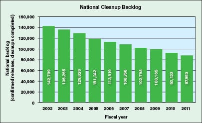
In Figure 1 the progress being made by the program can readily be seen. In 2002, RCRA was looking at 142,709 LUST sites — sites that were flagged for cleanup. Throughout the following nine years, 2002 through 2011, 54,726 of those sites were cleaned, leaving 87,983 still targeted for cleanup.
Within the RCRA program there are requirements that impact design, fabrication, construction, location, monitoring and operation of USTs and associated underground piping. The EPA has provided a number of sites on the internet that provide a great deal of information on the various CFR Parts. 40 CFR Part 260 contains all of the RCRA regulations governing hazardous waste identification, classification, generation, management and disposal.
Listed wastes are divided into the following group designations:
• The F group — non-specific source wastes found under 40 CFR 261.31
• The K group — source-specific wastes found under 40 CFR 261.32
• The P and U group — discarded commercial chemical products found under 40 CFR 261.33
Characteristic wastes, which exhibit one or more of four characteristics defined in 40 CFR Part 261 Subpart C are as follows:
• Ignitability, as described in 40 CFR 261.21
• Corrosivity, as described in 40 CFR 261.22
• Reactivity, as described in 40 CFR 261.23
• Toxicity, as described in 40 CFR 261.24
Table 4 provides a listing of additional CFR parts that further define the regulations under the Resource Conservation and Recovery Act.
| Table 4 – Resource Conservation and Recovery Act (RCRA) Information | |
| 40 CFR Part | Regulation Title |
| 260 | Hazardous Waste Management System: General |
| 261 | Identification and Listing of Hazardous Waste |
| 262 | Standards Applicable to Generators of Hazardous Waste |
| 264 | Standards for Owners and Operators of Hazardous Waste Treatment, Storage and Disposal Facilities |
| 265 | Interim Status Standards for Owners and Operators of Hazardous Waste Treatment, Storage and Disposal Facilities |
| 266 | Standards for the Management of Specific Hazardous Wastes and Specific Types of Hazardous Waste Management Facilities |
| 267 | Standards for Owners and Operators of Hazardous Waste Facilities Operating Under a Standardized Permit |
| 270 | EPA Administered Permit Programs: The Hazardous Waste Permit Program |
| 272 | Approved State Hazardous Waste Management Programs |
| 273 | Standards for Universal Waste Management |
| 279 | Standards for the Management of Used Oil |
| 280 | Technical Standards and Corrective Action Requirements for Owners and Operators of Underground Storage Tanks (UST) |
| 281 | Approval of State Underground Storage Tank Programs |
| 282 | Approved Underground Storage Tank Programs |
Final remarks
I am fervently against overregulation and watch with keen interest the unfolding debate occurring on Capitol Hill over the amendment to the Toxic Substances Control Act (TSCA) for example. But the improved safety, clean air, clean water, and cost savings realized from the CAA and RCRA programs are four major returns on investment that come back to a manufacturer from the investment in a good leak-detection program. Whether monitoring and repairing leaks above ground, in accordance with the CAA, or below ground, in accordance with the RCRA, it is, simply put, just good business. As alluded to at the outset of this article, leaks in hazardous-fluid-service piping systems have served, in many cases, as an early-warning indicator of something much worse to come. At the very least, such leaks can contribute to air pollution, groundwater contamination, lost product revenue, housekeeping costs, and a risk to personnel — a few things we can all live without.
Author

W. M. (Bill) Huitt has been involved in industrial piping design, engineering and construction since 1965. Positions have included design engineer, piping design instructor, project engineer, project supervisor, piping department supervisor, engineering manager and president of W. M. Huitt Co. (P.O. Box 31154, St. Louis, MO 63131-0154; Phone: 314-966-8919; Email: [email protected]), a piping consulting firm founded in 1987. His experience covers both the engineering and construction fields and crosses industry lines to include petroleum refining, chemical, petrochemical, pharmaceutical, pulp & paper, nuclear power, biofuel and coal gasification. He has written numerous specifications, guidelines, papers, and magazine articles on the topic of pipe design and engineering. Huitt is a member of the International Society of Pharmaceutical Engineers (ISPE), the Construction Specifications Institute (CSI) and the American Society of Mechanical Engineers (ASME). He is a member of the B31.3 committee, a member of three ASME-BPE subcommittees and several task groups, ASME Board on Conformity Assessment for BPE Certification where he serves as vice chair, a member of the American Petroleum Institute (API) Task Group for RP-2611, serves on two corporate specification review boards, and was on the Advisory Board for ChemInnovations 2010 and 2011 a multi-industry conference & exposition.