Among the key benefits offered by pneumatically conveying bulk solids is the ability to route materials around obstructions in the plant using bends in the pipeline. However, these changes in direction involve a considerable number of particle impacts on the bend wall as the particles make the turns. This one-page reference reviews the potential problems that can arise from particle impacts in pipe bends of dilute-phase pneumatic-conveying systems.
Bend geometry
Pipe bends can take a variety of different geometries, which can have a significant influence on particle impact angle. Basic long-radius bends are the most commonly used because they provide the most gradual change in direction for solids, and because the angle of impact on the pipe wall is relatively small, which helps to minimize the risk of attrition or erosion.
Common-radius bends are made by bending standard tubes or pipes (Figure). The radius of curvature, RB, may range from 1 to 24 times the tube diameter, D. Common-radius bends can be loosely classified as follows: Elbow (RB /D = 1 to 2.5); Short radius RB /D = 3 to 7; Long-radius (RB /D = 8 to 14; Long sweep (RB /D = 15 to 24).
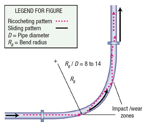
Figure. Flow in a standard, long-radius bend is illustrated here, with typical flow patterns, wear points and reacceleration zone shown
Pressure drop related to bend
As particle impacts occur, particularly against bends, there will be a significant reduction in particle velocity. These particles will then have to be re-accelerated back to their terminal velocity, which will add significantly to the pressure drop — and hence, energy loss — for the conveying system. This is particularly true after short-radius bends.
The pressure drop in a bend depends on the ratio of bend radius to pipe diameter, the gas velocity, Ug, and the internal roughness, k, of the pipe. When a two-phase, gas-solid suspension undergoes a directional change in a pipeline, the bend naturally acts as a segregator of the two phases. Centrifugal forces act on the particles, concentrating them near the outer wall of the bend. Friction coefficients within the bend will be different than those in the adjacent straight sections.
Abrasion of pipe wall
If the material to be conveyed is potentially abrasive, significant wear of the pipeline, especially at the bends, is likely to occur. With a new bend, the particles tend to travel straight on from the preceding straight pipeline until they impact against the bend wall. After impact, they tend to be swept around the outside surface of the bend. They are then gradually entrained in the air in the following straight length of pipeline.
Attrition of particles
If the material being conveyed is potentially friable, damage to the material being conveyed may occur, and it is possible that these changes to the material could affect the conveying performance of the material itself.
Particle breakage. Particle breakdown occurs by three main mechanisms. The first is to shatter or degrade when the bulk solid is subject to impact or compressive loading. The second is for fines and small pieces to be worn away by attrition when bulk solids either rub against each other or against some surface, such as a pipeline wall or bend. The third is for the materials, such as nylons and polymers, to form “angel hairs” when conveyed, as a result of micro-melting, which occurs to due to the frictional heat of particles sliding against pipeline walls.
Operating problems. Particle degradation can cause problems in a number of areas because of changes in particle shape and particle-size distribution that can result. Plant operating difficulties are often experienced because of the fines produced, and problems in handling operations can also result after the material has been conveyed. Apart from the obvious problems of quality control with friable materials, changes in particle shape can also lead to subsequent process difficulties with certain materials. The appearance of the material may also change, making it out of specification.
Filtration problems. In pneumatic conveying systems, plant-operating difficulties can result if degradation causes a large percentage of fines to be produced, particularly if the filtration equipment is not capable of handling the fines satisfactorily. Filter cloths and screens will rapidly block if they have to cope with unexpectedly high flowrates of fine powder. The net result is that there is usually an increase in pressure drop across the filter, and this could be a significant proportion of the total pressure available in a low-pressure system.
Flow problems. In many systems, there is a need to store the conveyed material in a hopper or silo. Flow functions can be determined for bulk particulate materials, from which hopper wall angles and opening sizes can be evaluated, to ensure that the material flows reliably at the rate required. A change in particle-size distribution of a material, as a result of conveying operations, however, can result in a significant change in flow properties. Thus, a hopper designed for a material in the “as-received” condition may be totally unsuitable for the material after it has been conveyed. As a result, it may be necessary to fit an expensive flow aid to the hopper to solve the problem.
Editor’s note: This “Facts at your Fingertips” column is based on infomration from the following articles: Dhodapkar, S., Solt, P. and Klinzing, G., Understanding Pipe Bends in Pneumatic Conveying Systems, Chem. Eng., April 2009, pp. 53–60; and Mills, D., Particle Impact Problems in Pneumatic Conveying, Chem. Eng., March 2017, pp. 69–76.