Several carbon capture and sequestration (CCS) processes hold much promise, and there are challenges yet to be met
A number of post-combustion carbon capture technologies have the capability to reduce the amount of carbon dioxide emitted to the atmosphere from fossil-fuel-fired industrial and utility-power plants. Further interest has been placed in this technology in light of growing concerns about climate change. This article investigates a few of the more promising post-combustion carbon capture processes, including amine-based absorption, ammonia-based absorption, solid sorbent adsorption, membrane filtration and algae. This article also considers some of the challenges associated with compression, transportation and storage of carbon dioxide.
Carbon dioxide in the atmosphere is a greenhouse gas that most scientists consider to be largely responsible for climate change. Among the most significant sources of atmospheric CO2 is fossil-fuel-fired power generation. For many years, technologies for carbon capture and sequestration (CCS) have been under investigation and development as a means of mitigating CO2 emissions while still allowing industries to burn fossil fuels. Currently, three of the most promising techniques for CCS are being developed: post-combustion capture, pre-combustion capture, and oxy-combustion capture. Of these three, post-combustion CCS with amines and with chilled ammonia have had the most relative success and are discussed further in this article.
Current CCS regulations
Governmental support and regulations are needed to provide the incentive for CCS to become widely used in the chemical process industries (CPI) as well as the utility industries. Except for the case in which CO2 is used for enhanced oil recovery (EOR) to increase the capacity of oil wells, CCS currently is not considered financially viable. For the power industry, the main reason is that CCS systems impose an energy penalty of up to 40% of the overall output of plants. When EOR is not feasible, it is not likely that the power industry will provide the investment to install capture systems without regulations or legislation that require carbon emissions reductions.
On June 25, 2013, U.S. President Barack Obama outlined a new national climate action plan that includes focusing on the use of cleaner energy and reducing carbon pollution. The President specifically called for the U.S. Environmental Protection Agency (EPA; Washington, D.C.; www.epa.gov) to complete new limitations on carbon emissions from both new and existing power plants. Following that, in September 2013, the EPA proposed a cap for CO2 emissions for all new coal-fired power plants. This proposal would limit carbon emissions to 500 kilograms per megawatt hour (kg/MWh), which is about half of what average coal plants currently emit. The fundamental effect of this proposed rule would be that no new coal-fired power plants would be built, unless they had the capability for CCS. Furthermore, the November 2013 United Nations Framework Convention on Climate Change (UNFCCC) laid the foundation for a post-Kyoto Protocol agreement to be made in 2015. The 1997 Kyoto Protocol set international carbon-emission-reduction goals and includes two commitment periods. The first period sets a goal that the involved countries will reduce their carbon emissions to 5% below those of 1990. The second commitment period increases that margin to 18% below 1990 emission levels. After the second commitment period ends in 2020, the 2015 agreement will come into place. Reports on the UNFCCC meeting state that the new rule will focus on mitigation, adaptation, finance, technology readiness and transparency of action as it relates to CO2 emissions.
On September 20, 2013, the EPA issued draft carbon-pollution standards for new power plants under Clean Air Act Section 111(b) New Source Provisions. The draft was published in the Federal Register on January 8, 2014. On May 9, 2014 the comment period closed with over 2 million comments. EPA is still reviewing comments on the draft and intends to issue a final regulation in the summer of 2015.
On October 28, 2014, the EPA issued draft carbon-pollution standards for existing power plants. The draft was published in the Federal Register on November 4, 2014. After receiving over 2 million comments on the draft regulation, on January 15, 2015, the EPA announced that it would review and restructure the carbon pollution plan for existing power plants including revising the state targets for carbon pollution reduction. A new revised draft is expected in the summer of 2015.
Absorption-based technologies
Amine-based. The CPI have had the most success with developing CCS technologies using amine-based solvents, such as monoethanolamine (MEA), diethylamine (DEA), methyl diethanoloamine (MDEA), piperazine (PIPA) and 2-amino-2-methylpropanol (AMP). Such chemical solvents have desirable properties in that they often react strongly and quickly with CO2, yet they also release the CO2 while regenerating the solvent. Amine-based solvents are able to remove large amounts of CO2 from fluegas at low pressures.
The basis behind amine-based carbon capture processes is fairly simple (Figure 1). Fluegas from utility and industrial boilers typically contains mostly nitrogen (about 70 vol.%), smaller amounts of water and CO2 (about 20%), and impurities of SO2, NOx, mercury and ash particulate matter. An air-pollution control system must be in place to greatly reduce the presence of these impurities in the fluegas before entering the carbon capture system. The cleaned fluegas then enters a small scrubber vessel to cool the gas and remove more trace sulfur impurities. From the quencher, the fluegas enters the absorber. The absorber uses the amine as a solvent to reduce the CO2 level in the fluegas. This exothermic reaction typically removes about 85–90% of the CO2 from the entering fluegas. The CO2-rich solvent mixture is then sent to a heat exchanger before entering the regenerator. In the regenerator, the solvent is steam-stripped, causing the essentially pure CO2 to come out of solution in an endothermic reaction. The overhead CO2 is then compressed and fed to a pipeline, while the CO2-lean amine solvent is recycled back to the absorber for reuse.
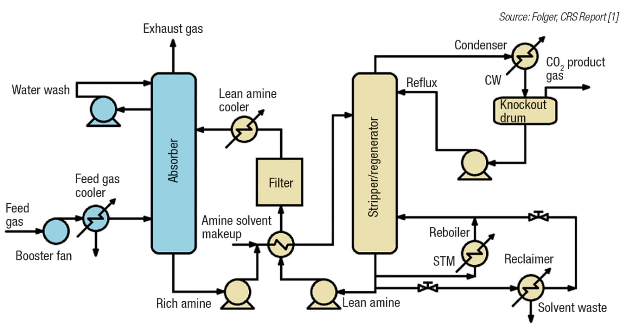
FIGURE 1. An overview of post-combustion, amine-based carbon capture is depicted here
Ammonia-based. Ammonia-based CCS systems show promise for a number of reasons. As compared to amine solvents, ammonia solvents are less-expensive, have lower heats of reaction, and require less energy for regeneration. The use of ammonia could drive overall plant costs down as a result of ammonia’s ability to simultaneously absorb multiple pollutants, such as CO2, SO2, NOx and Hg.
A major challenge associated with ammonia-based systems is that of ammonia slip. Because ammonia is more volatile than amines, it can sometimes be released into the fluegas stream during absorption. If ammonia-based processes are to be economically viable, ammonia slip must be controlled to avoid the need for additional fluegas cleanup.
Alstom (Levallois-Perret Cedex, France; www.alstom.com) developed a process using chilled ammonia that has had success on the pilot-plant level. The process uses ammonium carbonate that has been chilled to about 20°C as the solvent to absorb the CO2 from fluegas, which has also been cooled. The relatively low temperature in the absorber prevents significant ammonia slip from occurring. The overall system flow is similar to the amine-based systems: the CO2-solvent stream is sent to the regenerator where heat is added to cause the CO2 to come out of solution. Then the CO2 stream may be compressed and stored, while the regenerated solvent is recycled to the absorber and used again. While the Alstom process has controlled the amount of ammonia slip by chilling the solvent and fluegas, there are very significant energy costs associated with this chilling. Therefore, ammonia-based processes must be optimized to minimize ammonia slip in the most efficient way possible. Figure 2 shows an outline of the Alstom chilled-ammonia process.
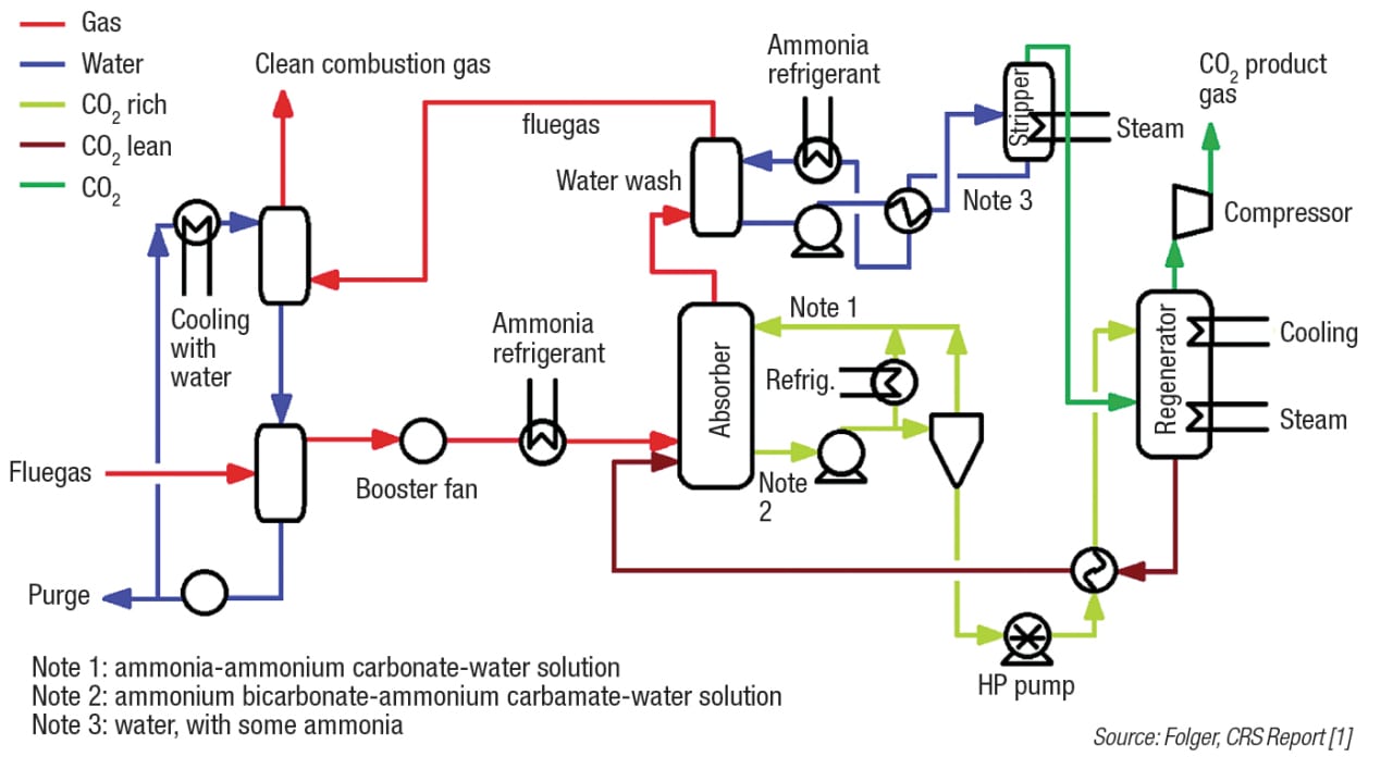
FIGURE 2. The chilled ammonia process has had success on the pilot-plant scale
Adsorption-based technologies
Solid sorbents work by adsorbing the CO2 onto their surfaces (Figure 3). The sorbent is regenerated by changing the temperature or pressure, which causes the CO2 to be released. Solid sorbents hold economic promise over amine-based CCS systems, because less energy is required in the regeneration step. There is no need for steam, and solid sorbents typically have lower energy requirements for sensible heating of regeneration gas than liquid water-based solvents. This means that less sensible heat is required to regenerate the sorbent.
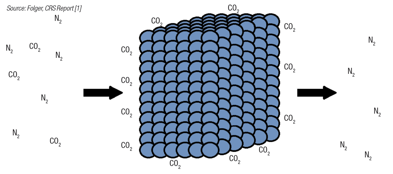
FIGURE 3. Solid sorbents for carbon capture work by adsorbing carbon dioxide onto their surfaces
Adsorption can be a physical or chemical process. Physical adsorption involves materials such as activated carbon, zeolites and metal organic frameworks (MOFs). Activated carbon is known to have a large inter-particulate surface area, thus increasing its CO2 loading capacity. MOFs and zeolites are crystalline sorbents that capture CO2 in their void spaces. Concerns about solids that adsorb physically include: selectivity in carbon capture, CO2 carrying capacity, and physical degradation. Chemical adsorption is similar to the liquid absorption carbon-capture processes. The sorbent can be certain carbonates or amines supported on the surface of other materials, such as activated carbon. Amine sorbents supported on activated carbon have been shown in bench-scale tests to have high CO2 carrying capacities and lower regeneration-energy requirements, since these systems lack water. However, care must be taken to prevent fouling and degradation over time.
Solid sorbents have their own associated challenges, which are different than those found with liquid solvents. As noted, care must be taken that the solid does not deteriorate over time. Solids are also more difficult to handle than liquids, which typically only require pumps. One key engineering challenge is designing a long-lasting sorbent that has a high surface area available for CO2 capture, called carrying capacity. Engineers must also optimize the process to find the best method of handling solids, how to reduce regeneration-energy requirements further, the minimum possible pressure drop, and how to increase reaction rates.
Membrane-based technologies
Membranes are porous materials that filter CO2 from fluegas streams. Gas streams are either pushed or pulled through membranes by a pressure differential. Pressure can be applied to one side of the membrane to push the gas through, or a vacuum can be created on the other side of the membrane to pull the gas through.
Membrane quality is determined by selectivity and permeability. Selectivity refers to a membrane’s ability to filter one component (such as CO2) rather than a different one (for example, N2). Permeability denotes how much of a substance may pass through the membrane for a certain pressure difference. Permeability directly relates to the required membrane surface area needed for adequate CO2 separation.
Research has been done on the laboratory and bench scale to improve membrane selectivity. In one line of research, an amine solvent contacts one side of the membrane to selectively absorb any CO2 from the inlet gas stream that may have accidentally passed through the membrane. Another concept uses enzymes to mimic nature. A liquid membrane system uses carbonic anhydrase, the enzyme that transports CO2 in mammal respiratory systems, to catalyze the transport of CO2 through the membrane. However, membrane CCS systems encounter issues with fouling and scaleup for industrial settings.
Algae-based technologies
Because algae metabolize CO2 to grow, algae ponds have been considered as a CCS method. In addition, waste heat from industrial plants could be used to warm the ponds in winter. Algae grow quickly and can be used for biofuels. The need for pond water is not of significant concern because many algae strains prefer salt water, meaning algae ponds will have no effect on potable fresh water demand.
There are, however, many challenges to overcome when considering algae for CCS. Algae do not take in CO2 very quickly, thus mandating the need for huge, city-sized ponds to process a typical industrial plant’s CO2 output. In addition, the algal biofuel will eventually be burned, releasing its CO2 into the atmosphere. Such an action reduces, but does not eliminate the carbon footprint associated with power production.
Compression, transportation and sequestration
Once the CO2 has been captured, it must be compressed, transported, and either used or stored. The compression and transportation steps are mature technologies. Captured CO2 is often compressed to about 140 bars so that it becomes a supercritical fluid and behaves like a liquid, making it possible to transport CO2 via a centrifugal pump through a pipeline. The critical point of CO2 is reached at 31°C and 74 bars. Therefore, if the temperature and pressure are maintained at about 38°C and 100 bars respectively, the CO2 will still behave somewhat like a liquid and can be pumped to 140 bars for final disposition.
For the transportation of supercritical CO2 in a pipeline, booster pumping stations can be placed along the pipeline to maintain sufficient terminal point pressure if needed. The transport of CO2 through pipelines is a well-understood and safe practice. Carbon dioxide pipelines typically have very few leaks and have not caused any recorded injuries or fatalities. Carbon dioxide may also be transported by ship, but this is only done in small quantities.
Storage and use. It is the final step of CCS, the sequestration or storage of CO2, that has resulted in the greatest controversy. Much of the captured CO2 will be injected underground and stored with minimal leakage. Public opinion as of late has pushed for the practical use, rather than simple storage of the CO2. For industrial boilers in CPI facilities, carbon capture can sometimes be used for the production of chemicals such as urea, methanol, formic acid, cyclic carbonates and polycarbonates. Carbon dioxide can also be used in the production of food and soft drinks. However, this consumption provides only temporary storage for CO2 because much of it is immediately released into the atmosphere upon use. More permanent uses for CO2 include the production of plastics, fertilizers, ceramics and new types of cement. Integration of CO2 use in these areas is likely to take time, so other storage options must be considered.
It is expected that most captured CO2 will be injected and stored underground. The ability to do this depends on the presence of appropriate geological formations that can hold the CO2. Characteristics of an appropriate formation include sufficient volumetric capacity to hold the CO2, the ability to prevent this CO2 from reaching the atmosphere or potable groundwater sources, and the ability to accept CO2 injection at rates comparable to those of oil-and-gas extraction in industry. Some formations that can have the ability to accept CO2 injection include sedimentary rock, oil and gas fields, saline aquifers and coal seams. Underground injection is a safe practice, provided that the injection site is carefully selected, the injection operations are properly performed, and the CO2 is monitored during and after injection.
Looking ahead
Carbon capture and sequestration are both likely to increase in importance in the near future. International focus on reducing carbon emissions has brought forth new regulations that enforce and promote CCS technologies. The most advanced CCS methods include post-combustion amine-based and ammonia-based absorption of CO2, but other methods are being researched and developed as well. While the compression and transport of CO2 is a mature technology, the storage and use of CO2 have been a source of controversy. More research needs to be done in order to find additional ways to permanently use CO2, and to ensure the safety of underground injection. ■
Edited by Dorothy Lozowski
Acknowledgments
The authors thank Mitchell Krasnopoler of Kiewit Power Engineers for providing valuable comments for this article.
References
1. Folger, P., Carbon Capture: A Technology Assessment, Congressional Research Service Reports, Retrieved from Digital Commons@University of Nebraska-Lincoln: digitalcommons.unl.edu/crsdocs/19/, November 5, 2013.
2. Mills, R. M., “Capturing Carbon: The New Weapon in the War Against Climate Change”, New York, Columbia University Press, 2010.
3. Rameshni, M., Carbon Capture Overview, Worley Parsons, Retrieved January 7, 2014, from www.worleyparsons.com/CSG/hydrocarbons/specialtycapabilities/documents/carbon%20capture%20overview%20(3).pdf, 2010.
For more on CCS, see CO2 Gets Grounded, Chem. Eng., April 2014 at www.chemengonline.com.
Authors
 Julie Horn is a process engineer for Kiewit Power Engineers Co. (9401 Renner Blvd., Lenexa, KS 666219; Email:julia.horn@kiewit.com). She recently graduated with honors from the University of Nebraska-Lincoln, where she obtained a B.S.Ch.E. Horn performed research as part of an REU (research experience for undergraduates) at Iowa State University and has also interned at Aventine Renewable Energy.
 Raymond Eric Zbacnik is a senior process engineer for Kiewit Power Engineers (Email: raymond.zbacnik@kiewit.com). Zbacnik has about 40 years of chemical process engineering experience, which includes 20 years of air-quality control systems (AQCS) experience in the power industry. He worked at Babcock & Wilcox, at HDR: Cummins & Barnard and at Foster Wheeler. Zbacnik has a B.S.Ch.E. from Purdue University, and an M.E.Ch.E. from Manhattan College. He is a member of the AIChE, IChemE, ACS and AWMA.