A better understanding of what pressure instruments do and how they work can help improve measurement performance, especially in troublesome applications
Effective use of process instrumentation is critical in any chemical manufacturing environment. These instruments are strategically located throughout various units and measure all types of process variables, and are the operators’ eyes and ears to the world inside the vessels and pipes. Ensuring good performance requires careful selection, proper installation and ongoing maintenance.
These concepts apply to all types of instrumentation, including flow, level, temperature, pressure and other measurement categories. We will concentrate on pressure in this article because these instruments are at the heart of many techniques for measuring not only pressure, but also flow and level. Getting reliable and accurate pressure measurements can be a challenge, often due to installation difficulties and other issues. But modern industrial pressure instruments address many of these issues and are exceptionally stable, accurate and durable.
Spending a few moments thinking about how pressure is measured can help a user sort through the mechanics of an application and ensure that it performs exactly as desired. The simplest pressure instrument is a manometer, a U-shaped tube partially filled with a liquid of known density such as water. If both ends are open to the atmosphere, the two sides of the liquid slug will be of equal height. If pressure is applied on one end but not the other, the liquid will go down on the side where pressure is applied and up on the other. The difference in height can be measured, and this unit of measure is commonly used to determine pressure.
If unequal pressure above atmospheric pressure is exerted on both ends, the greater pressure will overcome the lesser. This is differential pressure (DP), since there are two dynamic sources of pressure on opposite sides of the slug of liquid.
Pressure measurements can be thought of as differential measurements referenced to different points. These reference points can be tied to atmospheric pressure in the case of a gage transmitter, vacuum in the case of an absolute pressure transmitter, or other process points in terms of a DP reading. Most applications use gage or DP, although for some applications, absolute pressure readings are necessary.
What is a pressure instrument?
In the manometer tube, the liquid indicates the pressure visually. With a pressure instrument, a diaphragm essentially replaces the slug of liquid in the manometer tube, and there is a mechanism capable of measuring the amount of displacement. The diaphragm and its measuring mechanism together make up the sensor, which creates an electrical signal in proportion to the pressure.
Consider what a pressure instrument does and its construction (Figure 1). Measuring process pressure requires a liquid, gas, slurry or some other media to apply pressure against an isolating diaphragm capable of moving the sensor to create a signal. In the example in Figure 1, when pressure is applied, the isolator applies pressure to the fill fluid, often oil, which in turn will move the sensor. The movement of the sensor can then be electronically processed by the transmitter.
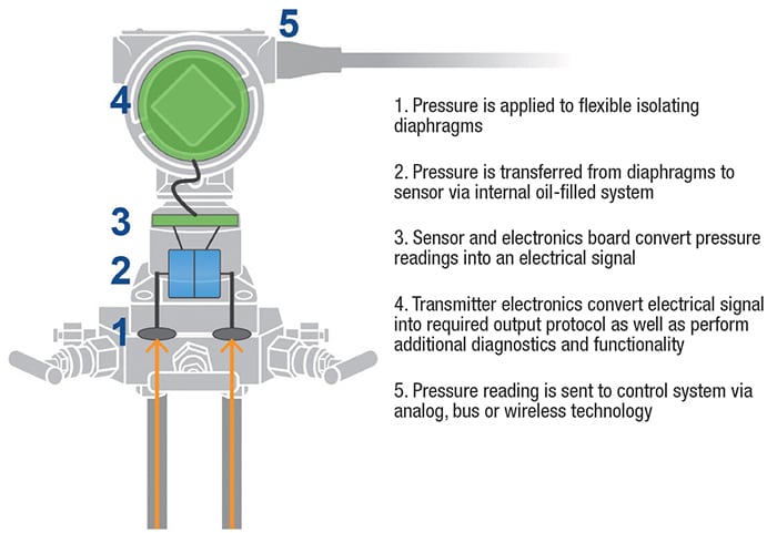
Figure 1. This is a representative illustration of the working internals of a differential pressure instrument
This measurement mechanism can be capacitive, where the capacitance between the moving diaphragm and stationary surface can be measured, or mechanical, where a strain on the sensor causes flexing. The key function of the sensor is to convert small mechanical movements into electrical signals. These signals are then often converted mathematically in the transmitter to produce a pressure reading. The final output of an instrument uses a standardized signal protocol, which can be integrated into an automation system.
With simple pressure-measuring devices, such as manometers or Bourdon-tube gages, the process fluid is often allowed to flow into the instrument and come into direct contact with the sensor, which can work well for non-corrosive types of applications, such as water. In these simple examples, the sensor is often referenced to the atmosphere, thus displaying a gage reading.
If, on the non-process side of the sensor, the air has been evacuated to create a vacuum, this yields an absolute pressure measurement. Another way to create an absolute pressure reading is to correct a conventional gage value by deducting atmospheric pressure. For a DP instrument, the backside of the diaphragm is connected to a second process pressure inlet.
For most applications, the sensor’s raw signal is not very useful, so the pressure instrument processes the signal and converts it to a standardized format or engineering unit, such as bars, pounds per square inch (psi) or inches of water (in. H 2 O). This processing is necessary because pressure sensors are non-linear and affected by temperature.
Therefore, the transmitter also includes at least one temperature sensor to compensate the pressure readings for temperature conditions. The transmitter will often make this additional measurement available digitally. The processor in the transmitter will also convert this information to a digital protocol so the transmitter can report the pressure to an automation system. For instance, this can be done with a 4–20-mA output with the HART protocol.
For small, inexpensive pressure devices, often referred to as transducers, the sensor and transmitter may all be built into a single compact housing with a threaded inlet and wire pigtails for the connection. For typical chemical-process installations, pressure instruments are often designed with DP configurations with the sensor housed in a manifold. Connections can be made using impulse lines from the process penetration. If used in a gage pressure application, the second connection is simply left open to atmosphere. Elaborate manifold configurations (Figure 2) can be outfitted with valves to close off and bleed the impulse line, simplifying maintenance.
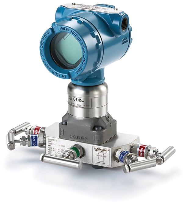
Figure 2. Manifolds have a wide variety of configurations to assist with routine maintenance activities
In some situations, where the process is especially hot or fluid characteristics are dangerous, containment is critical and impulse lines are undesirable. A remote seal can be installed at the process penetration, and its connection back to the instrument can be filled with oils, inert liquids or other fluids, which move the sensitive electronics away from the hot conditions via remote seal lines (Figure 3). These seal lines also act as a temperature barrier. The pressure information is passed hydraulically via the fill fluid to the sensor, while containing the process fluid in the piping or vessel.

Figure 3. This remote seal configuration can be mounted in direct contact with the process fluid, and the pressure transmitted via an inert fluid to the pressure sensor
This same methodology can be used for installations in hazardous environments, which often also use an isolator to separate the transmitter electronics from the process connection. The remote seals add one or more additional layers of process protection, especially important in highly corrosive installations. If the diaphragm fails and allows process fluid to escape, some less robust instruments may provide a path for process fluid to flow through the housing and out the electrical conduit, allowing it to reach the connection point or some point in between. More advanced transmitters provide isolation with dual compartment housings able to isolate the sensing side from the loop connection side.
The transmitter
The transmitter is integrated into the overall pressure instrument and contains a significant amount of electronics to perform a variety of functions to make it widely usable for many different applications. Understanding what these devices do can help clarify equipment selection for specific applications.
As previously mentioned, the electronics in the transmitter are responsible for taking the raw sensor information and turning it into pressure information. Depending on the sensor type, this correction addresses things like sensor non-linearity and temperature correction, as well as providing the other features found in the transmitter.
In many cases, pressure transmitters require a temperature sensor near the pressure measurement point for correction of the pressure reading. In some cases the electronics can also accommodate a process temperature sensor, which is very helpful for multi-variable DP flowmeters where process temperature correction is required in the flow calculations. These temperature and pressure measurements are often available as secondary variables and can be conveyed digitally to an automation system.
Additionally, the transmitter must convert the pressure information into an output signal, which may be an analog current or voltage value, or a digital signal. For analog, 4–20 mA is by far the most common transmitter interface, often including digital HART data superimposed on the analog signal.
Digital signals are usually Foundation Fieldbus, Profibus PA, WirelessHART or other industrial protocols. Few field instruments these days are simple analog, with most including both analog and digital capabilities. With the digital capabilities, these instruments can transmit data in addition to the process variable including configuration, secondary variables and critical diagnostic information.
With the flexibility added by configuration features, pressure transmitters enable users to set many parameters often including the following:
Ranging. A pressure sensor has a fixed useful range. With that said, many transmitters offer range-down capabilities. This enables a transmitter with a wider sensor range to be ranged down to meet an application with lower pressure requirements. This range-down is limited by accuracy, so care must be taken to ensure sufficient measurement sensitivity even at very low pressure changes. If a sensor has a useful working range of 0–250 in. H2O, using it to measure 0–25 in. H2O is a reasonable range-down of 10:1. Even though the range can be set for the lower values, this will not affect the mechanical characteristics of the sensor and some accuracy will be lost. Investing in devices with a wider range-down capability can optimize pressure instrument inventories.
Diagnostics. Some pressure instruments are aware of their surroundings and what is happening with the process. They get used to the normal operating patterns and can warn operators when conditions change. The transmitter also typically monitors itself, looking for changes in its own internal components. If given the means to communicate, as with a digital instrument, it can report changes and developing problems to the automation system and operators, so action can be taken before failure.
Temperature. As mentioned, sensor technologies are often affected by temperature. As a result, an instrument will have a useful working temperature range to protect sensitive electronics, as well as suitable process temperatures for which correction is possible, just as it has a working pressure range. Some applications can be too hot or cold for the sensor and electronics, an area which will be covered in more detail later in this article.
Protocol. Pressure instruments need mechanisms to convey all their information, which digital communication uses to get more information from the field to the automation system. For example, in the case of a fieldbus protocol, digital information is provided with regular updates. With greater sophistication comes greater complexity as adding capabilities requires more settings and configuration. The protocol selection is often hardware based. A Foundation Fieldbus instrument cannot be changed to HART via a menu. However, external devices can add wireless connectivity, sending and receiving data via WirelessHART, but this is defined by the hardware components rather than by setting a configuration.
Hazardous location requirements. Most modern field instruments are designed to operate in many environments, including hazardous areas such as Class 1/Div. 1 or Zone 0, provided they are installed and maintained properly. But, it is still very important to determine what ratings are required for each application.
Function influences application
Once the working fundamentals of pressure instruments are clear, it is easier to see where one might encounter difficulties. Incorrect specifications can happen, such as choosing operational characteristics unsuited to the application. For example, choosing a 0–10-bars instrument for an application where the normal working pressure is 10 bars is not correct, because the working pressure is too close to the instrument’s maximum measurement range. Instruments installed incorrectly can interfere with normal operation. Manufacturers provide extensive information as to installation practices, and it is important to follow these for reliable performance.
Maintenance problems can be the result of misspecification. Instruments made over the last 10 years or more are calibrated at the factory using highly sophisticated and accurate equipment and are exceptionally stable. Maintenance workers who may believe electronic sensors need to be tweaked out of the box for accuracy, like a mechanical gage, will often take the instrument out of specification if they do not have the proper training and calibration equipment. After some number of years, most manufacturers do recommend recalibration. The traditional concepts of “sensor drift” applied to mechanical instruments have evolved, and recommended best practices are to calibrate when required.
Process pressure spikes can cause damage to pressure equipment. These can come from improper valve movements, process upsets and sudden pressure events. Installing instruments with high-pressure ranges capable of withstanding these spikes is one solution, but running a process at the lower end of an instrument’s range may cause sensitivity issues. Selecting quality instrumentation able to handle overpressure conditions can help withstand pressure spikes and deliver good measurement performance.
Impulse lines
One option when measuring pressure is to transmit the process media condition hydraulically. A pipe or tube can be mounted between the sensor and the tap, allowing the sensor to be mounted a considerable distance from the process equipment (Figure 4). This approach works because the pressure is static, so there is no significant pressure loss over the length of the tube. An instrument can be mounted in a location based on easier access, distance from a hot or dangerous process, or proximity to both ends of a differential measurement.
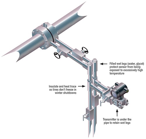
Figure 4. This is a typical DP flowmeter installation with impulse lines, including typical practices to fill wet legs with a fluid able to withstand wide temperature swings
Where gases are involved, usually the process gas fills the impulse lines, which are called dry legs. As long as they stay dry, there are rarely problems, but liquid can find its way into these dead legs through condensation or other sources. Liquid intrusion doesn’t necessarily cause immediate problems, but if the liquid freezes, it can block the line or damage the tubing or sensor due to expansion. Bleeding dry legs routinely, particularly during cold weather, may be necessary.
Where liquids are involved, the process liquid fills the impulse lines, which are called wet legs. Again, if the lines are filled completely with liquid, no problems may develop. However, gas can become trapped in a line, and adding a compressible element to the chain can interfere with accurate pressure transmission. Bleeding wet legs to eliminate gas slugs may be necessary.
Additionally, in either wet- or dry-leg installations, mounting best practices can help eliminate measurement challenges. By mounting a pressure device with a liquid leg below the process connection, gas bubbles that form can work their way out to the process, keeping the wet leg filled. Mounting the pressure transmitter above a gas line can also help liquids flow out of the impulse lines.
Either type of line can become clogged either through sediment or frozen liquid. Bleeding can clear the line, or at least confirm the clog exists.
But having wet legs filled with process fluid has drawbacks. The fluid’s hazardous nature may make it dangerous, its characteristics outside of the process may change, and it may be subject to viscosity changes at different temperatures. Where wet legs have challenges, remote seals can often be used as an alternative to solve some of these problems.
A remote seal can be added at the process tap point(s), with fill fluid added to the line and permanently sealed in the space next to the actual measuring sensor diaphragm. It is important to select the correct fill fluid suitable for the specific application. As is the case with most fluids, characteristics change as a function of temperature. Viscosity increases as temperature decreases, and if it gets too hot, the fill fluid can flash into vapor.
If the fill-fluid line is long, the temperature difference between a hot process and a sensor some distance away in a cold climate could easily be 200ºF or more. Some heat will be transmitted down the line, but even with stainless steel tubing, it dissipates quickly. A good rule of thumb is that a fill fluid can lose 100ºF for every foot, though this can be significantly more depending on installations and ambient conditions. Figure 5 highlights this rapid heat loss in relation to installed distance [ 1]. One end can be hot while the other is cool, causing slow measurement response. Heat tracing is one solution, but it is expensive and maintenance-intensive. Another approach uses an integral enclosure to protect the impulse lines and minimize heat transfer problems (Figure 6).
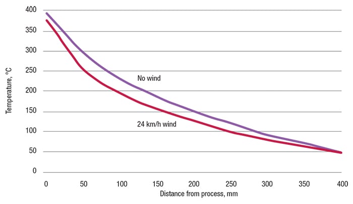
Figure 5. This graph shows process heat dissipation versus distance from transmitter curve (Redrawn from Ref. 1)
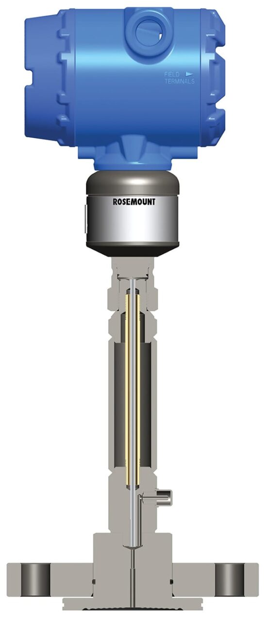
Figure 6. In some hot applications, it is required to add additional separation from the process heat to the transmitter. This shows an example cut-away view where the oil fill lines extend to the sensor and protect the temperature of the transmitter
In tough applications where process temperatures are extreme or ambient temperatures swing significantly throughout the year, dual seals with multiple fill fluids can help. In some instances, electronic remote sensors can eliminate several of the traditional challenges. This approach eliminates the need for a long capillary by connecting the two transmitters electronically, one at each tap point, rather than using a single device and long impulse lines or capillaries. Electronic remote sensors also eliminate heat tracing and associated maintenance challenges. Using systems with closed fill fluids or electronic remote sensors can overcome many challenging combinations of temperatures likely to be encountered in process plants and facilities.
Differential pressure challenges
DP measurements are made in all kinds of process plant areas. Examples include measuring level in tanks, flows through pipes, clogging in strainers, and many more applications. Since DP installations need connections to two process points, and those points could be some distance apart, they may call for the longest impulse lines.
Consider this example: measuring level in a large pressurized tank (Figure 7, left panel). The pressure instrument is mounted near the tank with an impulse line from a spud near the bottom connected to the high side of the DP manifold. The low side is a line running to the top of the tank, say 10-m high, to measure the pressure in the headspace above the liquid. This dry leg comes down the side of the tank and is connected to the low side of the manifold. The two sides may present significantly different temperatures depending on the contents of the tank. But as long as everything works properly, the level measurement will be correct within the accuracy limits of the process connections. However, there is a risk that the dry leg could collect liquid or the wet leg could trap some gas, in either case introducing potential problems.
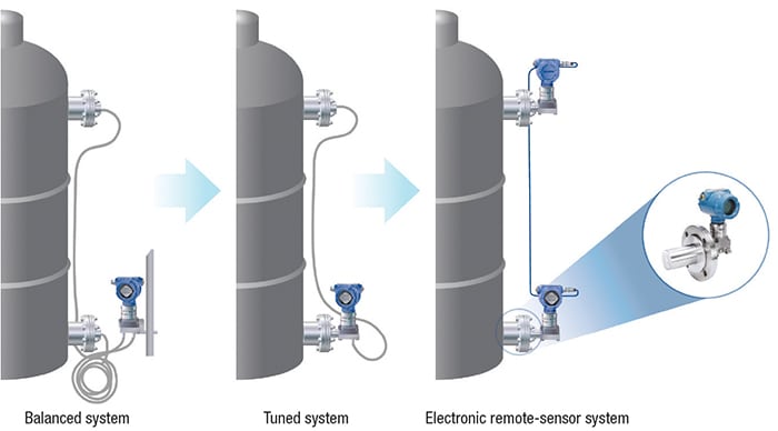
Figure 7. These illustrations show three typical level measuring approaches each providing measurement benefits in different applications
A different approach is to utilize a tuned remote seal on the lower connection (Figure 7, center and right) instead of an impulse line. This avoids any potential for clogging of the wet leg. Of course it is still important to select the correct capillary fill fluid for optimal temperature performance.
A third alternative, if static pressure isn’t too high, is to mount a second pressure instrument on top of the tank instead of using an impulse line (Figure 7, right panel). For optimal performance, an electrical connection between the two instruments provides a means to synchronize the measurements. This configuration removes the capillary piping and significantly reduces temperature effects. This pressure measurement system can be configured as a single instrument, with the DP reading sent to the automation system as the primary variable, and the two static pressure measurements sent to the automation system as secondary variables. This approach eliminates many of the challenges inherent to impulse lines and capillaries (for more on this approach, see Part 2, “Measuring Differential Pressure: Mechanical or Electronic?” ).
Challenges within the CPI
Many chemical manufacturing processes involve a variety of toxic, flammable or corrosive products at a huge range of possible temperatures. While conventional stainless-steel construction is well suited to most chemical environments, special materials may be necessary in particularly difficult situations. High-nickel alloys (for example, various grades of Hastelloy, Inconel and so on) are common, along with zirconium in applications such as urea production.
These special materials are higher cost, so they should be used strategically in appropriate applications where they perform significantly better than traditional materials. Using the right material not only extends the life of the instrument, but reduces the probability of failure with consequent leak points and possible shutdowns.
Applications where special materials are required need careful design to avoid becoming overly expensive and complex. For example, using conventional impulse line configurations requires the use of special tubing and fittings along with the non-standard instrument manifold. If a transmitter can be selected with a remote seal, the special impulse line can be eliminated, and only the single wetted part needs to be made from the special material.
New devices, old environments
Many chemical plants were built decades ago. Compared to current practices, plant designs of those times had sparse instrumentation and automation. Older automation platforms usually support only simple analog field instruments, with no built-in support for digital instruments.
Adding communication from today’s digital instruments can be challenging, but when applied properly and coupled with suitable work practices, it is well worth the effort. Communication from existing HART instruments can be added using three basic approaches:
- Replacing analog input cards with HART input cards. These upgraded I/O cards enable digital communications with field equipment, but must be supported by the automation control system
- In the case where the automation system doesn’t support HART, multiplexers can tap into the existing I/O and extract the HART data, and transmit these data via discrete or 4–20-mA signals
- If the need is to access specific field instruments for strategic information, external wireless adapters can be added. These adapters send digital data to a gateway, with the gateway hard-wired to the automation system. These devices do not interfere with normal operation of the analog loop, but are powered by the loop. They act just as if the device was hooked up to a modem, and provide access to valuable data along with instrument configuration capabilities
Adding new field instruments where cable trays are crowded and automation system I/O panels are filled to the maximum is difficult and expensive. Wireless instruments avoid these infrastructure problems and can be deployed throughout a plant without extra cabling or conduit.
Most wireless instruments are entirely self-contained with internal power supplies capable of operating for many years. They can also be placed in most hazardous environments without the usual concerns related to conventional wiring infrastructure installation and maintenance.
Weather & environmental issues
Chemical plants are not always located in temperate hospitable environments. Those sited with petroleum-production facilities can be very hot or very cold. Temperatures in the Middle East can routinely reach 50ºC with daily swings of 15ºC. The Athabasca oil sands in Canada can go the opposite direction, requiring field instruments to operate at –55ºC and even lower.
This can play havoc with impulse lines by causing blockages due to frozen fill fluids, measurement latency caused by high viscosity of fill fluids at low temperatures, or low-molecular-weight fill fluids being vaporized by heat. Sensitive electronics can also be affected by ambient conditions. Where temperatures are extreme but steady, finding a solution is usually manageable. Bigger problems occur where temperatures fluctuate from very cold to very hot.
With a continuous process, the process temperature stays stable, but batch processes change as they start up and shut down. If appropriate compensation is not included, the same batch process starting at 5:00 a.m. in Saudi Arabia can perform differently when starting at 5:00 p.m. due to significant ambient environment temperature swings. By selecting fill fluids and appropriately rated devices, accommodations can be made to deal with these issues.
In addition, modern instruments monitor the transmitter temperature and therefore know when it is outside of its reliable operating range. These instruments can warn operators via diagnostics of potential problems with the readings so that corrective measures can be taken.
Listening to the diagnostics
A surprise failure of a smart pressure instrument (short of it receiving damage from an external source) should be a rare event. Many failures are not immediate, nor are they difficult for the transmitter’s own diagnostic routines to detect. If a plant is monitoring the rich diagnostic data available from a modern digital pressure instrument, warnings of a growing device problem often become evident well in advance of failure.
Some pressure instruments can monitor for subtle process changes. Sensors can function as a process diagnostic tool by analyzing noise signatures. Since good modern transmitters sample data in excess of 20 times per second, additional process insights can be identified. Over time, normal operation creates a specific noise signature, and signature changes can warn operators of an impending problem. For example, if the amplitude of the process noise falls, it may be due to an impulse line clogging.
Of course, diagnostics depend on automation systems and operators. For plants where field instruments communicate via a fieldbus or with native HART-enabled I/O, this is a simple matter to implement. Older systems using analog I/O will need to use a HART multiplexer or wireless solution to benefit from this enhanced available information.
Flow measurements
DP instruments are at the heart of many flow-measuring techniques, using disruptions in moving process media streams caused by an obstruction, such as an orifice plate (Figure 8). The characteristics of these technologies have been the topic of many articles, but some difficulties are caused when the pressure instrument is not performing optimally due to a mounting or maintenance issue.
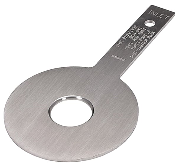
Figure 8. Example of an orifice plate utilized in flow applications
Most flowmeters are designed to minimize the amount of pressure loss they create since this is a waste of energy. Therefore, the pressure instrument has to be very sensitive and precise when measuring what might be a very small differential, even though the line pressure could be very high. Impulse lines should be kept as short as possible since even a small obstruction can affect a low level measurement.
Some newer flowmeter designs eliminate impulse lines entirely, building the flow-disruption device and pressure sensor into one integrated unit (Figure 9). This simplifies installation and maintenance, particularly in situations where special materials are needed.
Situations with high line pressures but a low differential can be difficult, especially when it comes to maintenance. Anyone installing or working on such an installation should be careful not to pressurize only one side of the pressure instrument, as this would subject the sensor to full line pressure. If the sensor can’t withstand this overpressure, damage or even a leak could result.
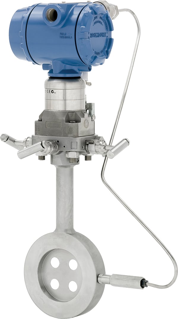
Figure 9. Newer DP-based flowmeters use an integrated design, simplifying the construction and reducing potential maintenance problems
Reference
1. Brown, Stephen R., and Menezes, Mark, Measurement Best Practices for Safety Instrumented Systems, Chem. Eng., September 2006, pp. 66–72.
Author
 Wally Baker is currently a marketing manager for the Worldwide Pressure Product group of Emerson Automation Solutions (8200 Market Blvd., Chanhassen, MN 55317; Phone: 952-949-7242; Fax: 952-949-5068; Email: wally.baker@emerson.com), and is responsible for Rosemount Wireless Pressure Products. He has 15 years experience in industrial process and control. While at Emerson, he has held positions as Global Wireless O&G business development manager, sales and marketing manager for Asia Pacific Wireless & Plantweb, global product marketing manager in the Rosemount Temperature Business Unit, and spent five years in the Rosemount Pressure Engineering & Design team as an electrical and software engineer. Baker holds an E.E. degree from Iowa State University and an M.B.A. from the University of Minnesota.