Dust collection systems are often designed using simple rules of thumb that may not be sufficient for proper operation. Flow analysis can ensure that the systems meet requirements
The presence of dust is one of the many potential causes for explosions and fires at process plants. Dust collection systems can provide a significant level of explosion prevention, and they can also help maintain a safe working environment and reliable equipment operation.
Despite their status as critical components in a plant’s overall safety infrastructure, dust collection system designs are often based on simplified rules of thumb, rather than being rigorously designed like other process units and systems in a plant. Using basic rules of thumb to guide designs can be problematic because designers assume that the rules of thumb will necessarily lead to a properly functional system. Flow analysis of dust control systems finds that this is often not the case. Dust collection systems that are “thrown together” without well-thought-out designs can introduce problems and the system may not work properly. In addition, new pieces of equipment get added to a process over time as production expands, and the dust collection system quickly becomes increasingly complicated. This leads to uncertainty regarding its functionality.
To reduce the risk of dust explosions and ensure that a dust collection system is meeting the requirements of the process, it is imperative to go a step further than rule-of-thumb designs and perform a system-level flow analysis. Accurate system-level flow analysis of dust collection systems is critical for explosion prevention in process plant operations. This article discusses considerations for flow analyses of dust collection systems, including the use of flow analysis to aid design for normal operation, as well as various operating scenarios when different components and flow paths are online at different times, and whenever additional branch paths are added into an existing system.
Potential dust hazards
There are five critical conditions that when met, can lead to a disastrous explosion event, such as the one that occurred at the Imperial Sugar Refinery in Georgia in February 2008 that killed 14 people and injured 38 others [1]. In addition to the three components needed for all combustion — fuel (in this case a combustible dust), oxidant and ignition source — dust explosions also require the dust to be dispersed in the atmosphere and confined.
Dust is just one of the many fuel sources that can cause explosions and it is difficult to know which types of dust can explode, and under what conditions, and which ones will not. Therefore, whenever dust is present, a dust hazards analysis (DHA) is performed to determine the dust characteristics and assess the potential for explosion. With information from the DHA, plant designers and operators can determine methods of prevention and mitigation of dust explosions.
Design considerations
The primary function of a dust collection system is to provide points of entry into the ducting network where dust can be collected and then transported into a primary dust collector. The dust collection system is basically a large vacuum, so high velocities and flows are needed to transport the dust through the ducting network.
When dust collection systems are not working as they should, dust may start to accumulate within the ducting. If moisture is present, then dust can begin to stick to walls and fittings. This is just one of many examples of how a dust collection system may fail — continued analysis can help avoid this. The following are some of the main areas that must be considered for designing a dust collection system.
Flow velocities. If velocities are too low, then dust may settle and increase system pressure drop, which leads to higher energy costs, because blowers must overcome higher levels of resistance. Even worse is potentially plugging up the ducting. Excessively high velocities can also be an issue. High velocities can cause the dust to erode ducting and other network components. Also, dust flowing at too high a velocity may hit features like sharp turn elbows or branch line connections, which can potentially cause an accumulation of dust at those points. Another issue is that if dust is moist or sticky, it might smear along the wall, also leading to potential ducting erosion and accumulation.
The velocity in a certain duct branch line may be adequate for proper transport. However, when it ties into another duct line, the combined flows may lead to excessive velocities. Combined flows and associated velocities are just as important to pay attention to as individual branch line velocities. Basic, rudimentary designs based on simplified rules-of-thumb likely will not allow designs to arrive at the correct flow velocities for a dust collection system.
Compressible flow. A major aspect of a dust collection system that is often overlooked is the fact that it is a compressible flow system. Most often, dust collection systems are assumed to be incompressible, and this leads to uncertainties when real gas effects are not dealt with correctly. Various rules of thumb exist that some will apply for when to treat a compressible system as incompressible and often these assumptions and rules of thumb fall short.
Due to the nature of compressibility, the flow inside the system will tend to accelerate. This can lead to excessive velocities and pressure drops and would not be determined and dealt with properly if constant velocities under incompressible flow assumptions are employed. Also, temperature change and heat transfer play an important role in compressible flow of gas piping and ducting systems. Compression heating through blowers will increase temperatures and it is important to monitor that the resulting temperatures do not reach unsafe levels.
Dust buildup. It is critical to ensure that dust does not collect and build-up within the ducting system. If it does, this can cause a dust collection system to become a part of the problem instead of part of the solution. Accumulated dust inside the ducting network is an explosion or fire hazard. Another major concern is that the accumulation can cause an explosion or fire that may have been started and caused by some other means in the plant to quickly propagate an explosion or fire through the ducting system itself.
System-level flow analysis
Overall, ensuring flow velocities that are not too low or too high, and obtaining the proper system flow capacity is easily achieved through system-level flow analysis. Once the design has been proven functional through the flow analysis, other operating scenarios must be considered. This includes simulating when various branch lines are online or not, as well as the effect on system performance if excessive dust buildup is present, or when the dust collector and filters need to be changed, and when branch lines are added and removed. Dust collection systems often evolve significantly over time and a quality flow analysis can save time in rebalancing the system.
Before designing a dust collection system, one needs to know the location of the equipment producing dust to identify the location of the dust collection unit. Floor-to-joist measurements need to be determined so elevation data can be handled properly. Any obstructions interfering with the ducting (such as walls or other pieces of equipment) or direction changes need to be known.
Next, the ductwork layout can be established. The duct sizes are then determined during the design and calculation process based upon the rules of thumb and associated flow and velocity requirements. Figure 1 is an example of a very simple dust collection system for a manufacturing facility. The system in Figure 1 is what the dust collection system might look like after the layout and duct sizing has been determined.
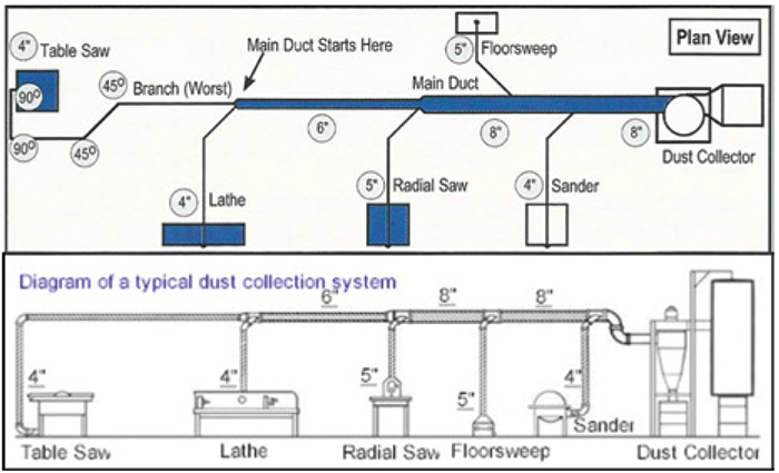
FIGURE 1. The diagram shows an example of a simple dust collection system with multiple pieces of equipment after layout and duct sizing has been determined
The basics of dust-collection system design start with the duct velocity requirements for transporting dust of different types. Velocities typically range between 3,500 and 4,500 ft3/min. Based upon the specific velocities needed for the type of dust being dealt with, the ductwork can be sized for the branch lines from the equipment to the main duct headers depending on the flow requirements of the equipment. Figure 3 provides some examples of various velocity requirements for different kinds of dust and the flow requirements for different duct sizes at specific velocities.
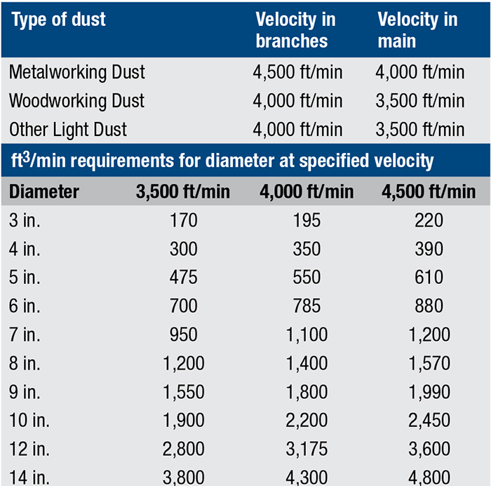
FIGURE 2. Example dust types have different velocity requirements and equipment flow requirements for various duct sizes at specified velocities
Dust collection example
This manufacturing facility has a combination of “primary” and “secondary” pieces of equipment. Primary equipment usually includes major equipment units that are operating at the same time. This would typically start as a base-case scenario in a flow model to simulate the maximum flow requirements. In this system, the radial saw machine has a higher flow requirement than the table saw and lathe. The floor sweep and sander are secondary components that are considered to not be operating while the other three are during the main ducting header sizing process.
The design basis with only three “primary” pieces of equipment operating is another reason why flow analysis is critical. Consider the possibility that all five pieces of equipment are on at the same time? Will the ducting header still be the right size to handle the additional flow capacity to the dust collector? How much more pressure drop will there be with the higher velocities? Will main ducting velocities be too high that may cause problems discussed earlier?
These are all important questions that can only be answered with a detailed analysis. And this is only one other operating scenario where all pieces of equipment are operating. These same types of questions would apply for other cases that can include but are not limited to the addition of more branch lines for new pieces of equipment, the impact from dust buildup inside the ducting, and many other scenarios.
System resistance is usually also determined under rudimentary rules of thumb, which includes determining pressure drop based upon a certain length of ducting at different ducting sizes and velocities. Minor losses can either be dealt with by determining the losses in terms of inches of water, for example, or to convert the losses to equivalent lengths of piping. Once the design is finished, parts and equipment can be ordered and installed.
However, the question is: will this system work as designed? Unless users conduct a proper flow analysis, the assumption would be that it does work, and that can be potentially dangerous, if unchecked.
Software requirements
A flow model of the simple system in Figure 1 can be constructed relatively easily with flow-analysis software. Make sure it is a flow-analysis software that properly handles the complex nature of compressible flow. Basic required input for the model would include duct sizes, lengths, elevation data, loss factors for minor losses and the flow requirements for the blower or fan. The system flow model might look something like that in Figure 3.
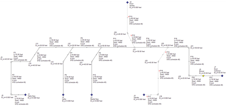
FIGURE 3. The diagram shows a system flow analysis model of the dust collection system example from Figure 1. Input is displayed for duct sizes, lengths, schedules, elevations and so on
A quality flow-analysis software tool should allow users to easily display system model input information directly on top of the graphical model itself. This allows engineers to ensure the model is correct to achieve accurate results. It also helps others to be able to easily follow along with what is happening in the system if they are not intimately familiar with the design.
Another helpful feature that a quality flow-analysis software should have is the ability to alert the user when a design limitation is exceeded. The system model in Figure 3 has design requirements for minimum velocities and minimum flowrates in the various flow lines. Maximum velocities can be set up as well, to alert the user of possible erosion velocities. But for the sake of simplicity, this model only considers minimum velocities and flowrates. Erosion may take a long time and depends on the material and how long the system operates at erosional velocities. This may not always be as much of a concern in cases where velocities and flowrates are too low, where dust can begin to accumulate.
Identifying issues
After running a flow analysis for the scenario shown in the example in Figure 1 with only the table saw, lathe and radial saw operating, it was observed that the minimum required velocities and flowrates were not met in several areas. The velocities and flowrates were significantly lower than what they needed to be in the branch line with the table saw and the main ducting header between when the lathe branch line ties into the main header and where the radial saw branch line ties in. Therefore, we immediately can determine that the design that was established based upon rudimentary rules-of-thumb does not get the job done.
If this design was not checked with a system flow analysis, then dust collection problems may have started to occur and lead to a potentially terrible explosion incident that we all want to avoid. This analysis was only for one scenario. Other scenarios, such as when all pieces of equipment are operating, resulted in all the primary pieces of equipment and their branch lines not being able to meet the required velocities, as well as the main header line up to the point where the sander ties in. Again, this is another clear example of how the rules of thumb governing the dust-collection-system design will fail to produce a properly operating system.
Figure 4 provides an example of how systems quickly evolve and expand as new pieces of equipment and branch lines are added into existing systems. Expansions of dust collection systems are rarely ever analyzed, and similar to the way the initial design (based upon simple rules of thumb) does not work, the flow analysis model shows that the dust collection for the expanded network shown in Figure 4 will not work either.
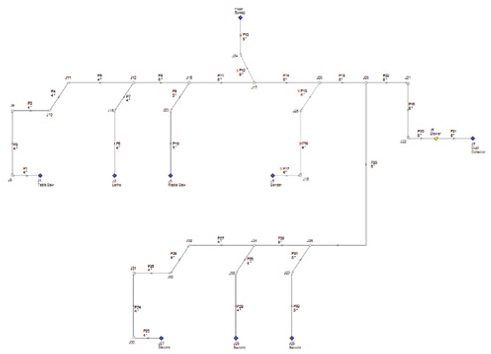
FIGURE 4. The example dust collection system now contains added equipment: a secondary table saw, lathe and radial saw
The two most remote pieces of equipment to the dust collector are the two table saws (upper table saw and lower second table saw). Reviewing how various system parameters change over a flow path gives great insight into how the system is performing and where you might have an issue. Figure 5 is an example of the velocity profile plotted from both table saws to the dust collector. At least half of the ductwork in both paths from each table saw is not able to operate at a sufficient velocity for properly carrying the dust particles. Cross-plotting system parameters with their minimum or maximum values allows one to easily see where design requirements are violated.
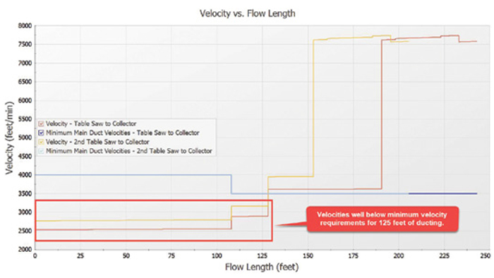
FIGURE 5. A plot of the velocity in the flow paths from each table saw to the dust collector from Figure 4. Velocities are well-below minimum velocities required in the first 125 ft (approximately) of ducting from each table saw
Overall, dust collection systems are a very important piece of the strategy for prevention and protection against process plant explosions and fires. Simple rules-of-thumb approaches to the design of dust collection systems are likely to fall short. Therefore, it is critical to perform a system-level analysis to determine design feasibility, as well as how to start modifying design and potentially the operation to meet the appropriate requirements. Flow-analysis software makes it easy to effectively analyze systems for their function and effectiveness. Ideally, software will be employed that can not only analyze design, but can also help with design by automatically determining proper duct sizes that will meet requirements.
Edited by Scott Jenkins
Reference
1. Chemical Safety and Hazard Investigation Board (CSB), www.csb.gov/imperial-sugar-company-dust-explosion-and-fire/. 2008.
Editor’s note: All diagrams courtesy of AFT
Author
 Ben Keiser is a technical sales manager for Applied Flow Technology (AFT; 2955 Professional Place, Suite 301, Colorado Springs, Colo.; Phone: 719-686-1000; Email: info@aft.com; Website: www.aft.com), a leading dynamic fluid-flow-analysis and waterhammer-mitigation software company located in Colorado Springs, Colo. Keiser holds a B.S.Ch.E. from the Colorado School of Mines. Keiser helps engineers understand how to design safe and efficient piping and ducting systems. His passion and expertise can be accessed around the world as he trains engineering teams how to efficiently preform flow analysis simulations to find optimized solutions.