Storage tanks containing hazardous materials require safety instrumented systems (SIS) to prevent overfills. Digital technology in the latest level-measurement devices used in SIS enables remote proof-testing, which provides significant advantages
At industrial facilities with tanks containing hazardous, flammable or explosive materials, the consequences of a safety incident, such as an overfill, can be catastrophic. To minimize risks, storage tanks must have in place robust safety instrumented systems (SIS) that are designed and implemented in compliance with relevant industry standards. Each SIS has one or more safety instrumented functions (SIF), which must be proof-tested periodically. This article discusses proof-testing of safety systems on storage tanks, and the potential advantages available when digital technologies are applied to storage-tank level measurement.
Safety standards
The relevant industry standards for SIS and tank safety are the following:
IEC 61511. The International Electrotechnical Commission’s (IEC; Geneva, Switzerland; www.iec.ch) IEC 61511 standard, which outlines best safety practices for implementing a modern SIS within the chemical process industries (CPI). IEC 61511 is an industry-specific adaptation of IEC 61508, which is an industry-independent standard for functional safety.
API 2350. The American Petroleum Institute’s (API; Washington, D.C.; www.api.org) API 2350 standard, which provides minimum requirements to comply with modern best practices in the specific application of large, non-pressurized aboveground petroleum storage tanks.
SIS include the level sensors, logic solvers and final control elements, in the form of actuated valve technology, for each of the SIFs — also known as safety loops — that they perform.
Proof-testing
Each SIF within a SIS must be proof-tested regularly. Proof-tests are operational procedures, conducted in accordance with the safety manual of an individual device, whose purpose is to uncover dangerous undetected failures (DUs). These are failures that prevent the device from performing its primary function and remain undetected by the device during normal operation. Proof-testing is a means of verifying that commissioned equipment already in operation will work correctly when there is a safety demand, and that the equipment achieves its required safety integrity level (SIL) for the application. Proof-testing involves testing each of the system’s components individually, as well as the complete safety loop. A safety loop’s probability of failure on demand (PFD) — that is, the risk of the device failing to perform its intended function — increases over time after commissioning. Performing a proof-test resets the PFD to a lower value and ensures that the safety loop provides the risk reduction it was designed to do (Figure 1).
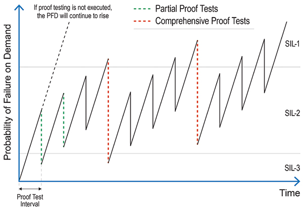
FIGURE 1. A safety loop’s probability of failure on demand (PFD) increases over time after commissioning. Performing a proof-test resets the PFD to a lower value and ensures that the safety loop provides the risk reduction it was designed to do
Proof-testing intervals
To create consistency in their approach to safety, many organizations abide by the requirements of both API 2350 and IEC 61511 with regard to proof-testing intervals. IEC 61511 specifies that the entire SIS must be proof-tested periodically, and the frequency of testing is determined by the PFD average of the safety loop. API 2350 states that continuous level sensors should be tested once per year, and point level sensors semi-annually. However, the interval between tests can be extended if there is a technical justification, such as the PFD calculation, to support it. Two types of proof-test — comprehensive and partial — may be performed in compliance with the standards.
Comprehensive proof-testing
Comprehensive proof-tests involve testing the entire safety loop using a single procedure, to ensure all of its parts are functioning correctly. Performing the proof-test will return the PFD of the safety loop back to, or very close to, its original level. Comprehensive proof-testing is carried out manually by multiple technicians in the field, with another worker stationed in the control room to verify the reaction of the system. There are two different ways in which a comprehensive proof-test can be performed.
In the first method, the level in the tank can be raised to the activation point of the level sensor being tested to provide proof that the instrument is functioning correctly. The danger of this approach is that if the device is a high-level sensor and it fails to activate during the test, this can lead to an overspill that would constitute a safety risk. This method is also time-consuming and can lead to the process being offline for an extended period, with significant cost implications.
The second approach is to remove the instrument from the tank and perform a simulated test in an alternative environment, such as a bucket, for example. A significant disadvantage of this method is that it can involve workers having to climb tanks to access an instrument, thereby putting their safety at risk (Figure 2). Performing proof-tests in this way is also prone to human errors, and can lead to tanks being taken out of service for an extended period, thus affecting profitability. In addition, if the instrument is removed from a tank containing a hazardous or unpleasant product, the test would be performed using water instead. This would fail to prove that the device would work in the specific application.
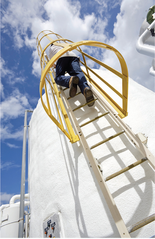
FIGURE 2. Traditional proof-testing methods on large tanks require operators to enter hazardous locations or work at height to access devices, which poses a potential risk to their safety
Partial proof-testing
A partial proof-test has reduced diagnostic coverage compared with a comprehensive proof-test because it is limited to exercising the electronics while the device remains installed. This can verify that there are no faults causing a higher output current than desired, preventing the device driving to low values, or issues preventing the device from driving to higher values. This type of testing may include one or several parts of the safety loop and will bring the PFD of a device back to a percentage of the original level and ensure that it fulfills its specified SIL requirement.
It is important to acknowledge that partial proof-tests complement — but do not replace — comprehensive tests. Because a partial proof-test detects only a percentage of potential failures, a comprehensive proof-test must eventually be carried out after a given time interval to return the instrument to its original PFD. However, performing partial proof-tests can still provide significant benefits for organizations. Partial proof-tests are quicker to complete, require less interference with operations, and crucially, they justify an extension of the time interval required between comprehensive tests, while still remaining within regulatory requirements. This then provides organizations with the freedom to schedule comprehensive tests around planned plant shutdowns, leading to improved plant efficiency.
Proof-test coverage
Smart level measurement devices for overfill prevention applications incorporate diagnostic software that identifies a failure and then takes the device to a safe state. However, some failures are not detected by the diagnostic software — these are the DUs that are revealed during proof-testing. Proof-test coverage is a measure of how many DUs can be detected by the proof-test. Comprehensive tests achieve the highest level of proof-test coverage, as they verify all three functional elements of the device — output circuitry, measurement electronics and sensing element — whereas a partial proof-test verifies one or two of them. However, a combination of partial proof-tests that covers all three functional elements will reach a similar proof-test coverage as a comprehensive test.
Minimizing the DU rate
DUs are measured as failures in time (FITs) and the DU rate is the number of DUs per 10 9 hours. Ideally, the DU rate should be as low as possible, and selecting an instrument that provides a high level of diagnostic coverage will minimize DUs, and therefore make the device less likely to fail in a dangerous way.
Safety lifecycle
IEC 61511 recommends the use of a functional safety lifecycle. This involves organizations analyzing hazard levels at their facilities based on risk assessments, selecting reliable level measurement devices for their SIS by considering DU rates, and checking the ongoing high reliability of devices and safety loops by performing regular proof-tests. Given the importance of DU rates, the reduction of DUs has been a specific aim in the design of the latest level-measurement technology. Advanced diagnostics capability enables the electronic and mechanical health of these devices to be monitored continuously, with the result that the number of DUs is significantly reduced.
Remote proof-testing
Proof-testing has traditionally been conducted on location. However, the digital technology available in modern level-measurement devices enables operators to perform partial proof-testing remotely instead, with the device remaining installed and overfill conditions being simulated to activate the detector and generate an alarm signal (Figure 3). This simulation eliminates the need for fluid to be moved into and out of the tank to perform the test. Simulations avoid the risk of spills, save a significant amount of time and eliminate the need for workers to climb tanks and be exposed to tank contents, thereby increasing worker safety and efficiency. The ability to perform partial proof-testing remotely has become a key selection criterion when implementing level measurement technology as part of a SIS.

FIGURE 3. The digital technology available in modern level measurement devices enables operators to perform partial proof-testing remotely from the comfort of the control room
Vibrating fork switches. The latest vibrating fork switches for level monitoring can be proof-tested remotely by issuing a HART command (Figure 4). Upon receiving the command, such a device would enter test mode, which cycles the output through wet, dry and fault states, then returns to normal operation. If the proof-test detects an issue, this is reported upon its completion. Using this functionality, the proof-test can take less than one minute to complete, because the instrument remains installed and does not need to be immersed.
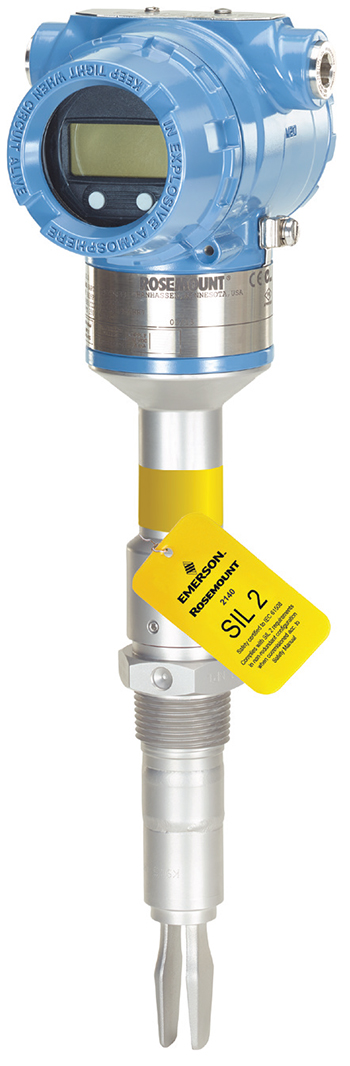
FIGURE 4. The latest vibrating fork switches can be remotely proof-tested by issuing a HART command. Using this functionality, the proof-test can take less than one minute to complete
Radar devices. Radar is generally the first choice of level measurement technology in a tank gauging system, and the latest non-contacting radar level gages can be proof-tested safely and remotely from the comfort of a control room using powerful and easy-to-use inventory management software. Built-in functionality guides an operator through inputting a straightforward sequence of settings and commands from their interface, enabling a device to be proof-tested in under five minutes (Figure 5). This achieves considerable benefits in terms of reducing risk and errors, saving time, and increasing worker safety and efficiency.
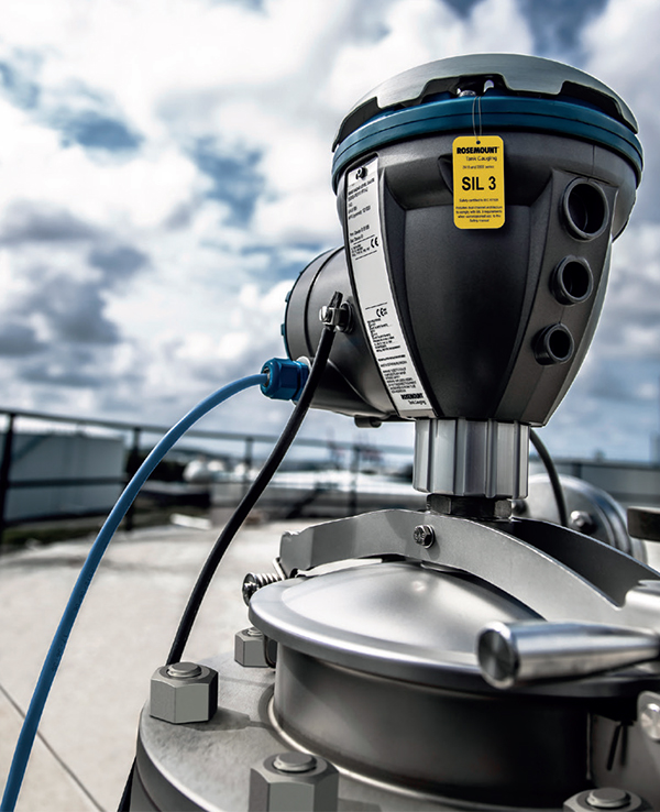
FIGURE 5. Powerful and easy-to-use inventory management software enables the latest non-contacting radar level gages to be proof-tested safely and remotely from the control room in under five minutes
Reference reflectors. Typically, guided-wave radar sensors do not feature overfill simulation technology. However, recognizing the benefits that this feature would provide has led to the introduction of an automated high-level alarm testing function in the latest smart devices. The correct functioning of the high-level alarm can be verified through the use of an adjustable reference reflector fitted to a device’s probe at a desired height to generate a unique echo signature. The device constantly tracks the reflector echo to determine if the level is above or below the alarm limit. A “test” function built into the software verifies that the device has been correctly configured and is correctly tracking the reflector echo. It also confirms that the alarm loop is working, with a high-level alarm being displayed in the control room.
Because this automated testing function does not require the device to be removed from the tank, or the level in the tank to be manually raised, it increases the safety of both the plant and workers. Verification reflector functionality reduces the risk of accidental spills and enables the high-level alarm testing process to be completed more quickly. It also tests the loop from the device to the distributed control system (DCS), as well as the device itself.
Simulated reference reflectors. The high-level alarm can also be verified using a simulated reference reflector, whereby an artificial digital echo is inserted into the radar signal. This artificial digital echo triggers the high-level alarm when detected, thus eliminating the need to have a physical reference reflector. One benefit of this approach is to avoid having a tank obstruction. Performing the test with either a physical or simulated reference reflector as part of a combination of partial proof-tests can achieve a proof-test coverage factor of 73%.
Reporting proof-test results
Both IEC 61511 and API 2350 require organizations to provide written procedures, schedules and documentation of proof-testing. This documentation must include instructions for maintaining safety during the proof-test, as well as actions to be taken upon detection of a fault. Records certifying that tests were completed must be maintained. These should include descriptions of the tests performed, the names of the people that performed them, the dates when they took place, and their results. By providing the reporting functionality to support these requirements, the latest smart level measurement devices and their supporting software ensure compliance with the standards, while simplifying the documentation and auditing process.
Edited by Scott Jenkins
Author
 AnnCharlott Enberg is the global functional safety manager at Emerson (8000 Florissant Ave., St. Louis, MO 63136; Phone: (314) 553-2000; Email: AnnCharlott.Enberg@Emerson.com; Website: www.emerson.com/proof-testing). Enberg began working in the functional safety field 20 years ago, as chief executive for SILTECH AB. She was then business unit director for DEKRA AB and SRE site responsible process safety engineer for Akzo Nobel AB. Enberg is now the global functional safety manager at Emerson. Her focus has been to work closely with the industry to ensure safe processes in engineering systems through hazard and operability (HAZOP) studies, failure mode effects analysis (FMEA) and layers of protection analysis (LOPA), to ensure risk reduction and optimize personal human design processes. Enberg’s goal is to continue to make safety instrumented systems devices easier to implement, and to increase safety globally. Enberg was selected as Global Manager of the Year in 2020 by the International Association of Top Professionals (IAOTP).