Successful operation of safety valves in steam systems requires careful adherence to established industry standards for installation and design
One of the most critical safety devices in a steam system is the safety valve. Figure 1 is an illustration of a typical safety valve, and Figure 2 shows a valve in context on a steam line. Safety valves protect personnel, equipment and property from potentially dangerous high temperatures and forces caused by excessive steam pressure in the steam system.
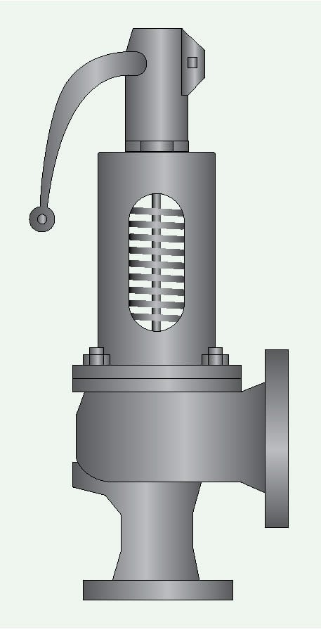
FIGURE 1. A safety valve used in a steam system should meet the rigorous requirements of the ASME Boiler and Pressure
Vessel codes
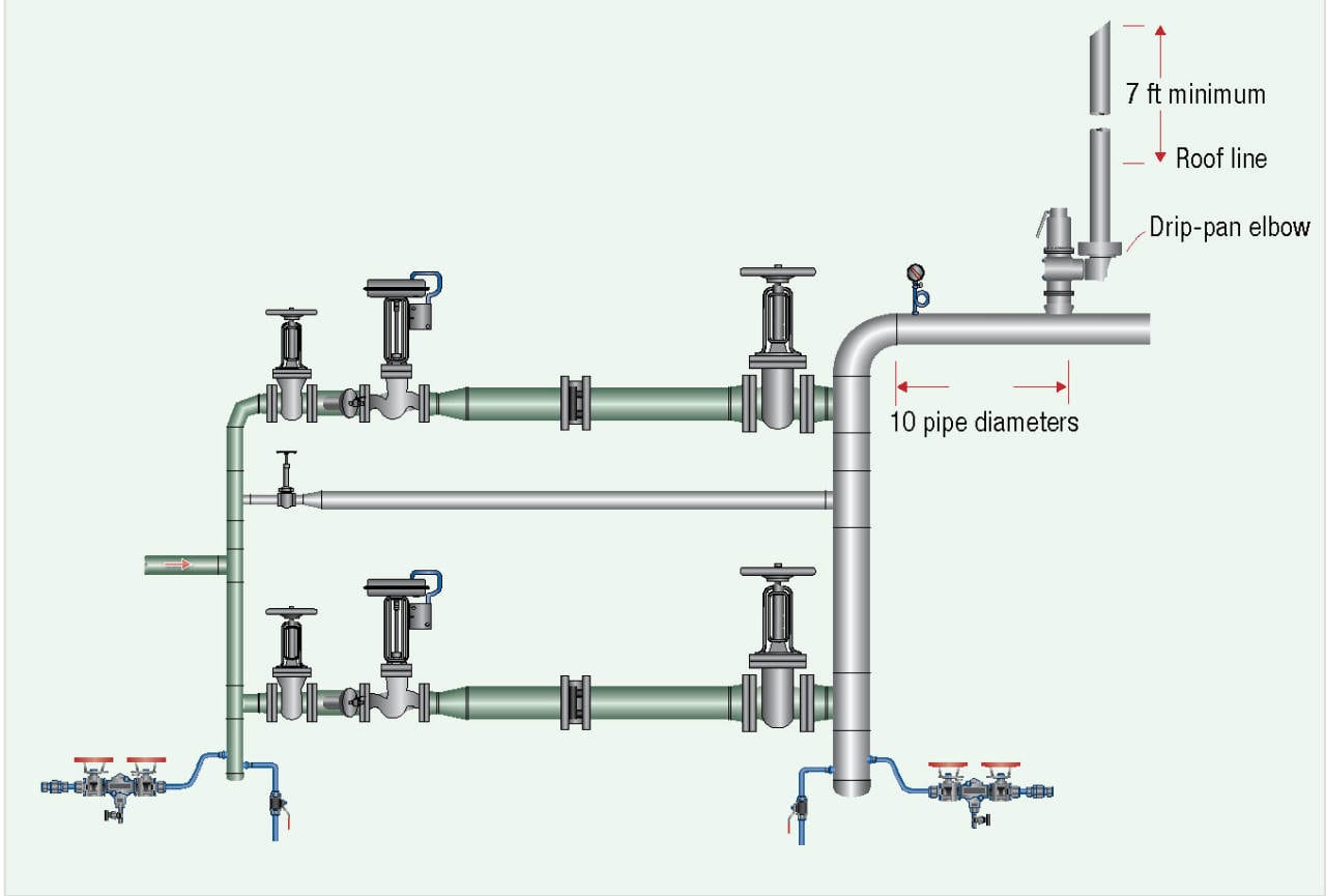
FIGURE 2. A safety valve in a steam line protects against potentially dangerous situations, including excessive steam pressure and high temperatures
Steam safety valves are required by industry standards, as well as insurance and corporate mandates. Therefore, it is important that the safety valve be properly sized and installed to meet all code requirements.
The code that establishes the requirements for steam safety valves is written by the American Society of Mechanical Engineers (ASME; New York, N.Y.; www.asme.org). ASME, through its committees, has published and continues to update the Boiler and Pressure Vessel Codes (BPVC) for safety valves. It is the responsibility of plant personnel — primarily the plant’s steam team — to know which codes apply to the different parts of the steam system. The proper selection, installation and use of safety valves require a complete understanding of the ASME code and any additional requirements adopted by insurance companies or the local jurisdictional authority.
Documenting safety valves
Maintaining a well-documented database that contains up-to-date records of all safety valves in the steam system is necessary to ensure reliable, safe plant operation. The database should include all relevant information about all safety devices. The plant can rely on this database as it conducts yearly inspections of the Section I and Section VIII BPVC safety valves. The safety valve database should always be updated with the yearly information from inspections and changes based on plant standards and insurance company recommendations, as well as federal, state or local government requirements.
Sizing guidelines
When sizing safety valves, plants should follow a number of guidelines to avoid failures and to comply with applicable codes.
First, the setpoint for the safety valve should be set so that there is at least 10% between the operating system pressure and the safety valve set pressure. This will prevent the safety valve from operating in the simmer mode, which the code does allow.
Second, the plant should choose a valve capacity based on the control valve’s maximum flow. To do so, engineers should calculate the inlet steam pressure (PI) at the maximum steam pressure, which is the safety valve setting of the steam supply source. The engineer should not calculate using the steam system’s nominal operating pressure.
In many cases, it is not possible to install a single safety valve because of high steam capacity or physical limitations. An acceptable alternative is to employ multiple safety valves on the same steam system. The safety valves can have different setpoints so long as the setpoints are below the steam system’s maximum design pressure. The total steam capacities must be equal to or greater than the maximum steam flow to the system to ensure that they never exceed the maximum steam pressure.
Keep in mind that the total capacity might change depending on the location of the safety valve. When considering a safety valve downstream of a steam-pressure-control valve, the total capacity of the safety valve at the setpoint must exceed the steam control valve’s maximum flow capacity (the largest orifice available from that manufacturer) if the steam valve were to fail in the fully open position.
When a safety valve is installed downstream of a control valve or a regulating valve, and a bypass valve is installed, the bypass valve must always have a smaller diameter than the control valve to ensure it has a lower flow coefficient (Cv) than the control valve. If the bypass is the same size as the control valve, then the safety valve has to be sized for the valve (control valve or bypass) with the higher Cv.
Finally, the plant should adjust the set pressure of the safety valve to be equal to or below the maximum allowable working pressure (MAWP) of the component with the lowest MAWP in the steam system. This includes, but is not limited to, steam boilers, pressure vessels, equipment and piping systems. In other words, if two components on the same system are rated at different pressures, the safety device protecting the steam system for both devices must be set at the lower of the two MAWPs.
Installation guidelines
Figures 3 through 5 show three different types of safety valve installations: Figure 3 shows a typical installation; Figure 4 depicts a safety valve installed after a pressure-reducing valve; and Figure 5 illustrates a safety valve installed on a heat-transfer process. No matter which purpose the safety valve serves, the foundation of a successful installation is proper preparation of the steam system. Engineers must ensure the steam system is clean and free of any dirt or sediment. They can prepare the steam piping before installing it or, after installation, by conducting controlled steam blowthroughs.
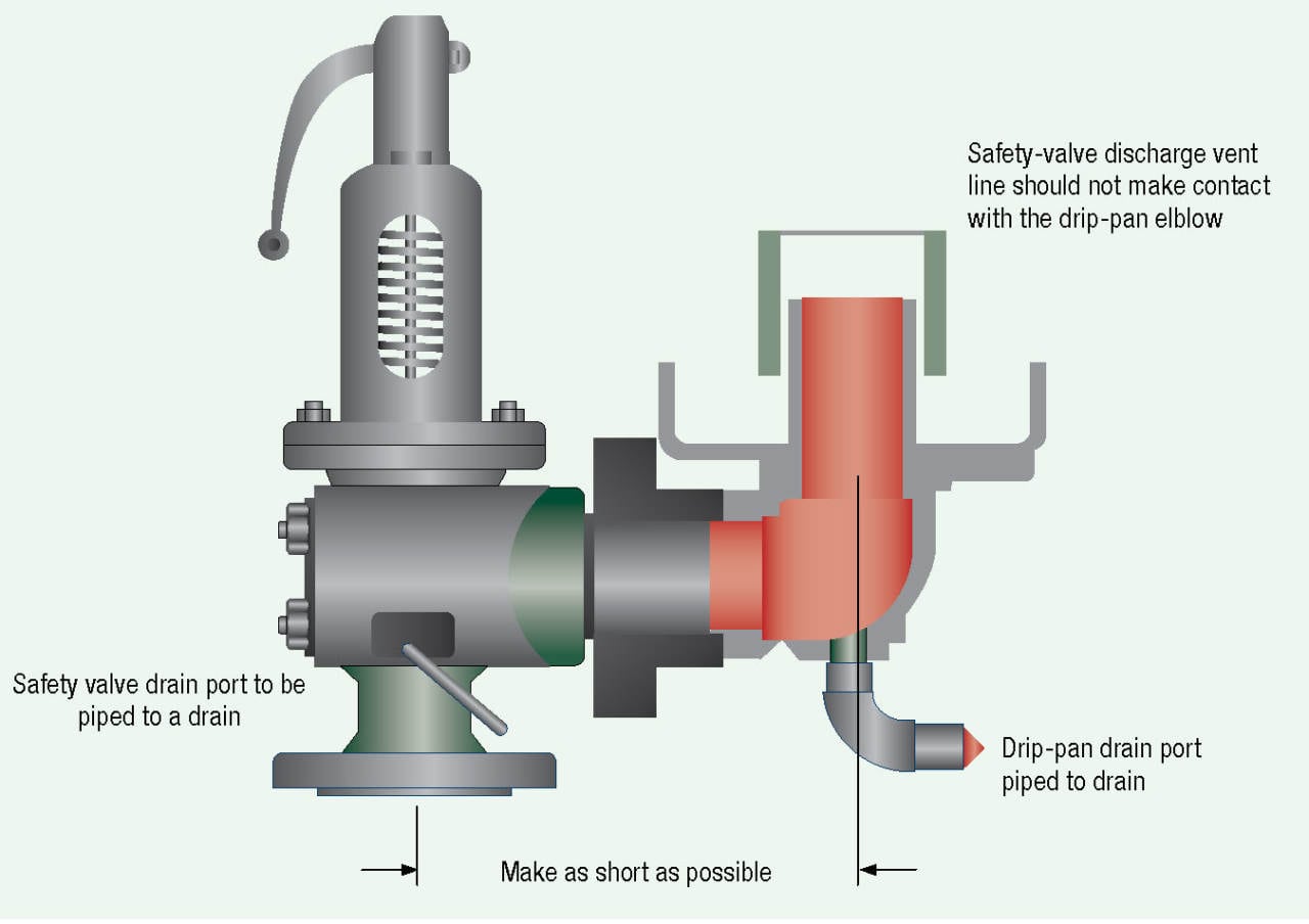
FIGURE 3. There are many aspects to consider when installing a safety valve into a typical steam-system application
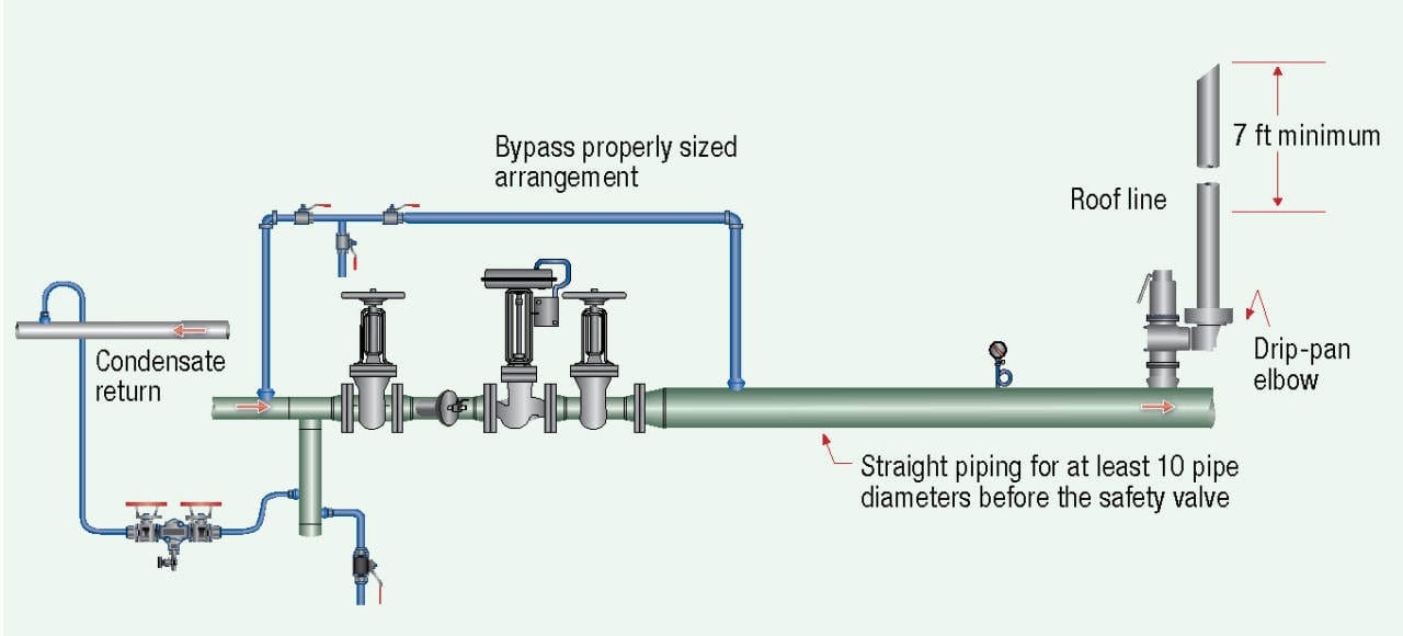
FIGURE 4. Safety valves can be installed downstream of a pressure-reducing valve, as shown in this
illustration
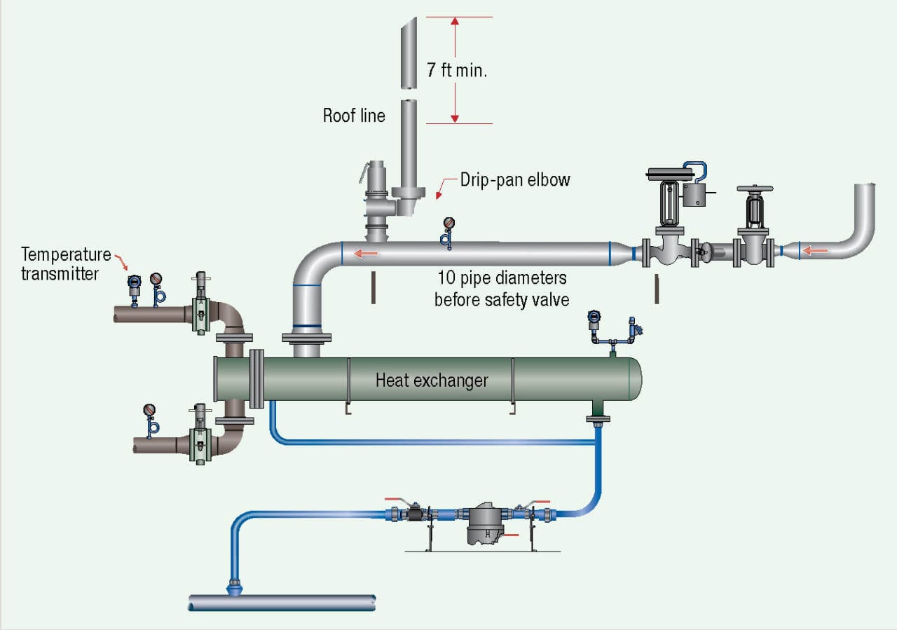
FIGURE 5. Several special considerations should be understood when installing safety valves into
heat-transfer applications
Plants must keep a number of parameters in mind when choosing a location for the installation. Safety valves should be connected to the steam line independent of any other type of connection. Also, the safety valve should be located as close as possible to the steam line or vessel. Additionally, they must be installed at least 10 pipe diameters downstream of any valve, elbow or other component that could disrupt the steam flow. Finally, safety valves must be mounted vertically. The valve’s spindle must be in an upright position and no more than 1 deg away from vertical.
In addition, engineers should review the context of the valve to make sure it does not interfere with safety valve operation. First, check the steam line or pressure vessel. It should be free of any vibration or waterhammer that could change the set pressure of the safety valve. Second, review the inlet steam piping. The inlet steam piping to the safety valve must be equal to or larger than the safety valve inlet connection. For example, if the safety valve has a 3-in. inlet connection, the piping from the vessel or header should be 3 in. or larger. Third, look for any intervening shutoff valves between the safety valve inlet and the steam component. Shutoff valves could isolate the safety valve from the system or could restrict the steam flow to the safety valve. Finally, inspect for plugged or capped drains or vent openings on the body of the safety valve. The purpose of the drain or vent openings is to allow any liquid that might accumulate above the discharge valve to evacuate properly.
Safety valve flanges should be installed according to the appropriate bolt torque specifications, procedures and torque patterns.
When using more than one safety valve, the discharge vent piping must be sized to accommodate the full flow of all safety valves in a fully open position simultaneously when there is no backpressure on the safety valve outlets. For multiple safety valve installations using a single connection, the internal cross-sectional area of the inlet should be equal to the combined inlet areas of all the safety valves.
All safety valves should use a purchased or custom-made drip-pan elbow on the safety valve outlet. Drip-pan elbows improve the performance of safety valves in two ways: they isolate the safety valve from the weight of the safety-valve vent piping; and they change the steam flow at the outlet of the safety valve from horizontal to vertical.
When installing a drip-pan elbow, engineers should remember that the steam will not escape from the drip-pan elbow configuration if the safety-valve discharge vent line is properly sized. In addition, the safety-valve discharge vent pipe should not touch the drip-pan elbow. The discharge vent piping should be supported independently from the safety valve and drip pan elbow assembly to prevent undue stresses on the safety valve. Furthermore, the drains on the drip-pan elbows are designed to collect any condensed liquid and rain, and to allow flow to move safely away from the safety valve, so the drip-pan elbows should not be plugged.
Plants should also mind one additional caveat when it comes to valve installation: be aware of the temptation to tamper with safety valve settings. Safety valves are set, sealed and certified by the manufacturer or an authorized and certified assembler to prevent tampering by unauthorized personnel. If the wire seal on the safety valve is not intact, the valve is no longer in compliance with the code, and it should be replaced as soon as possible.
Discharge vent piping
Plants must follow several principles when installing safety-valve discharge vent piping. First, the diameter of the discharge vent pipe must be equal to or greater than the safety valve outlet. Second, the discharge vent line should be sized to avoid creating any backpressure on the safety valve during the discharge mode. Figure 6 depicts an incorrect installation. The discharge vent line is firmly attached to the safety valve outlet, which will put stress on the safety valve. Third, the plant should minimize the length of the discharge vent pipe. A rule of thumb is that if the discharge vent pipe exceeds 30 ft and has more than one elbow, then the discharge vent piping must be increased in size to prevent backpressure on the safety valve.
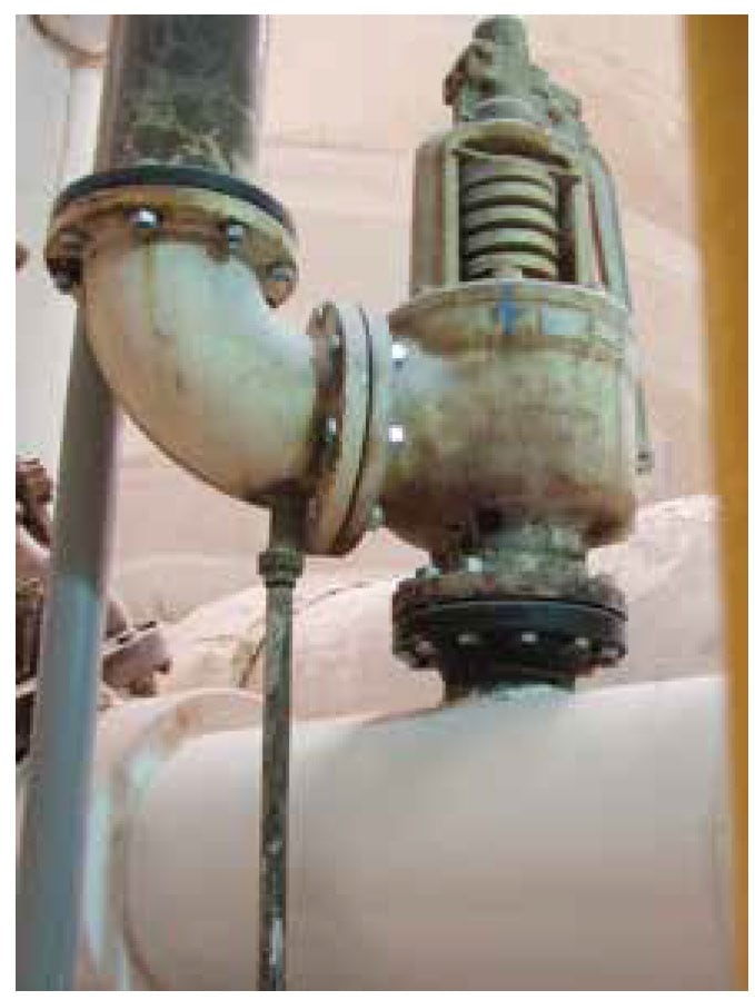
FIGURE 6. In this photo, the discharge vent line is attached directly to the safety valve, which is an incorrect configuration that can result in excess stress being placed on the valve body
Finally, the discharge outlet of the vent pipe should be piped to the closest location where free discharge of the safety device will not pose any safety hazard to personnel. The typical safety-valve discharge point is above the roofline or above the plant’s operating unit. The safety-valve discharge vent should be no less than 7 ft above the roofline or the operating unit, as Figure 7 shows. The top of the discharge vent line should be cut at a 45-deg angle to dissipate the steam discharge thrust, to prevent capping of the pipe and to visually signify to plant personnel that it is a safety valve vent line. Again, Figure 6 is an incorrect installation since the discharge vent line is firmly attached to the safety valve outlet, which will put stress on the safety valve. Never attach the safety valve discharge vent piping directly to the safety valve, because this will place undue stress and weight on the safety valve body and change the set pressure of the safety valve. A very short section of vent pipe must be used to connect the safety valve drip pan elbow to the safety valve if the drip pan elbow is not directly connected to the safety valve.
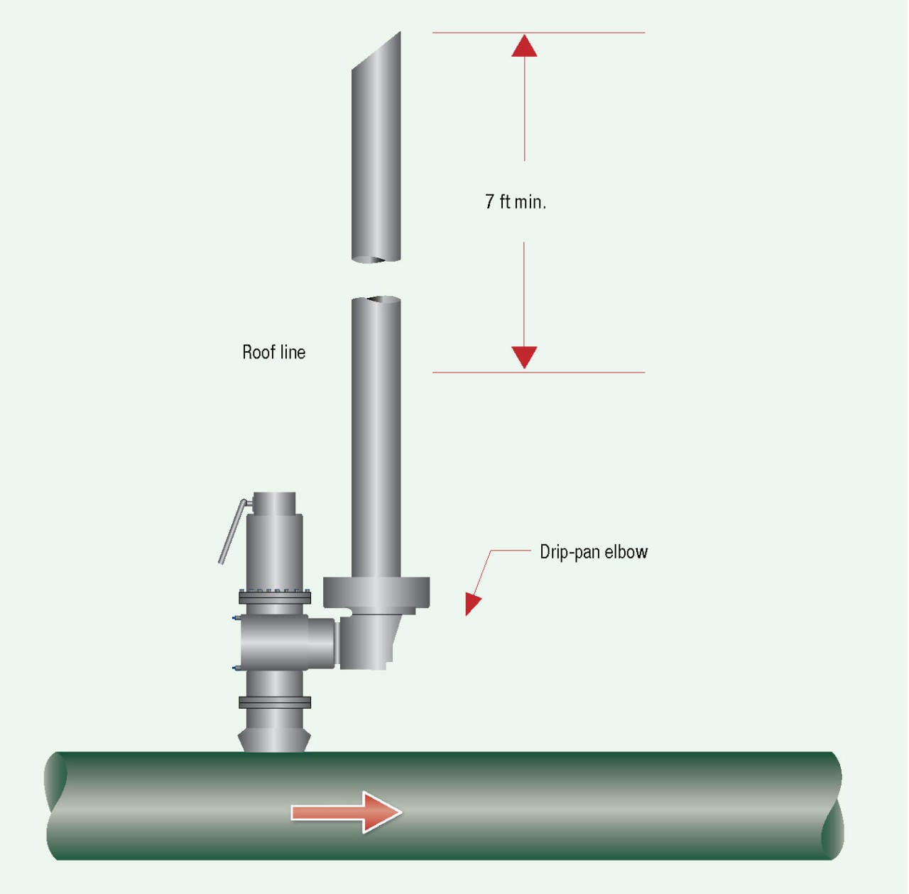
FIGURE 7. The safety valve discharge vent line should be at least 7 ft above the operating unit
Best practice roadmap
There are three primary steps to a successful safety valve operation. First, establish plant standards for safety valve installation and selection. Second, add all safety valves to a database. Finally, review all safety valves periodically, depending on plant standards, insurance company recommendations, and federal, state, or local government requirements.
Edited by Mary Page Bailey
Author
 Kelly Paffel currently serves as technical manager at steam engineering firm Inveno Engineering, LLC (7320 East Fletcher Ave, Tampa, FL 33637; Phone: 239-289-3667; Email: kelly.paffel@invenoeng.com; Website: www.invenoeng.com). Paffel has 41 years of experience in steam and power operations and is an experienced lecturer who has published many technical papers on the topics of steam system design and operation. He is known for writing “Steam System Best Practices,” which are used by plants and engineers globally to ensure proper operation of steam and condensate systems.