Temperature measurement is critical in many types of process equipment, including reactors, distillation columns, furnaces, heat exchangers, evaporators, boilers and more. Among the most widely used instruments for measuring temperatures in chemical process industries (CPI) operations are resistance temperature detectors (RTDs). This one-page reference describes the principles behind the operation of RTDs, and their advantages and limitations.
RTD operation
RTDs are temperature sensors that operate on the principle that a material’s electrical resistance changes with temperature in a predictable way. When an RTD is supplied with a constant current, the resulting voltage drop can be measured and the resistance calculated. The highly predictable relationship between RTD resistance and surrounding temperature allows the temperature to be determined accurately and reproducibly.
RTDs can be connected in a two-, three-, or four-wire configuration, in which current is conducted through the RTD and the resulting voltage measured. The two-wire configuration is the simplest, but also the most prone to error, because the two connecting lead wires add some resistance to the RTD (Figure 1). This introduces error. The three-wire setup is similar, except that a third wire provides compensation for the lead resistance. This requires either a three-wire compensating measurement unit or actually measuring the contribution from the third wire and subtracting it from the overall measurement. In the four-wire method, current is sourced on one set of leads, while the voltage is sensed on another set of leads to eliminate the test lead resistance from the measurement.
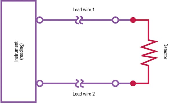
FIGURE 1. A two-wire RTD detects temperature-dependent changes in resistance, but must be corrected for resistance added by the lead wires
Temperature-sensitive materials used in the construction of RTDs include platinum, nickel and copper, with platinum being the most common. An important characteristic of an RTD material is its temperature coefficient of resistance (TCR), which determines the temperature-resistance relationship. A common industry standard is the platinum 3850 ppm/K, where the resistance of the sensor increases 0.385 ohms for each one degree-Celsius increase in temperature.
Physical principles
The Callendar-Van Dusen (CVD) equation is used to define the relationship between resistance (R) and temperature (T) of platinum RTDs. It is also used in the international standard IEC 60751 (International Electrotechnical Commission standard on industrial platinum resistance thermometers and platinum temperature sensors). Originally developed by British physicist H.L. Callendar, and refined by M. S. Van Dusen, the CVD equations are used to determine the temperature-resistance behavior for platinum resistance temperature detectors. The CVD coefficients A, B and C are temperature-dependent, and can be determined for a specific RTD by using calibration techniques in a laboratory. The CVD equation is shown in Equations (1) and (2).
R(T) = R0 [1 + AT + BT2 + C( T − 100) T3 ] (from –200 to 0°C) (1)
R(T) = R0 (1 + AT + BT2) (from 0°C and 661°C) (2)
As an example, the coefficients for a Pt100 resistor (a platinum constructed, 100-Ω RTD) according to the IEC751 and international temperature scale (ITS-90) standards are given here:
R 0 = 100 Ω; A = 3,908 × 10–3 °C –1
B = –5,775 × 10–7 °C –2
C = –4,183 × 10–12 °C –4.
Another coefficient, α, is a linear parameter defined as the normalized slope between 0 and 100°C.
Advantages and limitations
RTDs have good accuracy, precision and longterm stability. Concerns about maintenance, cost and accuracy are the primary drivers in the shift to the use of RTDs from thermocouples. Thermocouples will have a lower initial cost, when compared to RTDs, but the value of the accuracy and stability offered by RTDs often exceeds the initial cost savings of installing a thermocouple. With thin-film RTDs, as opposed to wire-wound designs, the cost difference is smaller.
Thermocouples may still have to be used in situations where process temperatures exceed the limit of an RTD (650°C), or when a very fast response is needed. However, there are some fast-response RTD designs available that may also negate the use of thermocouples in the latter case. Thin-film RTDs are typically limited to temperatures of 260°C, while wire-wound elements can withstand temperatures up to 650°C. Also, due to the construction of the sensing element, thin-film RTDs do not perform as well in environments where high levels of vibration or severe mechanical shock occur.
References
1. Cushing, M., Temperature Measurement: Trends and Technologies, Chem. Eng., June 2015, pp. 42-45.
2. Cigoy, D., Resistance Temperature Detectors, Control Engineering, www.controleng.com, Nov. 1, 2005.
3. AZO Materials. Resistance Temperature Detector (RTD): Principle of Operation, Materials, Configuration and Benefits, published online, www.azom.com, 2010.
3. Temperatures.com Inc., https://www.temperatures.com/rtds.html, Southampton, Pa., accessed Sept. 2018.
4. Omega Engineering. An Introduction to RTD sensors, online guide, www.omega.com/prodinfo/rtd.html, accessed September, 2018.