To obtain a representative sample for particle size characterization, adhere to the golden rules of sampling and follow these best practices
In the chemical process industries (CPI) it is often necessary to verify material specification at various points in the process. In that effort, it is usually impossible — or at the very least impractical — to measure the whole production. Instead, small samples must be extracted from a parent population. Such is the case in particle size characterization of bulk solids, process streams and slurries.
While truly representative sampling has long been an important goal, a number of current trends are driving the incentive for rapid implementation of top-notch sampling strategies to be the standard, rather than the exception. These trends include the ever-increasing demand for superior material quality in the high-technology industries, more-stringent pharmaceutical regulations and higher environmental standards, to name a few.
Unfortunately many sampling strategies in use today do not take into account the most modern sampling theories, which leads to inaccurate test results and unrealistic material specifications that are impossible to verify properly.
The best practices outlined in this article provide guidelines for collecting representative samples from most solids handling and processing equipment and then reducing the sample to the proper size for the analytical technique used in the measurement. In addition, an assessment of sampling errors, based on simple statistical theories, illustrates the pitfalls of sampling methods.
One of the everyday examples of sampling that all of us can relate to is when a medical doctor orders blood to be drawn for routine laboratory analysis. In this example, we can all appreciate the two main, necessary characteristics of the sample:
1. That a relatively small sample is taken (much smaller than the total available)
2. That the sample be representative of the whole (so that the correct diagnosis can be made)
Although both points are extremely simple concepts, a great deal of diligence is usually necessary to achieve them. Careless sampling of powders or slurries often results in a faulty conclusion, regardless of whether good analytical techniques are employed. In that respect, the first item that should be considered for a particle-characterization study is a sampling protocol that insures a representative sample of the proper size.
Statistics of sampling
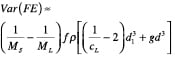
The first necessary step for a good sampling program is to define the sample that is needed and clearly specify how the sample is taken, including equipment specification. It is important to keep in mind that in particulate material sampling, the best we can ever achieve is a random sample where all particles within the parent population have an equal chance of being sampled, thereby assuming that no systematic bias exists in the sampling process. Since there is no such thing as two identical samples, a perfectly extracted sample (random sample) will always be inflicted by a residual error, called the fundamental error ( FE), as first postulated by Gy [ 1]. This is due to the heterogeneity of any particulate sample that has a distribution of particle sizes. This notion that individual particles are not identical is referred to as constitutional heterogeneity (CH). The higher the upper end of the distribution, the higher the heterogeneity. The Gy sampling theory can estimate the variance of this fundamental sampling error due to the CH, using Equation (1), [ 2]:
 (1)
(1)
Where M S is the mass of the sample, M L is the mass of the parent population from which the sample is taken, ƒ is a shape factor (0.5 for spheres, 1 for cubes, 0.1 for flakes), ρ is the particle density, c L is the mass fraction of material in the size class of interest, d 1 is the average particle diameter in the size class of interest, g is the granulometric factor [ratio of the diameter corresponding to the 5th percentile of the size distribution to the diameter corresponding to the 95th percentile of the size distribution ( d 05/ d 95)], d is the diameter corresponding to the 95th percentile of the distribution ( d 95). This allows the calculation of the fundamental error for any size class in a distribution. If the mass of the parent population is much greater than the sample mass, the term 1/ M L can be dropped from the equation. A few important highlights from the above equation: 1. The variance of the fundamental error decreases as the sample size increases. Since the variance is equal to the square of the fundamental sampling error, the fundamental sampling error decreases in proportion to the square root of the sample mass 2. The variance of the fundamental error is a strong function of the coarse end (95th percentile) of the size distribution as dictated by the d 3 term. The above equation can easily be rearranged to provide the minimum sample mass to be used in an analysis. The sample mass estimate is the minimum sample size, since additional sources of error will contribute to the variance of the total sampling error. It should be noted that these additional contributors can be minimized through good sampling practices, and therefore are controllable to a large extent. Gy broke down the total sampling errors into seven basic components as listed in Table 1. 
The mass required to meet a product specification is related to the inherit degree of heterogeneity in the material and the desired level of accuracy and precision. In addition to sampling error, analytical error will also add to the uncertainty of the measurement. With modern particle-characterization instrumentation, the sampling error will typically become much larger than the expected analytical error as the top end of the distribution (95th percentile) exceeds 100 microns. Gy defined each of the seven error components as an additive model where the variance of the total error is as follows:
TE = FE + GE + CE 2 + CE 3 + DE + EE + PE (2)
If correct sampling practices are utilized, the terms GE, CE 2, CE 3, DE, EE, and PE are minimized, and are much smaller that the FE term, for particles sized greater than about 100 microns. This minimization of the sampling error can only be accomplished through appropriate selection of sampling equipment for all phases of the sampling and sub-sampling process. For smaller particle sizes, where the heterogeneity of the system decreases as the third power of particle size, sampling typically becomes less of an issue, and analytical errors take over. Table 2 outlines the basic steps for correct sampling.
Grab samples should not be used even if one attempts to mix the bulk specimen prior to sampling — for example, bulk bags or perhaps a sample brought to the laboratory. It is simply not possible to obtain a homogeneous mix from blending alone, and therefore such a practice should not be used to properly minimize grouping and segregation errors. Pitard [ 2] showed that the variance of the grouping error can be compared to the variance of the fundamental error as follows:
![]() (3)
(3)
As a rule of thumb, at least 30 sample increments ( N) are recommended to minimize GE errors.
Example of a Sampling problem, with solution
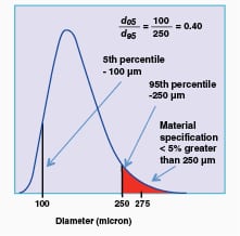
After several customer complaints, an engineer is assigned the responsibility of setting up a sampling protocol for a ground product that frequently does not meet the specification that no more than 5% of the mass, or volume distribution should be greater than 250 microns (Figure 1). This product is sold in lots consisting of several tons. This specification should be measured at the 99% confidence level. This product has a density of 2.5 g/mL. Assuming that correct sampling techniques were used to obtain a random sample, what is the minimum sample size that needs to be collected and analyzed?
Solution:
 |
1. Since the mass of the sample is much smaller that the mass of the lot, the equation for the fundamental error estimation [Equation (1)] can be rearranged as follows to solve for the minimum sample mass
2. Measure the size distribution on a volume, or mass basis to obtain the diameters corresponding to the 5th and the 95th percentile (Figure 1)
3. The 99% confidence level implies that the value of FE is 0.01. The variance of the fundamental error, Var(FE), is 0.01 2, or 0.0001. The shape factor (ƒ) can be set at 0.5, assuming that the particles can be approximated by spheres. The particle density (ρ) is 2.5 g/cm 3. The fraction of material in the size class of interest c L is 0.05 (5% > 250 microns). The average diameter in the size class if interest (d 1) can be taken as 275 microns (see Figure 1). The granulometric factor (g) is defined as d 05/d 95 (see Figure 1) is 0.40 for this distribution. Finally, d, defined as the 95th percentile of the distribution (see Figure 1) is 250 microns. Changing all units to CGS units to obtain the sample mass (M S) in grams, we obtain the following:
Please note that not only a sample of 4.8 g is needed, but an analysis technique that can analyze the whole sample needs to be utilized. â
Correct Sampling
Correct sampling implies following a few simple rules throughout the sampling process as well as using appropriate sampling tools to minimize the errors identified in the previous section. Correct sampling practices include the following:
• Taking many samples at regular or random time intervals (>30 samples), and sub-dividing into smaller samples for analysis to minimize grouping and segregation error ( GE)
• Using correctly designed sampling tools to minimize delimination and extraction errors ( DE and EE).
• Using common sense and diligence to minimize sample preparation and analysis errors (avoid particle settling, agglomeration, dissolution, and swelling) ( PE)
In this section, we will introduce sampling equipment designed to sample from various solids systems including static bulk materials, gravity flow systems, mechanical conveying systems, pneumatic conveying systems, solids-processing unit operations and slurry systems. The sampling techniques in different systems are discussed and recommendations for proper sampling are provided.
Sampling process overview
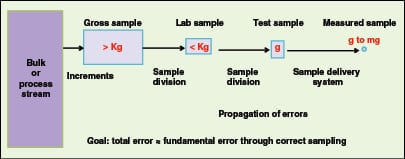 |
There are usually several stages in particulate matter sampling, and it is of paramount importance to maintain the integrity of the sample until the analysis is carried out. Figure 2 takes us through the stages of a sampling process. Several increments are taken from the bulk lot using properly designed sampling equipment as outlined in the next section. The gross sample may be too large to be sent to the laboratory, and may need to be reduced to a more practical weight. Depending on the measurement technique, and the amount of sample required by the instrument sample delivery system, the laboratory sample may need to be further sub-divided to the test sample to be used in its entirety by the instrument. Even at the laboratory-sample level, which is the last step before analysis, the common practice of simply scooping material out of the container is likely to introduce bias. The overall goal of any sampling procedure is simple: it is to obtain a sample with a total sampling error similar to that expected from the fundamental sampling error, which is solely governed by the heterogeneity of the material — grab sampling at any level will almost guarantee that this goal will not be achieved.
Gross sample extraction
Consistent with Gy’s sampling theories, Allen [ 3] independently proposed two “Golden Rules” of sampling:
1. Sample a moving stream — sampling of bulk solids at rest should be avoided.
2. The whole of the stream of powder should be taken for many small increments in time in preference to part of the stream being taken for the whole time.
Applying Gy’s principles and Allen’s recommendations, extraction of a gross sample consists of properly extracting several increments from the parent lot during processing or handling using properly designed tools. Each increment can be defined as the group of particles extracted from the parent lot during a single operation cycle of the sampling device. The final gross sample should consist of at least 30 such increments.
Static material sampling
Ideally, the sampling should have been carried out before the material became a static bulk, which is much more difficult to correctly sample. The degree of inhomogeneity will depend on the powder’s history. In the case of free-flowing material, it is a safe bet to assume segregation has taken place during the transfer, and for non-free flowing material, the degree of inhomogeneity will largely depend on its history.
The inherent problem with sampling static material is that no equipment exists that can take a sample where every particle has an equal chance of being sampled. There will always be parts of the bulk that will not be accessible to the sampler.
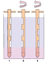 |
The workhorse of the bulk sampling domain remains the thief sampler (Figure 3), which provides several increments taken at random throughout the bulk material. This device consists of a co-axial outer sleeve and an inner hollow tube with matching grooves to allow powder flow in the core of the inner cylinder. In the first step of the sampling procedure, the inner tube is rotated so that the matching groves are on opposite sides, then the probe is inserted in the powder. The second step consists of twisting the inner tube to align the two sets of grooves, thereby allowing powder to flow into the sampler. Thirdly, the inner tube is twisted to lock the powder into the sampler, which is then withdrawn from the bulk. This procedure is repeated several times to extract several increments to make up the bulk sample ready for splitting. The shaded region at the bottom of Figure 3 indicates the region where there is no chance of sampling, which illustrates a weakness of this device. Another source of error to be aware of when using this type of device occurs as the material is being displaced down by the probe moving through the bulk material, thereby causing segregation and preventing equal probability for all particles to be sampled.
Sampling free-falling streams
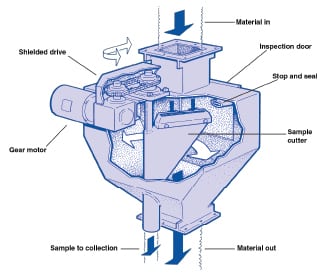 |
The rotary chute sampler, also referred to as the Vezin sampler, is a multi-purpose device that collects representative samples from materials (dry powders or slurries) that are free-falling from pipes, chutes or hoppers. This sampler is generally a good choice for installation on loading and unloading equipment, or at the entrance or exit of material transfer equipment. Various versions of the Vezin sampler are available in several sizes from multiple manufacturers. This device, shown in Figure 4, operates by one or more cutters revolving on a central shaft, passing through the sample stream and collecting a fixed percentage of the total material. A Vezin sampler is totally enclosed to minimize spillage or leakage problems. The area between the sample cutter and the discharge chute is sealed to prevent possible contamination or sample loss.
As a rule of thumb, incremental extraction errors can be minimized by limiting the cutter speed to 0.6 m/s, an inner-wall sampler three times the particle diameter (3 d) for coarse material, where d > 3 mm, and at least 10 mm for finer material.
Sampling from gravity flow
 |
As shown in Figure 5, gravity flow can be any free-flowing powder or slurry from a conveyor, hopper, launder or unit operation under the influence of gravitational forces. When sampling in such systems, each increment should be obtained by collecting the whole of the stream for a short time. The width of the receiver should be made at least 10 mm or three times the diameter of the largest particles — whichever is larger. The volume of the receiver must be large enough to ensure that the receiver is never full of material. The length of the receiver should be sufficient to ensure that the full depth of the stream is collected. The ladle or receiver should cross the whole stream in one direction at constant velocity. For heavy mass flow, a traversing cutter as a primary sampler together with a Vezin sampler as a secondary splitter can usually be applied.
Mechanical conveying systems
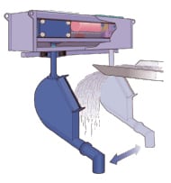
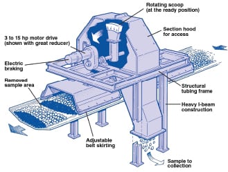
The conveyor types for mechanical and pneumatic conveying of bulk solids include belt conveyor, screw conveyor, bucket conveyor, vibrating conveyor, and dense- or dilute-phase conveyers. The best position for collecting the samples is where the material falls in a stream from the end of the conveyor. One can then follow the procedure for gravity flow or free-falling streams as noted above. However, if the situation is such that samples have to be taken directly from within the conveying line, several types of sampler have been developed. An example of such samplers designed to extract samples from belt conveyor systems is illustrated in Figure 6. The mid-belt sampler uses a rotating scoop that makes a pass across the moving belt, thereby cutting a clean cross section of material.
Slurry sampling
 |
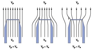 |
The same basic sampling rule where all particles have an equal chance of being sampled must also be followed when sampling from slurries. Knowledge of slurry properties and behavior is essential to insure proper sampling strategies. For instance, sampling a slurry from a point in a tank, or flowing through a pipeline requires the presence of a homogeneous suspension at the point of sampling, which is dependent on such parameters as particle size and density, fluid density and viscosity, flowrate and pipe diameter [ 4]. Turbulent flow, which provides mixing, is typically required to keep the slurry well mixed before sampling. Pipelines can be sampled isokinetically using nozzles provided the slurry is well mixed at the sampling point. Isokinetic sampling (Figure 7) occurs when the average fluid velocity in the sampling tube ( V s) is the same as the surrounding fluid velocity ( V p). No sampling bias is expected during isokinetic sampling. If the process flow velocity is greater than the sampling velocity, particle inertia causes an excess of larger particles to enter the sampling probe while a process flow velocity smaller than sampling velocity will cause an excess of larger particles to avoid the probe. Therefore, non-isokinetic sampling will introduce a bias based on the particle size distribution.
It is better to sample from a vertical pipe so that particle segregation by gravity can be avoided. In such a situation, the sampler should be located at least ten pipe diameters downstream from any bends or elbows in the pipe.
Particle diameter has a strong influence on particle segregation by gravity since the settling velocity is proportional to the square of the particle diameter. Gravity starts to play an important role at particle diameters greater than roughly 50 microns. The best approach, if possible, is to sample at the discharge where a cross-stream sampler (Figure 5) may be used as a primary sampler followed by a Vezin sampler cutter to reduce sample size. This allows sampling even in the non-ideal case where some segregation may have occurred in the pipe. A large number of cuts (>30) for both the primary and secondary samplers needs to be extracted. Not all situations are alike, and therefore, these samplers need to be installed and designed properly to fit the application.
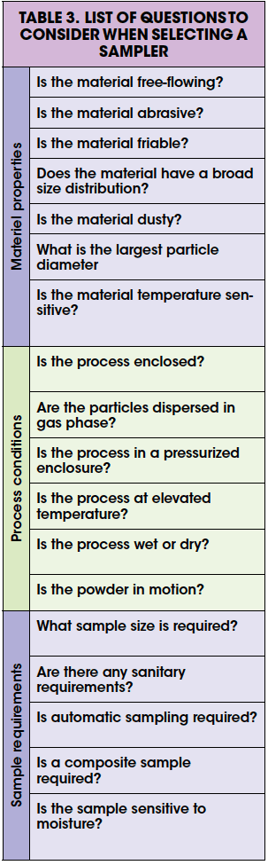
Selection of the proper sampling equipment may not always be trivial, and may depend on material properties, type of process, and sample requirements. Table 3 provides a list of questions to consider when designing a sampling protocol.
Sample reduction
 |
 |
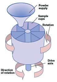
Powder sampling is typically done at two levels, a gross sample taken directly from the process, and then sub-divided into samples suitable for the laboratory. The spinning riffler, as illustrated in Figure 8, has been widely used for reducing the amount of powder to be analyzed to a smaller representative sample. In this commercially available device, a ring of containers rotates under a powder flow to be sampled, thereby cutting the powder flow into several small increments so that each container consists of a representative sample. The spinning riffler is a versatile device that can handle free-flowing powders, dusty powders and cohesive powders. The operating capacity of this device varies from 25 mL to 40 L. If only the small capacity spinning riffler is available, the Vezin sampler can be used to reduce the gross sample to the appropriate quantity suitable for the spinning riffler. The spinning riffler, when properly used, is the most efficient sample divider available.
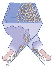
Another commonly used device for sample reduction of free-flowing powders is the chute riffler as shown in Figure 9. It consists of alternating chutes where half of the material discharges on one side and the second half on the other. The total number of chutes represents the number of increments defining the sample. Although the sample can be processed several times to increase the number of total increments, it will likely not match the number of increments performed by the spinning riffler. As such, the spinning riffler is the best device for sample reduction and should be used whenever possible.
Summary
Appropriate attention to sampling, sample size reduction and data analysis is the first step towards obtaining reliable analytical results from a batch [ 5]. To obtain a representative sample, one must adhere to the golden rules of sampling and follow the best practices as outlined in this article.
References
1. Gy, Pierre, “Sampling Theory and Sampling Practice. Heterogeneity, Sampling Correctness, and Statistical Process Control”, 2nd Ed., CRC Press, Boca Raton, 1993.
2. Pitard, Francis F., “Pierre Gy’s Sampling Theory and Sampling Practice: Heterogeneity, Sampling Correctness, and Statistical Process Control”, CRC Press, Boca Raton, 1993.
3. Allen, T., “Particle Size Measurement”, 4th Ed., Chapman & Hall, London, 1990.
4. Turian, R.M., and Yuan, T.F., Flow of Sluries in Pipepines, 3, 1977, AIChE J., Vol. 23, 3, pp. 232–243.
5. Trottier, Remi and Dhodapkar, Shrikant, and Wood, Steward, Particle Sizing Across the CPI, Chem. Eng., April 2010, pp. 59–65.
Authors

Remi Trottier is a research scientist in the Solids Processing Discipline of Engineering & Process Sciences at The Dow Chemical Co. (Phone: 979-238-2908; Email: ratrottier@dow.com). He received his Ph.D. in chemical engineering from Loughborough University of Technology, U.K,, and M.S. and B.S. degrees in Applied Physics at Laurentian University, Sudbury, Ont. He has more than 20 years of experience in particle characterization, aerosol science, air filtration and solids processing technology. He has authored some 20 papers, has been an instructor of the course on Particle Characterization at the International Powder & Bulk Solids Conference/Exhibition for the past 15 years.

Shrikant V. Dhodapkar is a fellow in the Dow Elastomers Process R&D Group at The Dow Chemical Co. (Freeport, TX 77541; Phone: 979-238-7940; Email: sdhodapkar@dow.com). He received his B.Tech. in chemical engineering from I.I.T-Delhi (India) and his M.S.Ch.E. and Ph.D. from the University of Pittsburgh. During the past 20 years, he has published numerous papers on particle technology and contributed chapters to several handbooks. He has extensive industrial experience in powder characterization, fluidization, pneumatic conveying, silo design, gas-solid separation, mixing, coating, computer modeling and the design of solids processing plants. He is a member of AIChE and past chair of the Particle Technology Forum.