This overview compares various sealing technologies, and points out advantages and disadvantages of applying different mechanical-sealing designs for caustic fluids
Caustic applications in chemical plants can play havoc on the mechanical seals of rotating equipment. These applications can be difficult to seal because of the caustic chemical properties in both solution and dehydrated states. Caustic solutions form harmful crystals as the liquid evaporates and the concentration increases past the solubility point. As the solution becomes hotter or more concentrated (or both), it becomes more corrosive, further impacting mechanical seal reliability.
Each caustic application presents unique complications due to different concentrations, desired purity levels and pump design. As a result, seal manufacturers have developed seal designs and support systems to ensure that the seal will survive the harsh demands placed on them by the pump, the process and the operating conditions. Among these new seal designs is the dynamic lift up-stream pumping (USP) technology.
Understanding these seal design options and arrangements for caustic applications, along with their benefits and shortcomings, will help chemical operations avoid costly mechanical failures, equipment damage, impacts to the environment and personnel exposure to hazardous materials.
An overview of sealing technologies
Single seals. Single seals, defined in API 682 “Pumps — Shaft Sealing Systems for Centrifugal and Rotary Pumps” as Arrangement 1 (Figure 1), are the simplest and least expensive method of achieving a seal for any pump. The mechanical seal faces are lubricated by the process fluid. In the case of applications such as caustic, normal seal leakage across the seal faces can result in plating and atmospheric side deposits that can contribute to seal component hang-up. For this reason, conventional piping plans, such as API Plan 11 are less desirable in these services.
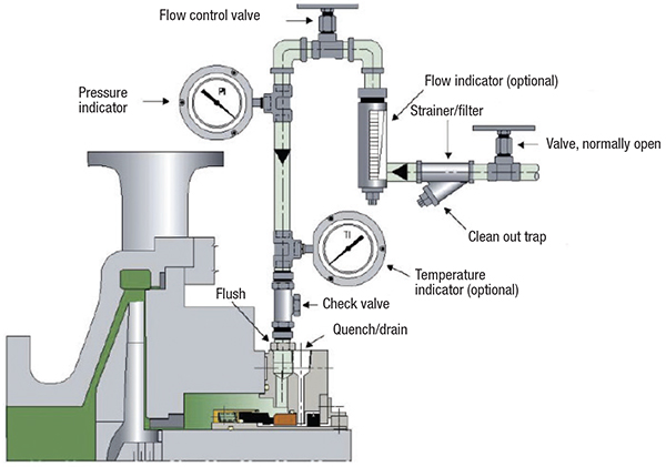
Figure 1. A typical API Flush Plan 32 is diagrammed here
For sealing caustic applications, an API 682 Plan 32 flush is often recommended. This system injects clean liquid from an external source into the seal chamber (also known as the stuffing box) at a pressure slightly higher than the chamber itself. Because the external fluid flow needs to be high enough to prevent ingress of the caustic fluid, the costs associated with the flush can prove prohibitive.
Dual unpressurized seals. Dual unpressurized seals defined in API 682 as Arrangement 2 (Figure 2), utilize an unpressurized buffer fluid between two pairs of seal faces. The inner seal faces are lubricated by the process fluid. Any leakage across the inner seal is added to the buffer fluid.
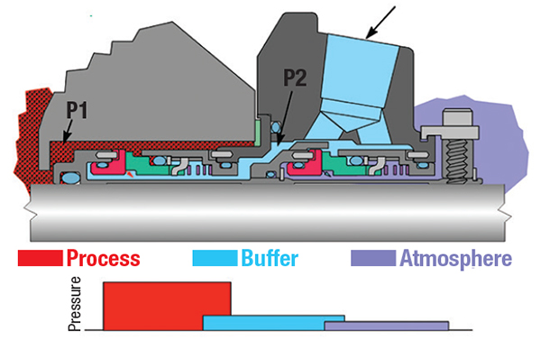
Figure 2. Shown here is a typical dual unpressurized seal pressure arrangement
In caustic applications, this arrangement leads to contamination of the buffer fluid from inner seal leakage. To combat this, an API Plan 32 is recommended for a dual unpressurized seal, with the same drawbacks as a single seal for added fluid initial expenditure, but with the additional costs of circulating another fluid and the associated support system cost, monitoring, and maintenance requirements.
Dual pressurized seals. Dual pressurized seals defined in API 682 as Arrangement 3 (Figure 3), utilize a barrier fluid pressurized above the process pressure. The seal faces are lubricated by a clean barrier fluid. Any leakage across the inner seal face will therefore be from the barrier fluid into the process fluid.
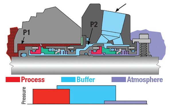
Figure 3. This diagram shows a typical dual pressurized seal arrangement
Because the leakage across the inner seal faces is clean barrier fluid, abrasive particles from the caustic fluid are isolated from the seal face area.
The initial cost of this option is the most expensive, due to the complications of providing a pressurized barrier-fluid system. However, this option generally offers better reliability than the other two arrangements since seal performance is not dependent on the process fluid for lubrication.
Dynamic-lift USP technology
A conventional mechanical seal operates by utilizing the higher pressure fluid as a film between two precision-lapped seal faces. The hydrodynamic action of the seal allows a film to form of usually less than 1µm that lubricates, cools and minimizes mechanical contact. Any leakage across the seal faces occurs from a higher pressure fluid into a lower pressure region.
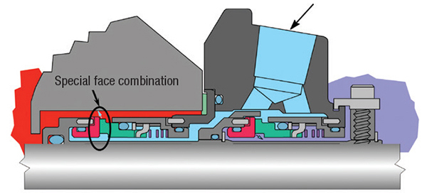
Figure 4. A typical up-stream pumping arrangement is shown here
How it works. Dynamic lift technology uses grooves on one of the seal faces to generate pressure between the seal rings so that they physically separate and operate in non-contacting mode (Figures 4 and 5). The most well-known use of this is for dry gas seals, where a barrier gas at a higher pressure than the sealed pressure is used to separate the faces.
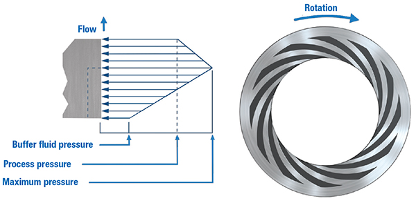
Figure 5. This diagram shows the pressure generation in a USP seal
Dynamic lift USP utilizes specially optimized spiral grooves on one of the seal faces to create a pumping effect. The face design generates a positive pressure across the seal face from inside diameter to outside diameter — that is, from the lower-pressure buffer fluid to the higher-pressure process fluid in the seal chamber. This has the effect of raising the pressure of the fluid film between the seal faces to above that of the process (Figure 5). The pumping mechanism creates a controlled flow of buffer fluid from low-pressure into the higher-pressure process fluid. The seal acts like a pressurized dual seal without the need to pressurize a barrier fluid. The low-pressure buffer fluid is sealed by a containment seal typically operating at the pre-set buffer-fluid pressure, but capable of containing the seal chamber pressure in the event of an inner seal failure.
Advantages. Dynamic-lift up-stream pumping technology offers many advantages over the traditional dual-seal approach, including the following:
- The technology is “non-contacting” and therefore the usual pressure-velocity limitations imposed by contacting seals, and the resultant wear, do not apply
- The power consumed is significantly lower than a dual-pressurized or unpressurized seal arrangement
- Compared to a dual unpressurized seal, a USP seal has the advantages of clean fluid lubrication and non-contacting operation
- Compared to a dual unpressurized seal, a USP seal requires a much simpler support system
- The process fluid is on the outside diameter of the seal faces — solids suspended in the process fluid are centrifuged away from the seal faces and secondary seal area
- Buffer fluid leakage to atmosphere is significantly reduced when compared to a pressurized dual seal, where the outer seal can often operate with a considerable pressure differential
- The concept allows a simple upgrade of single- or multiple-seal services where process changes have rendered the process fluid a poor seal lubricant
- In services where the process pressure is variable, or where pressure spikes are likely, the spiral groove constantly regulates against this varying pressure, maintaining a sealing gap at all times
- The flush requirement for dual pressurized or unpressurized arrangements is often unnecessary with USP due to low heat generation, reducing water usage
- Increased mean time between repair (MTBR)
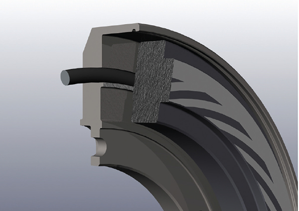
Developing the high-pressure USP seal. The first high-pressure USP seal was designed and validated back in 2003. The initial design focused on an emulsification of oil and water contaminated with varying concentrations of sand.
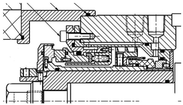
Figure 6. This cutaway shows the first high-pressure USP sealing arrangement
The 75-mm seal design shown in Figure 6 was tested under the following operating conditions:
- Shaft speed: 3,600 rpm
- Seal chamber pressure: 5 to 40 barg
- Seal chamber temperature: 70–80°C
- Process fluid: water, water/oil/sand (20 wt.% sand)
- Buffer fluid: seawater
Simplified seal-support systems. By nature of the design and operation of dynamic-lift USP mechanical seals, the required support system complexity is greatly reduced compared to that used with a conventional dual pressurized seal.
For example, due to a lack of cooling requirement for many designs, the system requirement is simply an elevated tank with an optional automatic fluid top-up system. Figures 7 and 8 show examples of a basic support system.
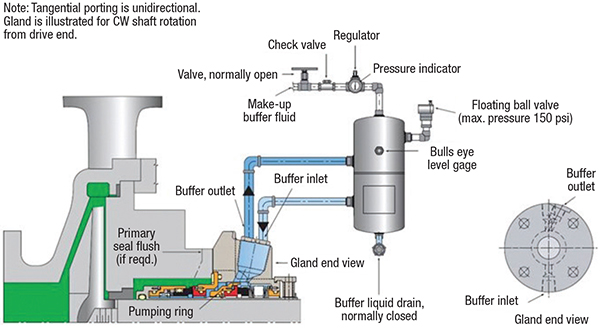
Figure 7. This schematic shows a typical piping plan arrangement
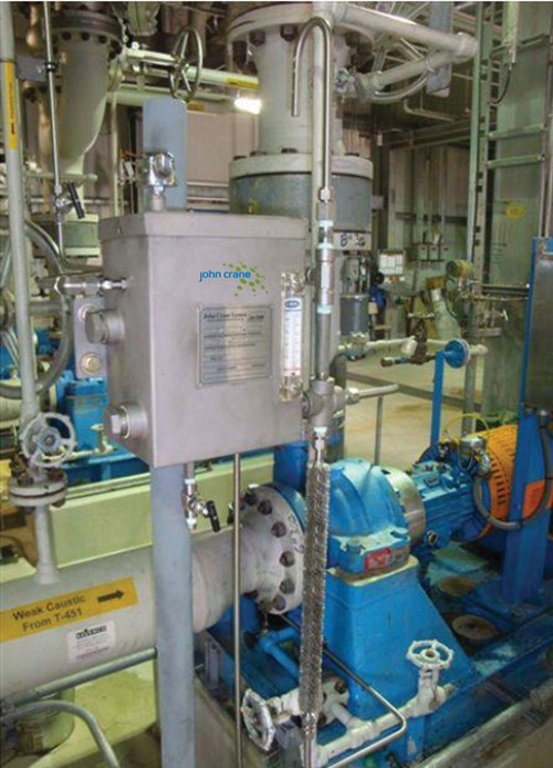
Figure 8. A typical piping plan arrangement with a USP seal in operation
Two case studies
This final section presents two applications of the mechanical seal using dynamic-lift technology.
Case 1. Improving MTBR at a chemical plant. Recently, a chemical plant in the eastern U.S. experienced a high seal-failure rate on one of its proprietary single-pump processes. Over the course of one year, the traditional mechanical seal required repair or replacement at least 17 times.
The toll plant, specializing in intermediates, polymers and colorants used by a diverse customer base around the world, relied primarily on a manual operation, leading to repeated production errors. The low seal mean time between repair (MTBR) hit the company’s bottom line in production and maintenance costs.
A thorough review of the operation and a comprehensive failure analysis revealed that employees would manually dump improper levels of crystal particles into a conical-bottom process tank. Because there was no way to measure the proper particle-to-water ratio — only employee judgment — incorrect levels were applied, often in chunks. As the volatile mixture recirculated in the tank, the seal and pump would not only starve at the start, but would also deadhead at the end of the process. This caused the seal to overheat and cook the O-rings until they resembled “charcoal.” Engineers consided a proven recirculating seal-support-system technology that would accommodate the manual process.
After the pump was rebuilt, the plant agreed to a six-month trial that replaced the existing mechanical seal with a 1.750-in. T5620 USP seal. The seal was chosen for the operation because it is designed to handle the inconsistent and caustic mixtures of the plant’s manual-dissolution process. Inboard seal faces, comprised of silicon carbide material, combined with the dynamic-lift USP face pattern.
Following the six-month trial, plant engineers said they “were ecstatic” with the performance of the T5620 USP seal. The USP seal racked up an impressive three-year MTBR, a significant improvement over the previous MTBR performance. Immediately following the installation of the USP seal, the plant eliminated the frequent half-day production interruptions, saving the company untold sales revenue. Pulling technicians away from other duties, oftentimes for four to six hours to work on the pump and seal, came to an end. The plant saved nearly $25,000 in seal-repair costs over three years after the USP was installed.
Case 2: Saving water at a chemical-processing plant. Engineers at a large chemical manufacturing plant on the east coast of the U.S. were concerned about how much water it used to process lithium hydroxide. Packing on a water pump used in the process caused significant water loss, requiring constant adjustments by plant technicians.
When the water/lithium hydroxide slurry seeped into the red clay under the plant, the reaction caused significant concrete floor heaves. The U.S. Environmental Protection Agency (EPA; www.epa.gov) required the plant to curtail the water and lithium hydroxide losses and adhere to regulations. The 24/7 chemical-manufacturing plant needed a cost-effective solution to stop the leakage to reduce costs, stop damage to the floor and conform to EPA requirements.
The company sought a solution to the problem on an open-vane, recirculating propeller pump. After careful review, it was determined that the lithium-hydroxide process was losing nearly 1.8-million gallons of water annually. Because of the water leakage, the plant’s floor would heave approximately 1.25 in./yr at the site of the process. Some areas of the floor rose 6 in. higher than other spots, creating trip hazards and costly pump, piping and infrastructure adjustments. Because of the thick and volatile nature of the slurry, traditional seals had not worked to correct the problem in the past.
Plant engineers agreed to discard the existing pump packing and replace it with engineered USP non-contacting face and filtered water-buffer-fluid seal technology. The pump was reconditioned and a 2-in. T5620 USP seal standard double-seal was installed.
The USP seal performed for six years of uninterrupted operation, eliminating constant attention from plant service personnel to service the pump packing. Annual planned packing replacement was eliminated. Excessive water consumption and associated costs were immediately halted, allowing the plant to cut water usage by up to 1.8 million gal/yr. EPA concerns regarding the water leakage into the clay soil were addressed. Leaks into the ground from the lithium-hydroxide process no longer caused the floor to heave.
Edited by Gerald Ondrey
Author
 Brian Kalfrin is a senior regional engineering manager with John Crane Inc. (4001 Fair Dr., Pasadena, TX 77507; Phone: 1-281-474-1700; Email: bkalfrin@johncrane.com), with over 19 years of experience with mechanical seals and related systems. He is responsible for engineering expertise within the North America Region for John Crane, encompassing the U.S. and Canada. His duties include design engineering oversight, analysis, and recommendation formulation to address challenging problem applications, along with design evaluation of existing and proposed mechanical seals. He is also responsible for training both customers and John Crane personnel in both mechanical seal application and troubleshooting. Kalfrin is a member of the Texas A&M International Pump Users Symposium Advisory Committee, the API 682 Task Force currently working on the 5th Edition. He holds a B.S.M.E. degree from Drexel University in Philadelphia, Pa.