Sequencing batch reactors (SBRs) are a variation on the activated sludge process in wastewater treatment. This article provides an overview of SBRs, including their history, current use and future outlook
Sequencing batch reactors (SBRs) are a type of wastewater treatment technology that are variations on the well renowned activated sludge process. Unlike the conventional activated sludge process, an SBR is a batch process that combines equalization, biological treatment and final settlement in a single tank, therefore removing the need for independent final settlement tanks and recycle streams. This article provides an overview of SBR technology and operation, and, in addition, explores characteristics of SBRs of the future.
SBR history
In the early 20th century, two engineers by the names of Edward Arden and William Lockett, under the guidance of Gilbert Fowler, developed the activated sludge process and created a legacy that changed the face of wastewater-treatment engineering and a technology that remains prevalent today. The key development of the activated sludge process involved aerating sewage and, instead of disposing of the sludge produced, retaining the sludge for mixing with a fresh batch of raw sewage. Because the retained sludge had been previously oxidized, it was considered to be “activated,” and hence was given the name “activated sludge” [1].
In more recent times, an activated sludge plant is predominantly known to be a continuous process, but in fact, the first activated sludge plants developed by Arden and Lockett operated on a fill-and-draw principle that is more akin to the SBRs that are in operation today. Therefore, one could suggest that the history of the SBR process begins as early as 1914. This fill-and-draw operating principle was short-lived, however. By 1920, most of the early activated sludge plants had been converted to continuous flow-through systems, where the activated sludge was continually separated in a downstream settlement tank, which was segregated from the main aeration tank. The transition to continuous flow-through systems was driven by shortcomings in the early fill-and-draw designs. These shortcomings included clogging of the air diffusers during sludge settlement and the need for increased operator intervention to switch valves and clean the diffusers [1].
It wasn’t until the early 1960s that the development of batch-flow wastewater treatment processes was resumed. A. Pasveer established a variable-volume oxidation ditch technology that was rather similar to the fill-and-draw activated sludge plants of the 1910s, but with a more refined operating protocol. The phases of this process were fill and aerate, fill and settle, and effluent draw. This sequence of phases is the foundation for many of the SBR operating protocols that we see today.
Following this reinvigoration of variable-volume activated sludge processes, the technology was further advanced by Robert Irvine and William Davis who, in their 1971 paper titled, “Use of sequencing batch reactors for waste treatment: CPC International, Corpus Christi, Texas” first coined the term “sequencing batch reactor” [2]. In their continued work during the 1970s, Irvine and Davis manipulated the SBR operating conditions in such a way that favored the growth of floc-forming biomass with good settleability.
By the same time, improvements had been made to aeration devices and control systems, which made the SBR more competitive with the conventional activated sludge plants of the period [3].
The developments made by Pasveer, and by Irvine and David, as well as the improvements to SBR components, formed the foundation of SBR design that would serve as the starting point for the number of variants of the SBR technology that soon followed.
SBR operation
The operating cycle of all SBR processes have, at the least, periods of the following phases:
• Fill
• Aerate
• Settle
• Decant
Additional phases that could also be implemented include anoxic mix and idle.
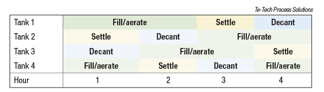
Figure 1. This figure illustrates four-hour SBR cycle timings
The phases may be overlapped or combined in several ways, and can last for different durations depending on the chosen SBR process. The overall cycle time is generally 4–6 hours and typically, multiple tanks are installed in parallel, with their phases out of sync with each other. Figures 1 and 2 show example cycle timings for a 4- and 6-hour SBR, respectively.
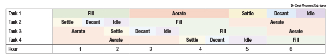
Figure 2. This figure illustrates six-hour SBR cycle timings
While the duration of each operating phase is generally fixed, there are some SBR configurations that have variable-phase durations. These SBRs will usually switch phases depending on the value given by a process monitor, as opposed to a timer. For example, an ammonia reading that reaches a sufficiently low value could be used to end the aeration phase and begin settlement.
Fill phase
During the fill phase, wastewater enters the SBR tank, generally through an open actuated isolation valve or penstock. When the tank is not in the fill phase, the inlet valve or penstock will be closed. At the start of the fill phase, the wastewater will be at the lowest water level in the tank and will continue to rise until the fill duration timer has elapsed or a particular top water level setpoint has been reached, depending on the SBR configuration.
If the fill phase has a fixed duration, then it is possible that the SBR system can be designed to have a continuous influent. This eliminates the need for an upstream buffer tank. If the fill phase has a variable duration, or there are periods in the overall SBR cycle where no tanks are receiving flow, then an upstream buffer tank is required.
Almost all of the phases listed above can be run at the same time as filling (for example, fill with aeration, fill with settling, fill with decanting and so on). However, care must be taken when operating with fill/settle or fill/decant phases because high influent flows during this period may disturb the settled sludge blanket, causing solids to enter the treated effluent. This situation should be avoided at all costs.
Aerate phase
The aerate phase follows, or occurs simultaneously with, the fill phase. During this period, air is introduced into the wastewater through an array of diffusers, providing oxygen for aerobic biological reactions, and mixing energy to ensure uniform aeration throughout the volume of the tank. The primary aerobic reaction is the biological conversion of soluble and colloidal organic compounds into water, carbon dioxide, soluble microbial byproducts and cell growth (Figure 3). This conversion is quantified in terms of biological oxygen demand (BOD) removal. Other biological reactions include the oxidation of ammonia to nitrite, and nitrite to nitrate, as well as the uptake of phosphorus within the cells of phosphorus-accumulating organisms. These can be included or excluded in the design, depending on the needs of the SBR.
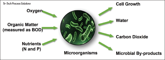
Figure 3. The inputs and outputs of the aerobic biological oxidation of organic matter are shown here
The amount of oxygen required is a function of the BOD removed, the excess mass of biomass produced, and also the mass of nitrogen oxidized, if this is required. This value is known as the actual oxygen-transfer rate. The standard oxygen-transfer rate is the amount of oxygen required for the biological reactions when accounting for several different factors, including the actual oxygen-transfer rate, oxygen-to-water transfer rate, diffuser fouling, dissolved-oxygen (DO) operating setpoint, water temperature, aeration depth and so on. From this value, the required air flowrate can be calculated.
Naturally, a number of these factors, as well as the amount of BOD removal required, varies throughout the day and year, so the air blowers should either operate in a pulse mode or allow variable speeds to avoid wasteful over-aeration of the biomass. Generally, with a variable-speed motor, the air-blower motor speed is controlled with a proportional-integral-derivative (PID) loop to meet a dissolved oxygen setpoint. Typically, the dissolved oxygen concentration setpoint is 2 mg DO/L. Some more advanced SBR systems use algorithms to determine the actual oxygen-utilization rate of the biomass to further reduce unnecessary air usage.
There are a number of different systems for introducing air into the wastewater, each with its own benefits and weaknesses. These include the following:
• Coarse bubble diffusers
• Fine bubble diffusers
• Surface aeration
• Submersible aerators
• Jet aeration
In early SBR installations, coarse bubble diffusers were common, but these are rarely used in modern designs due to their propensity to block. The blocking is caused by biomass clogging the diffuser holes during the phases with no aeration.
With an operating principle that is similar to coarse bubble diffusers, but with smaller holes, fine bubble diffusers have been used with greater success. Fine bubble diffusers are available in a few different geometries (tube, disk, plate and dome) and in a few typical materials, such as rubber, flexible plastic or ceramic. The small holes reduce the likelihood that the diffusers will block, compared to coarse bubble diffusers. In addition, the smaller holes lead to finer air bubbles and therefore, a greater overall surface area. This results in a greater oxygen-transfer efficiency.
Jet aeration works on the principle of drawing mixed liquor within the SBR tank via a pump and ejecting it with air through a jet nozzle. This method provides a high efficiency of aeration and mixing, and can easily provide anoxic mixing by switching off the air blower while keeping the mixed-liquor pump running. However, the high aeration efficiency is generally only realized when installed in deep tanks (8 m) [ 4]. This could be an issue for some SBR systems that have lower maximum tank heights due to their limited decanting depths.
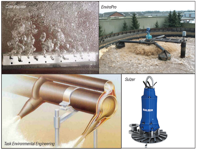
Figure 4. The photos show: a coarse bubble diffuser (upper left; Cole Parmer); surface aeration (upper right; EnviroPro); submersible aerators (lower right; Sulzer); and jet aeration (lower left; Task Environmental Engineering)
Settle phase
In the settle phase, aeration and mixing is stopped, and flocs (large clusters) of biomass that are formed in the preceding phases aggregate as a blanket and settle toward the base of the tank. In some SBR designs, the settle phase runs in parallel with a fill phase. Care must be taken when operating in this way so as to not disturb the sludge blanket so much that solids carry over into the treated effluent stream.
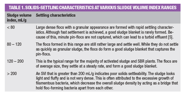
How well the solids settle in an SBR system (or an activated sludge system) is typically quantified using a parameter known as the sludge volume index (SVI). The SVI is defined as the volume in milliliters that is occupied by 1 g of activated sludge after 30 min of settling. Generally speaking, the lower the SVI value, the faster the settling. Table 1 indicates the settling characteristics at various SVI levels.
Decant phase
At the end of the settlement phase, a working SBR will have two distinct layers: the sludge blanket layer toward the base of the tank; and the clear treated effluent layer that sits above the sludge layer. In the decant phase, a portion of this treated effluent is removed from the system via a decanter. There are several decanting methods and devices available that are either off-the-shelf units or unique to specific SBR variations. In any case, the decanting device that is chosen should align with the following design considerations:
• Mixed liquor should not enter the decanter at any time during fill, aerate, anoxic mix or settlement phases
• Settled sludge should not enter the decanter during the decant phase. This may happen if the decanter is lowered too quickly or too far, both of which disturb the sludge layer
• Floating scum should not enter the decanter when decanting
• The decanting rate should be controllable, if possible, to match the varying influent conditions
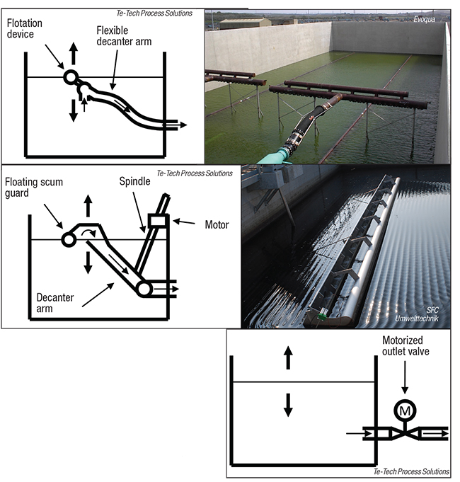
Figure 5. The figure shows diagrams and photos for different decanter types: a floating decanter (upper images; photo: Evoqua Water Technologies); motor-driven decanter (middle images; photo: SFC Umwelttechnik); and fixed-position decanter (bottom diagram)
The various designs of decanting devices can be generalized into three categories: floating, motor-driven and fixed position. Example images and diagrams can be seen in Figure 5.
Floating decanters and motor-driven decanters operate on a similar principle, in that treated effluent enters them through an orifice (or multiple orifices) that move with the water level as it decreases in the tank. Floating decanters accomplish this passively with a floatation device, while motor-driven decanters do this by actively driving the decanter arm into the water at a controlled rate. These types of decanters offer the benefit of starting the decanting from the surface of the water. This means that by the time the decanter reaches the bottom water level, extra settlement will have occurred. This reduces the risk of solids carryover.
In contrast, fixed-position decanters do not move with the water level, and instead draw treated effluent from a fixed position (or multiple positions) under the surface of the water. The ability to decant from a fixed position relies on complete settlement having occurred in the settlement phase. If solids settlement in the settlement phase is insufficient, then solids carryover could occur immediately in the decant phase. Additionally, with rudimentary fixed-position decanters, settled sludge may get sucked into the effluent pipe if the local flow velocities are too high.
However, a potential benefit of fixed-position decanters is that they offer more flexibility in tank geometry. Floating and motor-driven decanters are limited by a certain decanting depth, whereas fixed-position decanters do not have such a limitation. This means that the tanks can be tall and narrow, and therefore have a smaller footprint compared to an SBR with floating or motor-driven decanters of an equivalent capacity. Nonetheless, with a tall, thin tank, the settlement phase will need to be longer in duration than that of a shallow tank, because the sludge blanket needs to travel a greater distance in order to fall below the fixed outlet pipe.
SBRs of the future
In the U.K. around the late 1990s to early 2000s, many SBRs were installed, but a great number of these installations suffered from poor settlement caused by the excessive formation of filamentous bacteria. This, in turn, caused many consent failures when solids carried over into the treated effluent [6]. As a result, SBRs fell out of favor with many water companies, and several were even replaced with conventional activated sludge plants.
However, in more recent years, SBRs are seeing a resurgence with improved designs to combat the issues with filamentous bacteria formation. Some of the improvements include incorporating greater control over aeration rates, return activated sludge flowrates and decanting rates, and incorporating a selector zone to favor the growth of floc-forming bacteria over filamentous bacteria. SBRs are at the stage now where they can reliably deliver compliant treated effluent while minimizing the risk of solids carryover.
In the U.K. water industry, current and future drivers of wastewater treatment works are heavily based around nutrient (nitrogen and phosphorus) removal. In addition, the delivered solutions are generally required to have low energy requirements and small footprints, which is important in areas where land availability is a premium. Therefore, the future of SBRs lies in increasing the performance of nutrient removal and further driving down the footprint and energy usage.
To some degree, this is being done today already. For example, certain SBR variants incorporate biological phosphorus removal by providing the ideal conditions for the growth of phosphorus-accumulating organisms (PAOs). This, combined with high solids settlement and capture efficiency, has led to effluent total phosphorus concentrations of less than 1 mg/L without chemical dosing.
Another significant development is the optimization of process biology to select for so-called “macrofloc” formation over filamentous bacterial growth. These macroflocs consist of an external aerobic zone and an internal zone that remains anoxic even during the aeration phase, and this means that both nitrification and denitrification occur simultaneously. They also settle very rapidly, allowing a defined settlement phase using a driven decanter.
In terms of physical footprint, these SBR variants that consistently produce large flocs that settle well means that the system can operate at a higher mixed-liquor suspended solids concentration. Because of this, the volume required to achieve the desired level of biological treatment is lower, and so the plant footprint is also smaller.
Driving down energy usage is an aim for any treatment process, but for SBRs, this primarily comes in the form of reducing air usage. Instead of the standard residual dissolved-oxygen control, some modern SBRs utilize algorithms to control aeration, both in terms of intensity and duration. This effectively reduces wasteful over aeration and hence, reduces energy consumption.
The overall target of future SBR development is to increase the performance of total nitrogen and phosphorus removal, and to decrease plant footprint and energy consumption to the best possible extent.
Edited by Scott Jenkins
Author
 Ben Hazard is a process engineer at Te-Tech Process Solutions (Contech House, Unit 2 Chapel Lane, Rushington Business Park, Southampton, U.K. SO40 9AH; Phone: +44 023 8235 1600; Email: enquiries@te-tech.co.uk, www.te-tech.co.uk). Hazard graduated with a master’s degree in chemical engineering from Loughborough University and spent a year with Affinity Water before joining Trant Engineering as a process engineer, where he worked on a number of projects in water, wastewater and general processing. In 2021, Hazard moved into Trant’s newly formed subsidiary Te-Tech Process Solutions, where he specializes in the design, construction and commissioning of wastewater treatment plants.
References
1. Wilderer, P. A., Irvine, R. L. & C, G. M. “Sequencing Batch Reactor Technology,” IWA Publishing, 2001.
2. Irvine, R. and others. “Use of Sequencing Batch Reactors for Waste Treatment,” Texas., 1971.
3. U.S. Environmental Protection Agency. Wastewater Technology Fact Sheet, Sequencing Batch Reactors, Washington, D.C.: Office of Water, 1999.
4. Metcalf and Eddy, “Wastewater Engineering Treatment and Resource Recovery.” 5th ed., New York, McGraw-Hill, 2014.
5. Trygar, R., 2015. TPOMAG – Back To Basics: What Is The Settleability Test?. [Online] Available at: www.tpomag.com/editorial/2015/05/back_to_basics_what_is_the_settleability_test [Accessed July 2021].
6. Smyth, M. and Horan, N., Sequencing Batch Reactors: Past, Present and Future, paper from the 8th European Water Management Conference,, 2014.
Additional resources
Cole Parmer, Plenum Coarse Bubble Diffuser. [Online] Available at: www.coleparmer.co.uk/i/plenum-coarse-bubble-diffuser-304-ss-1-ft-l/7002510 [Accessed 02 08 2021].
EnviroPro, O2 Max surface aerators. [Online] Available at: www.enviropro.co.uk/entry/39029/Spaans-Babcock/O2-Max-surface-aerators/ [Accessed 02 08 2021].
Sulzer, Submersible aerators [Online] Available at: www.sulzer.com/en/shared/products/submersible-aerator-type-abs-xta-xtak [Accessed 02 08 2021].
Task Environmental Engineering, Jet aeration systems – high performance aeration system for wastewater treatment plants. [Online] Available at: task.be/en/jet-aeration-systems/ [Accessed 02 08 2021].
Evoqua Water Technologies, Floating decanter. [Online] Available at: www.evoqua.com/en/evoqua/products–services/aerobic-wastewater-treatment/aerobic-systems/solids-excluding-decanters/ [Accessed 02 08 2021].
SFC Umwelttechnik, Motor-driven decanter [Online] Available at: sfcu.at/ [Accessed 02 08 2021].