Flow analysis can aid in simultaneously sizing pumps and associated piping systems. The concurrent sizing can reduce wasted energy and improve pump reliability
In the chemical process industries (CPI), a variety of incredible process-simulation tools are available to provide greater efficiency and understanding to numerous chemical processes. Key process-stream parameters include flowrate, pressure, temperature and process media composition. From these inputs, an entire operation can be modeled. However, these important process inputs can be easily taken for granted.
Piping networks are the lifeline to plant process units. Their operation is just as critical as the process units themselves to ensure that the required flows, pressures, temperatures and compositions are delivered. Pumps, piping systems, and other components must be sized and selected properly. Like process simulation, flow-analysis software can greatly aid the pump- and pipe-sizing process.
There is a vast amount of literature available that discusses the procedure for sizing a pump [ 1]. The procedure is simple for systems that involve one, two, or maybe three flow paths, and many engineers share the experience of running through these calculations at one point or another. However, when dealing with much more complicated systems that involve several flow splits, loops, control features, multiple pumps in parallel, and so on, it is not an easy task. This is where flow-analysis software offers great utility — not only to size the pump itself, but to also to provide much more insight into system operation, where you can model different scenarios, as well as system operation and configuration changes.
Ref. 2 discusses how to improve pump system reliability through determining how to operate pumps closer to their best efficiency point (BEP). The focus of that article was on existing piping systems to improve system reliability.
This article examines the benefits of concurrently sizing the pumps and piping system together, instead of sizing pumps and piping individually. Sizing the piping system with the pumps will allow the selected pumps to fit the system application better, and thus prevent dramatically oversized pumps. When pump oversizing occurs, it is typically dealt with by using throttling valves, an approach that not only wastes a significant amount of energy (leading to high electricity costs), but also diminishes pump reliability. Sizing the pipes and pump together establishes a functional design that also saves a significant amount of money by finding a lower-cost solution for the system. This is especially true when sizing the system with consideration of the overall lifecycle cost.
Sizing example
Consider the system shown in Figure 1, where the pumps, piping, fittings and control valves need to be sized. For this system, there are four requirements that will dictate the piping size design. Fluid velocities inside the pipes must be below a certain threshold. There is a minimum pressure throughout the network that must be maintained. The coolers require a minimum flowrate for proper cooling. The pumps need to have plenty of margin between the net positive suction head available (NPSHA) for the pumps and the net positive suction head required (NPSHR) by the pumps.
To size the pumps, a desired flowrate will typically be specified in the model and the increase in pump head (or pressure) that is required to deliver the flow to overcome system resistance and elevation change will be determined. That establishes the pump operating point, which can be used to select a pump.
At the same time, different pipe sizes throughout the system will be used to meet the design requirements. If any of the design requirements are not met, then those sizes would not yield a feasible design. As the pipe sizes change, the pump requirements for the desired flow will also continually change. Therefore, this is a highly iterative process.
Simply meeting the design requirements is not the only thing that should be considered in establishing a “good design.” How can engineers know if it is good, or if the design could be better, or if it is the best possible design available? To answer this question, cost must be considered. Monetary cost for the system is certainly helpful in establishing a high-quality design. But at the very beginning of the design process, detailed costs may not yet be known. At that point, the overall piping weight can be a good initial start at the design.
Reducing piping weight typically corresponds well with reducing the initial material and installation costs for the system. Designing the pipe sizes with a maximum velocity requirement in mind can also help reduce energy costs in the long run.
Overall, the best design in theory would be the one with the lowest cost or lowest piping weight. It is worth noting that even when sizing the system based upon monetary costs, it is not necessary to have incredibly accurate cost data. Simple estimates, such as cost per length of piping or cost per power unit for pumps, is sufficient. Even if these costs are referenced from another project, industrial cost tables, old cost data, or even a guess, the “absolute” value of the cost is not what is important. What is important is the cost savings that is generated during the process of the system sizing.
Flow analysis
For the system being sized in Figure 1, the goal is to minimize cost for the appropriate sizes that will work. There are two different cost considerations to minimize: either the initial cost of the system or the lifecycle cost of the system. If we try to minimize the initial cost of the system, then smaller pipe diameters might be used, which would require larger pumps and higher power usage. In the long term, this will lead to higher energy costs. When attempting to minimize the overall lifecycle cost, then larger pipe diameters might be used to allow smaller pumps with lower power requirements from smaller pressure losses. This would lead to higher initial costs, but can save a sizable amount of money in the long run.
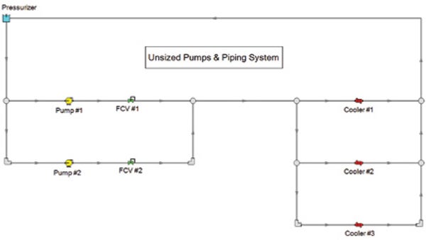
FIGURE 1. In the initial piping system layout shown here, pipe sizes and pump operating points have not yet been determined
During the sizing process, many pipe size combinations will be used to try to meet requirements and decrease costs. Carrying this out manually is very difficult, but flow-analysis software with automated pipe-network sizing capabilities dramatically streamlines the process.
Imagine a situation where you were given ten different pipe-network size configuration options. You might start by trying a couple of the design options to see if they meet the design requirements. If one option did meet the requirements, how many more design options would you analyze to try to further minimize the costs? Most likely, many would be hard-pressed to analyze all ten options to find which one gave the lowest cost.
The reality is, there are not just ten different design options that exist, but potentially millions and billions. Flow-analysis software tools have sophisticated mathematical algorithms to quickly analyze a large number of different options. Engineers will have much greater ability to further investigate multiple options, leading to pathways that dramatically reduce costs while still meeting requirements.
In the simple system from Figure 1, there are a total of 21 pipes in the model. Pipe size is the independent variable that is being changed during the automated sizing process. Without grouping pipes together, there would be 21 independent variables and hence, there potential exists for 21 different pipe sizes. Since this number is not very practical, grouping various pipes together will help reduce the number of variables. This situation illustrates how there really are many different sizing combinations that can exist for a given pump-system design.
Cost comparison
After assuming basic material, installation and energy costs for the system, the model will result in two different pipe size designs. In one design, the goal is to minimize the initial cost for the system. Since energy costs can still easily be calculated, that information will be included for comparison. But this design will not consider energy costs for the sizing process. For the other design, minimizing the overall lifecycle cost (which does consider energy costs) will be analyzed.
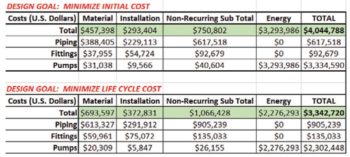
TABLE 1. The costs of the sized piping system according to the different design goals are compared here
Table 1 provides a comparison for the cost results for the sized piping system. The option to minimize the initial cost results in a total initial cost of $750,802. As seen in Figure 2, smaller pipe sizes are needed to meet the design requirements. However, calculating the energy costs of about $3.3 million will lead to a larger total lifecycle cost of just under $4.1 million over 20 years.
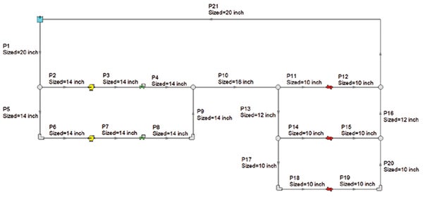
FIGURE 2. The pipe system shown here results when the design goal is minimizing initial system costs for material and installation
Considering pipe-size designs with the primary goal of minimizing the overall lifecycle cost will have a dramatic impact on long-term energy costs. This is because larger pipe sizes will be used and that reduces system pressure drop as well as pump-power requirements. Although the system shown in Figure 3 for the design goal of minimizing lifecycle costs results in about 42% higher initial costs, savings of 17% in total cost is realized in the long run. Notice that the energy costs for the case of minimizing lifecycle cost is about 31% lower than simply minimizing initial cost.
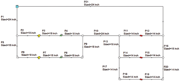
FIGURE 3. When the design goal is to minimize the lifecycle cost of the pipe system, the diagram here is the result. About 17% in cost savings can be realized compared to minimizing initial costs
Lastly, now that the piping has been sized, the pump operating points are simultaneously determined. This allows the selection of pumps that will be a much better fit for the system demands, since the pump will not be unnecessarily oversized. They can also be selected to operate at close to their BEPs (or as close as possible) at the pump operating points.
Simultaneous pump- and pipe-system sizing will help establish a design that will meet the required flow, pressure, temperature and composition demands needed for various process operation. This allows engineers to have much greater certainty behind input values for their process simulation — now they are known instead of only being assumed. And if the pump-and-piping system is designed with the goal of minimizing overall lifecycle cost, this will have a dramatic impact in the long term. The approach will realize great monetary savings with reduced energy costs when compared to the approach of simply minimizing the initial cost of the system. Flow analysis can be accomplished with great efficiency using flow-analysis software with automated pipe-network sizing capabilities.
Edited by Scott Jenkins
References:
1. Kelly, M., “Pump Sizing 101,” Pumps & Systems Magazine, May 28, 2021, www.pumpsandsystems.com/pump-sizing-101.
2. Keiser, B., A System Approach with Flow Analysis,, Chem. Eng., October 2021, pp. 34–38.
Author
 Ben Keiser is technical sales manager for Applied Flow Technology (AFT; 2955 Professional Place, Suite 301 Colorado Springs, CO 80904; Phone: 719-686-1000; Email: info@aft.com; Website: www.aft.com), a leading dynamic fluid-flow analysis and waterhammer mitigation software company. Keiser helps engineers understand how to design safe and efficient piping and ducting systems. His passion and expertise can be accessed around the world as he trains engineering teams how to efficiently perform flow-analysis simulations to find optimized solutions. Prior to joining AFT, he worked for Eaton Corp. and WellbornYX Corp. Keiser holds a B.S.Ch.E. degree from the Colorado School of Mines.