Various heating or cooling options are described here, along with the factors and design parameters that need to be considered. A sample calculation regarding coils is included
Tanks constitute important equipment in the chemical process industries (CPI). Various types of liquids are stored in tanks and often these liquids are difficult to handle due to their high viscosities. Generally, increasing the temperature lowers the viscosity, resulting in ease of pumping. Therefore, temperatures inside tanks sometimes need to be maintained at elevated levels. In some cases, low temperatures must be maintained in order to avoid polymerization, undesired reactions or product degradation. In a nutshell, temperature control inside tanks may be required.
Designing a tank heating or cooling system involves two basic steps. The first step is to determine the heat loss from the tank to the surroundings (for hot liquids) or the heat gain by the tank (for cold liquids). The second is to design the system to compensate for the heat loss or gain. The purpose of this article is to provide an overview of the design procedure for tank heating and cooling systems for any given service to achieve the previously described objectives.
Types of heating and cooling systems
Tank heating or cooling systems can be implemented in a number of ways. The various options include direct steam injection or indirect heating. Indirect heating includes the following:
- Steam tracing
- Heating or cooling with internal coils
- Steam jacketing
- Electrical heating
- External heating or cooling by liquid circulation
- External cooling by vapor recompression
The above options have distinct differences and some even have limitations that make them suitable for certain applications, but unsuitable for others. A combination of the above methodologies is also possible. For example, steam heating coils and wall steam tracing often come in pairs.
Direct steam injection.Direct steam injection [1] is the simplest method and can be a very efficient way for heat transfer since both the latent heat and the sensible heat are used for heating (Figure 1). It is appropriate only when dilution or an increase in liquid mass is acceptable and the process fluid is not sensitive to steam injection. Direct steam injection is the most widely used method for boiler-feed-tank heating. Various types of tank spargers are available for this purpose. However, in such cases, because the steam mixes with the process fluid, steam hammer and vibrations often occur, leading to higher maintenance costs.
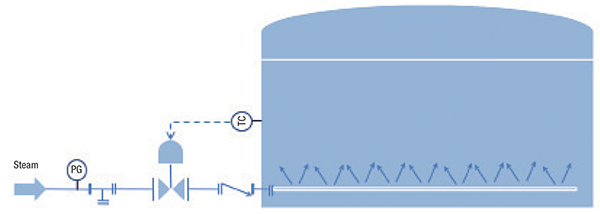
Figure 1. Direct steam injection is the simplest method for heating. Shown here is steam injected through a sparger in an open tank
Steam tracing. To provide a good heat distribution over the surface of the tank, steam tracing is carried out with 3/8- or 3/4-in. tubes that are made of copper or aluminum. Direct contact with the tank wall produces good heat transfer, but it is difficult to predict the performance since it is strongly dependent on the degree of contact. The tubes are wrapped around the tank manually, and hence the degree of contact with the tank wall is not very effective. As a result, the overall heat-transfer coefficients exhibited by steam tracing could be as low as 5–6 W/m2.°C. The use of heat-transfer cement improves the performance, however with an added cost. As a rough estimate, the installed cost of tracer with cement is approximately double that of tracer alone.
Heating with internal coils. With internal coils, both the compensation for heat loss or gain and additional heat duty required for intermittent services (such as startup heating after a prolonged shutdown) are possible to meet. Coils placed at the bottom of the tank mainly target bulk heating. Coil assemblies placed close to the walls at different heights compensate heat loss through the insulated cylindrical wall. If the temperature of the fluid entering the tank varies, then agitation is needed to create a buffering effect and to limit temperature fluctuations within the tank.
As a heating medium, normally low-pressure steam is recommended, since high temperatures in the coils could cause severe corrosion. Such heating or cooling systems could be designed for a wide range of heating loads, a feature not associated with the other tank heating options.
Steam jacketing. Jacketing is often used for tanks needing frequent cleaning and for glass-lined vessels that are difficult to be equipped with internal coils. A storage tank for liquid sulfur is a typical application that involves jacketing. The heat-transfer coefficients on the steam side are normally high. The process side heat-transfer coefficient can be increased by agitation [2]. In terms of thermal efficiency, steam jacketing lies in between the submerged coil and steam tracing.
Electrical heating. The design of electrical heating systems is vendor specific. A typical application is the compressor lube-oil reservoir-heating system, which is applicable in cold locations. The low ambient temperatures in these areas cause a rise in the viscosity of the liquid as a result of natural cooling during long shutdowns, which renders pumping of the fluid very difficult.
External heating by liquid circulation. There are instances where leaks may develop from corrosion of coils due to scaling by high concentration inside the tank. In such cases, internal heating coils are not recommended [6], and heating or cooling through external exchangers could be used (Figure 2). A pumping arrangement with an external heater or cooler facilitates good mixing in the tank with the help of an eductor, thus promoting forced circulation. The heat generated by the circulating pump sometimes also adds to the heat input. However, for a cooling systems, this could be counterproductive.
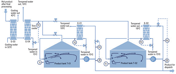
Figure 2. This diagram shows an external cooling arrangement for a pair of storage tanks
External cooling by vapor recompression. Vapor recompression with an external heat exchanger is often used for refrigerated and semi-refrigerated liquids like ammonia, propylene, propane and so on. In such systems, the heat gain from the tank wall results in the generation of boil-off vapors (Figure 3). These boil-off vapors are recompressed, cooled to liquefy the vapors, and returned to the storage tank.
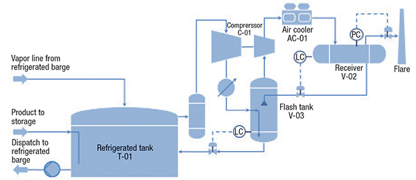
Figure 3. A typical vapor recompression system is shown here
Various design conderations
The system should be configured suitably, depending upon the goal. There is no general rule and every scheme must be carefully considered based on the availability of the heating or cooling medium. Factors like utility requirements, size of the hardware (heat exchangers, pumps and compressors), heat loss and so on are to be judged carefully along with the associated process systems.
Consider the example given in Figure 2. In this figure, the hot product from the upstream processing unit at a temperature of 50°C is required to be stored at a temperature between 18 and 22°C in two product storage tanks. A target operating temperature of 20°C is selected to be maintained inside the tanks T-01 and T-02. The product is cooled to 20°C in the two successive plate heat exchangers before sending it to the tanks T-01 and T-02. The exchanger E-03 uses cooling water (operating range 33–43°C) and E-04 uses tempered water (operating range 15–18°C). The minimum ambient temperature is 22°C (a typical equatorial site).
During normal operation, one tank is under the filling mode, while the other tank would be in emptying mode. The trim cooler E-04 is provided upstream of the tank and uses tempered water to cool it to 20°C. However, the tanks would gain heat from the ambient air, leading to a rise in temperature. Therefore, the tanks need to be equipped with exchangers E-01 and E-02 for external cooling and need to be operated continuously to maintain the target temperature of 20°C.
With regard to energy savings, the following case is interesting. Assume that the tank T-02 is under emptying. This means that the tank is not lined up with the exchangers E-03 and E-04 and therefore it is continuously receiving heat from the surroundings. Hence, exchanger E-02 needs to be kept under operation to remove the heat gained.
However, the tank T-01 is under filling and hence is lined up with the exchangers E-03 and E-04. Now, for the same fluid medium, the log-mean-temperature differences available in the heat exchangers E-01 and E-02 are lower than that available in the trim cooler E-04. If we can add a little extra surface area to E-04 to cool the incoming liquid to tank T-01 up to the temperature level of 18°C instead of 20°C, then the operation of the external cooling heat exchanger E-01 can be switched off and normal operating cost can be saved. Design of a similar type of intermediate storage tank heating or cooling system is explained by Catani [3].
In some services, the possible maximum temperature of the heating medium does not have any adverse affect on the contents of the tank. In such cases, a precise control of the flow of this heating medium may not be necessary or economical. For instance, if the heating medium is steam, a steam trap alone can serve the purpose.
The tank may have total or partial insulation. The presence of insulation, ambient temperature and the holding temperature affects the heat loss to the ambient air. Again, the tank surface in contact with the liquid phase has higher heat loss than that in contact with the vapor phase. Therefore, holding temperatures below 75–80°C, insulating the roof of the cone-roofed tank is not justified economically, since at such temperatures, there is very little heat loss from the vapor phase. Insulating the roof of a floating-roof tank is not usually done because of the difficulty in preventing water ponding and leakage into the insulation. The requirement of insulation is decided based on the heating or cooling arrangement. Keeping the operating philosophy and all the process constraints in mind, proper selection of the heating or cooling scheme is important before proceeding with the design.
Coils made of pipes of 2- and 2.5-in. diameter are commonly used for shop-fabricated tanks. On the other hand, those made of 1.5- and 2-in. diameter pipes are more commonly seen in field-fabricated tanks. In addition, other factors, such as the tube-side heat-transfer coefficient, higher pressure rating or layout problems also require the use of smaller diameter pipes. Closer spacing is not used for coils made of larger diameter pipes. In addition, closer spacing is not encouraged when the temperature difference between the tank fluid and the coil fluid is large.
For underground applications (like a liquid-sulfur pit), the steam-side entry and the condensate-side exit are located above ground while the coil itself is located below the ground. Such configurations, however, run the risk of condensate logging, waterhammer, noise and leaking pipe work, and therefore should only be used in such special cases.
Fins on the steam coil are not suitable if there is a possibility of scale formation. The condensate must be removed as soon as it is formed to keep the heating surface effective. Poor quality of steam, improper slope, longer coils and poor condensate drainage often lead to the problems of condensate hammering. For small tanks, this can be detrimental since the contents are not enough to create a buffering effect. External factors, such as condensate collection and steam trap arrangement, become important.
Designing the system
Inputs. Typically, the input requirements for the design of heating or cooling systems are listed below:
- Construction details of the tank, such as tank diameter, wall thickness, material of construction, insulation and so on
- Temperature of incoming fluid
- Holding temperature
- Ambient temperature (minimum and maximum values)
- Wind velocity
- Soil temperature (for heat loss calculations)
- Temperature and pressure level of the heating or cooling medium
- Whether the operation of the tank is continuous or intermittent, that is, whether the tank heating is intended to maintain a particular temperature, or only used during startup/shutdown mode at different seasons
- The properties of the tank content, for instance, fouling factor and so on
- Availability of utilities, such as cooling water, tempered water, steam, hot oil and so on
Estimating the duty. In a heating system, the design heat load is arrived at by considering the minimum ambient temperature, resulting in a conservative estimate of the requirement of utilities, such as steam. Many references are available for calculating the tank heating or cooling loads [4, 5]. The requirement of surface area of the heating coils should be considered assuming the lowest operating steam temperature. If the tank is provided with an agitator to facilitate uniform mixing, then the case of failure of agitation should also be considered while estimating the surface area.
Factors, such as heat added by agitators and through external pumping systems, heat losses through the auxiliary systems of the tank (like external cooling or heating pipe network, vapor equalization line, vapor recompression system), should be carefully evaluated to optimize the tank heating or cooling requirements.
Apart from the heat losses or gains from the surroundings (including the soil), the total heating or cooling load must consider the requirements, if any, of the temperature rise of the incoming fluid and the tank material to the desired holding temperature of the tank.
Calculation procedure for heating coils. The following description illustrates a step-by-step calculation procedure for heating coils using steam.
Step 1. Determine the heating (or cooling) duty to be served by the coil.
Step 2. Determine the overall heat-transfer coefficient between the medium inside the coil (in this case steam) and the bulk fluid. Typical overall heat-transfer coefficient values can be taken from Table 1 [7]. Otherwise, the values can be calculated empirically from Nusselt’s correlations for specific systems [4]. Such heat-transfer coefficients are experimentally derived. The coefficients could also be cross-checked using commercially available heat-exchanger design software.

In addition, application of agitation (in situ heating) or an eductor system (Figure 2) with external pumped recirculation allows further improvement in the rate of heat transfer.
Step 3. Determine the temperature difference between the steam and the process fluid.
Step 4. Determine the heat transfer area required.
Step 5. Select the diameter and determine the length of the pipe that forms the coil. Because of the difficulties in providing accurate values of the overall heat-transfer coefficient and the non-availability of effective heat-transfer surface area due to condensate flow, it is typical to add a margin to the above calculated heat-transfer area.
Step 6. The maximum recommended steam velocities passing through the heating coils are in the range of 20–25 m/s. For higher steam loads and heat-transfer areas, the steam path could be divided into several parallel paths to reduce the steam-side velocity and temperature variation. In very long coils, a significant pressure drop occurs along the length of the coil. In such cases, the coil temperature used in the calculation should be carefully evaluated. However, in any case, the temperatures should not exceed the levels that affect the thermal stability of the stored material.
Step 7. Determine the number of layers of coil required. Refer to Table 2, which could serve as a guide. The diameter of the pipe that forms the coil should be selected to provide sufficient length of the coil for uniform heat distribution. Depending upon the application and shape of the vessel, several configurations are possible. Some of the configurations are illustrated in Figure 4,.

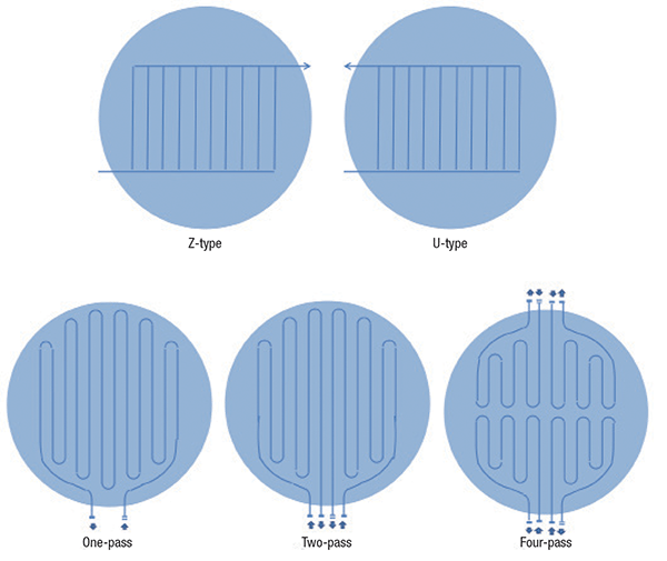
Figure 4. Coil arrangements can be Z-type (top left) or U-type (top right). The coils can be arranged to be one-, two- or four-pass (bottom, left to right)
Step 8. Depending upon the number of parallel paths, the number of inlet and outlet nozzles for the fluid in the coil is decided. Larger diameter tanks are generally equipped with a higher number of parallel paths for better distribution (one pass, two pass, four pass from left-to-right in the bottom of Figure 4).
Sample calculation for coils
Let’s consider an intermediate product (a type of vegetable oil) storage tank that has a continuous inflow rate of 8 m3/h at 80°C. At the same time, the liquid outflow rate from the tank is 8 m3/h and the downstream needs to be fed at 85°C. The properties of intermediate product are:
- Specific heat: 0.431 kcal/kg°C
- Density: 870 kg/m3
The compensation for the heat loss from the tank to the environment, as well as the heating of the tank contents, can be achieved by a suitable design of the steam coils inside the tank. The governing case for coil design will be as follows:
- Tank inventory is full (that is, the maximum rate of heat loss)
- Ambient is at minimum temperature (that is, the maximum rate of heat loss)
- The process is continuous (that is, both the inflow and outflow are at steady state)
Let’s consider the following:
- Diameter of the tank = 12 m
- Heat loss from the tank = 95,000 kcal/h (this includes heat loss to the atmosphere, heat loss to the soil and so on. Detailed calculations are not being provided to keep the example simple).
The energy required to raise the temperature of the incoming fluid from 80°C to 85°C = 8 m3/h × 870 kg/m3 × 0.431 kcal/kg°C × (85 – 80)°C = 15,000 kCal/h.
Therefore, total heat load of the coil = 15,000 + 95,000 kcal/h = 110,000 kcal/h.
Refering to Table 1 [7], the minimum heat-transfer coefficient for a non-agitated system of vegetable oil with steam is 112 kcal/h.m2.°C.
Assume saturated steam is available at 4 bars(a) (temperature of 143.63°C).
Latent heat of condensation of saturated steam at 4 bars(a) = 509.5 kcal/kg
Therefore, the steam consumption rate (normal value) = 110,000/509.5 = 215.9 kg/h
Temperature difference between the coil inside fluid and outside fluid = (143.63 – 85)°C = 58.63°C.
Coil surface area required = 110,000 kcal/h/(58.63°C × 112 kcal/h . m2.°C) = 16.75 m2.
With a coil formed by a pipe of 25-mm nominal diameter (outside diameter of 33.4 mm), the surface area for a 1-m long coil works out to 3.142 × 0.0334 m × 1 m = 0.106 m2/m.
Therefore, length of the coil required = 16.75/0.106 m = 160 m (approximately).
With a tank diameter of 12 m, from Table 2, one layer of coil can accommodate a coil length of 12 × 10.5 m = 126 m.
This is lower than the required 160-m length as calculated above. This means two layers of coil need to be considered.
Two layers of coil will have a surface area of 126 m × 2 layers ×0.106 m2/m = 27 m2 (approximately).
Maximum duty of the coil = 27 m2 × 58.85°C × 112 kcal/h . m 2.°C = 177,960 kcal/h.
Maximum steam consumption in the coil = 177,960 kcal/h/509.5 kcal/kg = 350 kg/h.
Maximum load of steam to each layer of coil = 350/2 kg/h = 175 kg/h.
Having selected two layers of coils, let us now come to the selection of the number of coil passes in each layer. If one pass arrangement in each coil layer was used, then the maximum velocity of steam in 25 mm coil works out to 46 m/s, which is rather high. Therefore we should have two layers of coils, each having two passes (as in Figure 4, bottom).
Concluding remarks
This article emphasizes the need for heating or cooling in storage tanks. For certain highly viscous liquids, temperatures inside some tanks sometimes need to be maintained at elevated levels for ease of pumping, while in some cases, lower temperatures are required to avoid polymerization, exothermic reactions or product degradations.
The various options available for heating or cooling have been described. The factors to be considered while selecting the right option are also described. The various design parameters to be considered during design are explained. A sample calculation is also illustrated. The finer aspects of coil design and engineering are also presented.
Note: The content of the article is based on the authors’ personal views and their own published research.
Edited by Gerald Ondrey
References
1. Schroyer, J. A., Understand the Basics of Steam Injection Heating, Chem. Eng. Prog., May, 1997, pp. 52–55.
2. Dream R. F., Heat Transfer in Agitated Jacketed Vessels, Chem. Eng., January, 1999, pp. 95–96.
3. Catani S. J., Control System Cuts Tanks Heating and Cooling Costs, Chem. Eng., August 24, 1981, pp. 129.
4. Kumana J. D. and others, Predict Storage Tank Heat Transfer Precisely, Chem. Eng. March 22, 1982, pp. 127–132.
6. Cowan C. T., Choosing Materials of Construction for Plate Heat Exchangers – Part II, Chem. Eng., July 7, 1975, pp. 102–104.
7. Green, D. W., Perry, R. H., “Perry’s Chemical Engineer’s Handbook,” 7th Edition, Chapter 11, Page 21, McGraw-Hill, New York, 2004.
Authors
 Apurba Lal Das is a senior principal engineer at Air Liquide Global E&C Solutions India Pvt. Ltd. (A24/10, Mohan Cooperative Industrial Estate, Mathura Road, New Delhi 110044, India, Phone: +91-11-42595365, Email: apurbalal.das@airliquide.com). He joined Air Liquide in September 2007, and has 12 years of experience in process engineering, with exposure to various technologies, such as petroleum refineries, petrochemicals, sulfur-recovery gas cleaning and more. He also has experience in plant operations. Das earned his B.Tech degree from Haldia Institute of Technology and M.Tech from I.I.T. Kanpur. He has life membership to the Indian Institute of Chemical Engineers.
 Siddhartha Mukherjee is the director – Technology at Air Liquide Global E&C Solutions India Pvt. Ltd. (same address as above; Phone:+91-11-42595365, Email: siddhartha.mukherjee@airliquide.com). He joined Air Liquide in June 1993, and has 27 years experience in the design, engineering, precommissioning and commissioning of refineries and petrochemicals plants and general process engineering. Prior to this, Mukherjee worked as an environmental engineer with Development Consultants Ltd. (Kolkata), doing various environmental impact assessment projects involving thermal power plants. he earned his B.Tech and Ph.D. Ch.E. degrees from I.I.T. Kharagpur. He has life memberships to the Institute of Engineers and the Indian Institute of Chemical Engineers. He has a number of publications in national and international journals. He is listed in the Marquis Who’s Who in Science and Engineering. He is also an Air Liquide Group International Expert.