Wet Surface Air Coolers For Cryogenic Systems
FREE | November 16, 2022
REGISTERBy condensing at lower temperatures, the Wet Surface Air Cooler allows for increased condensing capacity when compared to dry coolers. When comparing to traditional evaporative cooling techniques, such as cooling towers and heat exchangers, the wet surface air cooler can save water as well. Traditional clean water sources are not required so alternative makeup streams allow even further savings.
Applications such as LNG, cryogenic distillation/separation and other industrial refrigeration processes can reduce operating costs and carbon footprint through the use of direct latent heat rejection via Wet Surface Air Cooling. The evaporative condensing process reduces the amount of air required for cooling and thus lowers motor power consumption as well.

Facts At Your Fingertips: Physical Gas-Separation Methods
Industrial gases are critical for a wide range of applications throughout the chemical process industries (CPI). Many of these gases must be separated from others, such as nitrogen from air, or hydrogen from natural gas using physical gas-separation techniques that include membrane separation, catalytic and adsorption processes, cryogenic distillation, and other technologies. A few common methods are discussed here.
Membrane separation
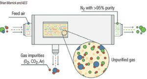
Membrane separation uses hollow-fiber membranes to separate nitrogen from oxygen (Figure 1). Membrane technology is commonly used when purity requirements are not stringent. Within the membrane system, many thousands of hollow fibers are placed in a housing and compressed air is supplied to one end. The fiber wall is permeable to gases, but the diffusion rate across the fiber wall varies according to the type of gas. For air, oxygen, carbon dioxide, argon and other trace contaminants pass through the wall at a faster rate than nitrogen, and are vented. Nitrogen exits the membrane system at a typical purity of greater than 95%. Users can adjust the flow through the system to vary the purity achieved by a membrane-based system. The advantage of a membrane-based system is there are no moving parts, but outlet purity may vary with flowrate.
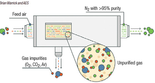
FIGURE 1. Membrane separation methods are used in applications where purity requirements are not especially stringent
Pressure-swing adsorption
Pressure-swing adsorption (PSA) and vacuum pressure-swing adsorption (VPSA) are used in situations requiring higher purity. When separation of impurities in the high parts-per-million (ppm) level is required, as opposed to separation of impurities at the percentage level, PSA is an option (Figure 2). PSA systems are typically used as pre-purification of gases entering a cryogenic process and for the purification of hydrogen. VPSA technology is used for on-site float-glass production and medical-grade oxygen.
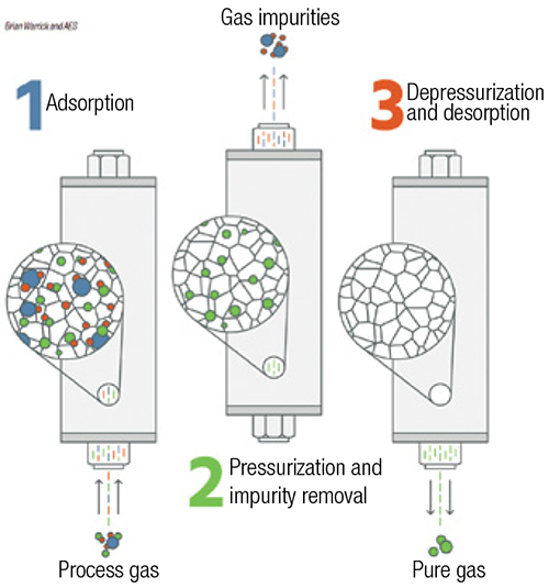
FIGURE 2. Pressure-swing adsorption is an option when the separation of impurities needs to reach the high parts-per-million level
PSA systems consist of pairs of vessels operating in parallel, or they can be designed in configurations with multiple vessels in series. Each vessel is packed with adsorption media, such as carbon molecular sieves, zeolites and charcoal. Feed gas to be purified passes through one or more vessels operating at pressures typically greater than 100 psig. Impurities within the feed-gas stream are physically adsorbed (physisorption) onto the surface of the media by Van der Waals forces (weak bonds created by short-range electrostatic interactions among molecular dipoles). PSA systems work by taking advantage of differing adsorption behavior at different pressures and temperatures. Adsorption sites are occupied by impurity molecules, while the desired gas passes through the media. Capacity for each impurity varies based on the media selection, often determined by the pore size. As impurity molecules break through the PSA vessels, the media requires regeneration to remove the adsorbed impurities. Within a PSA system, the vessel is isolated and the gas is rapidly vented to atmospheric pressure, which releases the trapped impurities. The vessel is then re-pressurized and is ready for more feed gas. This regeneration may be completed at a cycle time of minutes to hours. For the separation of nitrogen or oxygen from air, the cycle is typically short.
Cryogenic distillation
When low-PPM-level gas purity is required, cryogenic distillation is typically used. Cryogenic processes are based on the physical separation of gases relative to their boiling points. Many gases may be cryogenically separated, but air separation is described here. Compressed air is chilled and then passed through a molecular sieve bed to remove moisture, hydrocarbons and carbon dioxide before entering the distillation column. Gas entering the column is cooled to cryogenic temperatures against outflowing gases. To maintain the balance of refrigeration needed to sustain the process, an expansion turbine is often used. The air travels up the column through a series of trays against reflux liquid that is cascading down the column. Separation of the gases occurs because of different boiling temperatures. Nitrogen at 99.999% purity or greater may be supplied directly as vapor, or liquified for cryogenic delivery. Impurities within the nitrogen typically include carbon monoxide and hydrogen, which have a similar or lower boiling point.
References
1. Warrick, B. and Spohn, D., Considerations for Industrial Gas Purification, Chem. Eng., August 2019, pp. 42–46.
2. Keller, T. and Shahani, G., PSA Technology: Beyond Hydrogen Purification, Chem. Eng., January 2016, pp. 50–53.
Oxygen Production via Cryogenic Distillation
This column is based on “Oxygen Production – Cost Analysis,” a report published by Intratec. It can be found at: www.intratec.us/analysis/oxygen-production-cost.
Oxygen is a nonmetallic element and one of the most abundant elements on Earth’s surface. Under standard pressure and temperature conditions, oxygen is a diatomic gas with the molecular formula O2. The gas is used in several industries, including steel-making, chemicals, wastewater treatment, pulp and paper manufacturing, and others.
The process
The following paragraphs describe a process for oxygen production based on cryogenic distillation. Figure 1 presents a simplified flow diagram for the process.
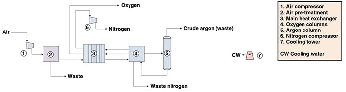
Figure 1. The diagram shows a process for oxygen production via cryogenic distillation
Feed preparation. Initially, atmospheric air is passed through a mechanical air filter to remove dust particles, and compressed to a pressure of about 6 bars. The compressed air is fed to a direct-contact cooler, where it is cooled first with cooling water and then with chilled water. Subsequently, the cooled, compressed air is passed through an adsorbent bed of molecular sieves for the removal of water, carbon dioxide and other trace impurities.
Cryogenic separation. Purified air is then cooled down to nearly liquefaction temperature by means of expansion and heat exchange into a plate-fin heat exchanger (the main heat exchanger) in counterflow against cold nitrogen and oxygen product streams.
Gaseous and liquid air streams from the main heat exchanger are fed to the high-pressure (HP) column, the first of two distillation columns whose purposes are to separate an oxygen-enriched liquid stream from nitrogen. The product from the HP column overhead, consisting of pure nitrogen vapor, is condensed in the reboiler of a second distillation column downstream, operating at lower pressures (the low-pressure (LP) column), and used as reflux for both the HP column and LP columns.
The bottom product from the HP column, a liquid stream rich in oxygen, is split into two streams: part is fed into the LP column, while the remaining amount is routed to the combined evaporator-condenser of the argon column, where it is evaporated and subsequently sent to the LP column.
The LP column overhead, consisting primarily of nitrogen with traces of argon, is fed to the main heat exchanger, where it is warmed by heat exchange against purified air and subsequently compressed. The stream composed of high-purity oxygen, obtained as the LP column bottom, is compressed and vaporized by heat exchange against purified air in the main heat exchanger, and is then routed to nearby consumers via pipeline.
A side-stream rich in argon is withdrawn from the LP column and directed to a column where it is purified from most of the argon and returned to the LP column.
Production pathways
Oxygen can be commercially separated from atmospheric air, via cryogenic distillation and adsorptive separation (vacuum-swing adsorption processes) (Figure 2).
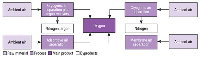
Figure 2. Several variations exist for oxygen production
Economic performance
The total operating cost (raw materials, utilities, fixed costs and depreciation costs) estimated to produce industrial oxygen was about $0.03 per normal cubic meter of oxygen in the first quarter of 2015, including credits associated with sale of nitrogen byproduct. The analysis was based on a large-scale plant constructed in the U.S. with the capacity to produce 3,000 tons per day of O 2.
Edited by Scott Jenkins
Testing the limits of cryogenic distillation
CSIRO (Perth, Australia; www.csiro.au) and the University of Western Australia (www.uwa.edu.au) have developed a first-of-its-kind pilot plant for high-pressure cryogenic distillation processes. “Although cryogenic distillation is practiced in industry and there are some models that can be applied to cryogenic distillation, some gaps remain when it comes to high pressures. The facility will help to fill these gaps and better understand the fundamentals of distillation in temperature and pressure regions not previously explored,” explains Nick Burke, CSIRO research scientist. The plant can operate at temperatures as low as –70°C and at pressures as high as 50 bars, with modifications enabling operation up to 100 bars. A reflux condenser fabricated by CSIRO will allow operation at even lower temperatures.
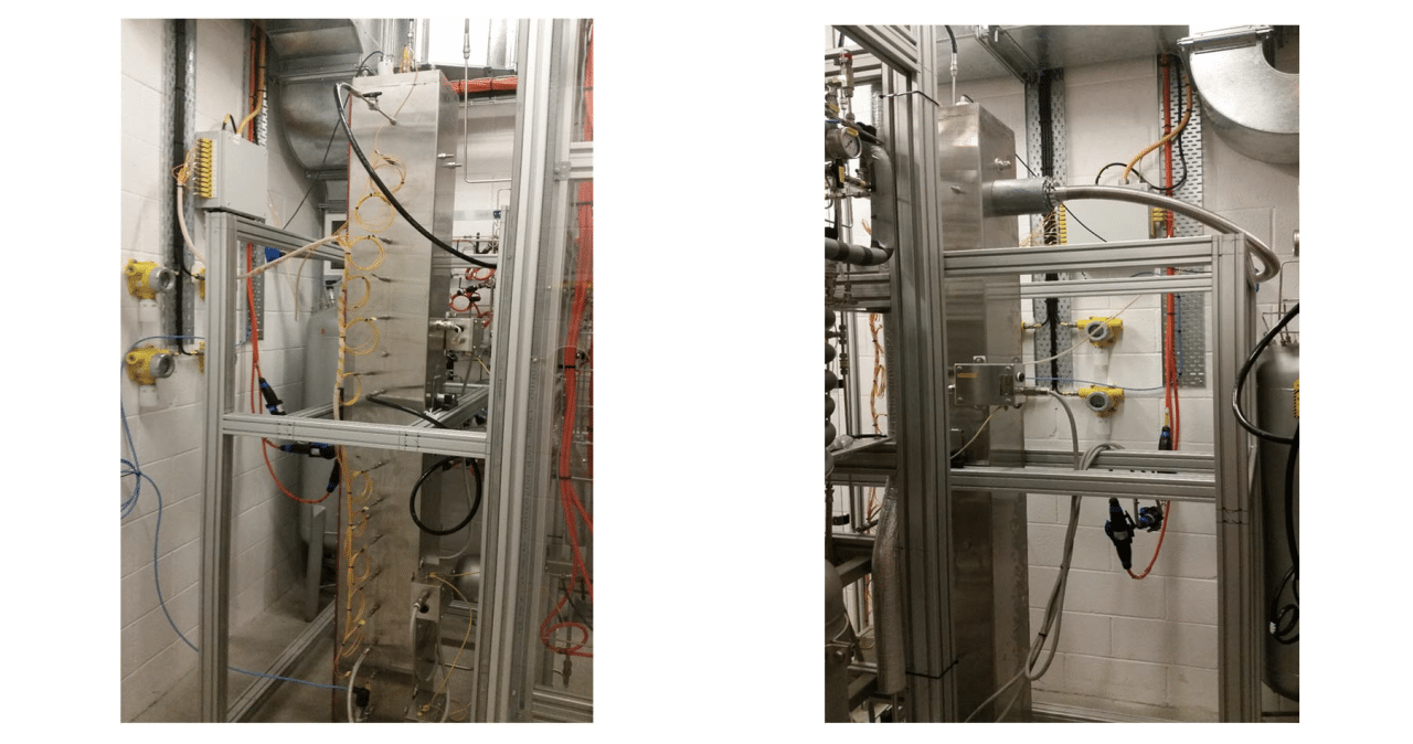
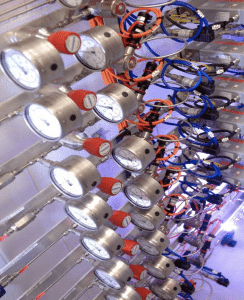
Views of the cryogenic distillation apparatus Source: CSIRO
Currently, the pilot plant’s work is aimed at processes for removing heavier hydrocarbons from natural gas prior to transformation to liquefied natural gas (LNG). “We can test different column internals and can operate under conditions that would not be considered in commercial facilities. In other words, we can push the limits of cryogenic distillation without the threat of deleterious process disturbances,” adds Burke. “Understanding where these limits are will enable industry to better optimize their processes.” He suggests that other applications that could benefit from high-pressure cryogenic pilot runs are air separation, CO 2 removal or noble-gas enrichment. The pilot column is 2 m high with a 50-mm diameter, and its maximum throughput is 20 L/min. The column can operate continuously and has autonomous process control.

Integrated flow control of the pilot plant Source: CSIRO
Also, for floating LNG applications, the pilot plant’s distillation column is designed to oscillate and tilt to mimic motion from wind and waves. “All of the methods for calculating distillation efficiency are based on the assumption of a vertical distillation column. The facility will allow the development of new, more accurate models and methods for tilted and moving columns,” says Burke.