Rethinking Reactive Metal Pipe Systems: A Revolutionary Pipe Product
FREE
REGISTERReactive metals such as titanium and zirconium are long trusted by chemical plant owners, operators, and licensors for corrosion-resistance in demanding high-pressure and high-temperature piping systems. However, these metals are costly and may have design and reliability limitations including toughness and crack growth concerns when used in solid form. Cladding titanium or zirconium alloys to the interior of carbon steel or stainless-steel pipe with very well characterized mechanical properties offers the anti-corrosion benefits of reactive metals at a significantly reduced cost.
NobelClad has developed a unique cladding process that greatly exceeds the loose-lining process, allowing for a substantially higher mechanical integrity across the entire piping system. The product is marketed as DetaPipe™ and can be formed into pipes and elbows and soon into tees, ranging from 3-inch NPS (80 DN) to 30-inch NPS (750 DN). The new pipe adheres to the ASME B31.3 standards and withstands pressure ratings from full vacuum to well above 70 bar (1000 psi). Pipe spools have several connection types such as ANSI B16.5 or ANSI B16.47 flanges, including other commercially available energized seal options.
During this presentation, the authors will present the general mechanical properties and attributes of this clad pipe product, and how it offsets the concerns of using solid refractory metals when handling acids such as acetic acid, acrylic acid, nitric acid, sulfuric acid, urea, and many more.
Offered Free by: NobelClad
Leak Prevention in Small-Bore Piping and Tubing
Improved understanding of the causes of piping leaks can reduce the frequency of leaks and lead to significantly better performance over time
Leakage in pipes is an ongoing problem in research and development facilities across many sectors of the chemical process industries (CPI), such as petrochemicals, pharmaceuticals, food and beverage and others. Leakage can negatively affect operations in pilot plants and laboratory units, and can affect a wide range of laboratory equipment, analytical instruments and testing equipment. Leaks are costly and time-consuming to find, and often are even more expensive to fix. Leaks result in poor-quality data or invalid results, which can require needless rework. Because leaks create unnecessary downtime and program delays, they drain stretched research resources.
Leakage is often ignored or accepted as a “necessary evil.” It is common for scientists and engineers to talk about getting a system “leak tight” as if it is a one-time activity. Yet every system, no matter how well designed or well maintained, is almost certain to leak somewhere at some time. Therefore, leak testing needs to be a routine activity, not a one-time task. Simultaneously, research personnel commonly think of leaks as unfortunate, but inevitable occurrences, like adverse weather conditions — “unfortunate, but what can one do?” As a result of that mindset, few efforts are made to prevent or minimize the frequency of leaks.
Significantly better performance can be achieved over time by (1) understanding the common causes of leaks and (2) taking proactive steps to reduce their frequency. This article focuses on tubing and small-bore piping, which are more common in research and development.
Common causes of leakage
The following items constitute major causes of leakage in piping systems.
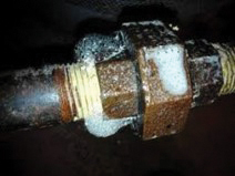
Figure 1. This photo shows a leaking pipe union, probably resulting from being under tightened or forced together during assembly
Improper assembly. Pipe threads are often under-tightened (Figure 1). Undersized wrenches are often used because they are handy or to get more clearance, but this results in the need to exert more force in connecting pipes, which is often not supplied. If upstream and downstream fittings are not properly held, they may slip before the necessary turns have been completed. In order to achieve the desired alignment, fittings are sometimes not tightened all the way. In order to get fittings to match up, they are often tightened insufficiently or forced into place. The former results in a connection that is too loose; the latter produces needless stresses, eventually promoting leaks.
Poorly applied pipe sealant. Pipe sealant is often seen as an area to reduce costs, so inexpensive (and lower-quality) sealants may be used, or sealant material may be applied too lightly. Also, to save time, sealant may be applied unevenly. Tapes are allowed to bunch up due to poor assembly.
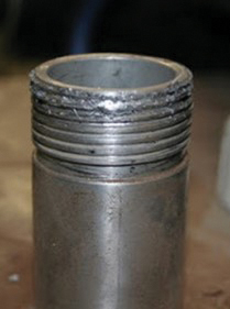
Figure 2. Badly rounded threads like those shown here are almost certain to leak
Badly threaded pipe fittings. Dies for threading pipes are often used well past their lifetimes, resulting in rounded threads that are difficult to seal and are prone to leakage (Figure 2). When standard dies are used to thread high-alloy pipe, they wear out quickly, usually well before anyone realizes there is a problem. Dies are sometimes not started carefully enough, resulting in threads that are not true and are more prone to leaks. Also, pipe threads can be cut too short or too long to make something fit an exact dimension.
Compression fittings are not tightened properly. Pipe fittings are often tightened by “feel” instead of by the number of turns. Worse, many are deliberately under-tightened for longevity. Compression fittings that are routinely removed and replaced will, over time and dozens if not hundreds of cycles, eventually start to leak and need to be replaced. The more the fitting is tightened, the shorter the time until this can happen. Most manufacturers recommend 1¼ turns as a good compromise between longevity and integrity. However, good-quality compression fittings will often seal with fewer turns. So some personnel under-tighten compression fittings routinely to extend their life. But this results in a much greater chance of leakage, as the safety factor inherent in the manufacturer’s recommendations is no longer present.
Tubing inserted improperly. If tubing is not inserted all the way into the fitting and fails to bottom out, this will result in a poor seal.
Debris and scratches. Fitting sealing surfaces and tubing outside surfaces are not generally treated carefully enough. Dirt, grit or foreign materials are often present, albeit in small amounts, but enough to cause gaps or scratches and promote leakage. Poor work practices prevent the fittings or the tubing from staying clean enough. Tubing is often badly scratched from poor handling practices, being dragged along floors, dirt, or other surfaces that produce small scratches that make it more difficult for the system to seal properly. All could be prevented by proper handling techniques.
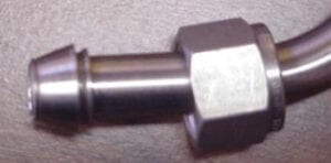
Figure 3. The tubing shown in this photo was probably poorly aligned and felt like it was properly inserted to bottom out in the fitting. It leaked immediately upon startup and the entire piece had to be replaced
Misalignment. Ferrules are left out, damaged, or so badly misaligned that sealing is compromised. Some tubing is not aligned properly (Figure 3). Either it is placed in at an angle or forced into the fitting in such a way that the resulting forces are working against the fitting itself, promoting leakage.
Tubing hardness. For compression fittings to work properly, the ferrules must be harder than the tubing, so they can bite into it (compress) and make a good seal (Figure 4). Thus, every quality manufacturer has a maximum recommended tubing hardness. Sadly, most tubing is bought from local suppliers with no reference to this
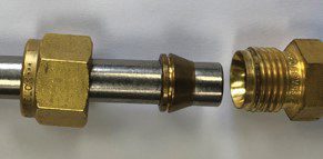
Figure 4. The softer copper ferrule shown in the photo will never seal properly on the harder stainless-steel tubing
property. This often results in tubing that is too hard for a good seal and numerous unnecessary leaks.
Heating and cooling
Routine temperature changes always create more leaks. Whether these are heating or cooling is immaterial. Large (>150°C) or rapid (>25°C/min) temperature swings can cause leakage in as little as one cycle. The author has seen fittings that started out leak-free and properly tightened become less than hand tight at the end of a heating or cooling cycle.
Ambient temperature swings, often routinely ignored, are a significant continuing problem. While slower and of less magnitude, ambient temperature swings happen with a much higher frequency (every day). The frequency more than compensates for the smaller magnitude and greatly promotes leakage. Common problem areas include pipes that are outdoors, in non-air-conditioned process bays, and facilities with significant off-hours temperature changes. Sterilization and cleaning-in-place are often overlooked as a source of the same issue.
Stress and torque
Pipe fittings that are subject to higher stresses and torque tend to leak more easily because these forces work against the sealing surfaces over time. Work on adjacent fittings or components can cause two leaks for each component touched (one on each side). Hold backs, or a wrench or pliers designed to prevent the body of the fitting from moving, are difficult to always coordinate properly. Often, users respond to the turning motion after the stationary fitting starts to move, so it has already been loosened. Other problem areas include equipment, components and pipe sections that are frequently removed. These will leak not only at the disconnect points, but also often at nearby connections. Turning a poorly supported valve increases the potential for the torque to loosen the fitting and cause a leak. Vibrations, bumps and similar shocks from equipment and operations all can contribute to leakage.
Clearance issues
Pipe threads, unions and compression fittings require clearance when connecting and disconnecting to allow components to be removed. It is often difficult to provide sufficient clearance, leading to problems including improper tightening, bent tubing or sprung piping (piping that has been forced together and has significant residual stresses trying to pull it apart). This is often a problem when piping or tubing is deliberately cut short to generate the clearance. In this case, it will tend to spring apart when loosened, allowing for easier removal, but leading to a much higher likelihood of leakage. Flanges and sanitary fittings are commonly pulled apart to make gasket access easier, resulting in stress on nearby fittings. This often results in bending nearby components and increased chance of leakage. Maneuvering to remove a larger, heavier or awkwardly shaped component often results in bumping, banging, leaning on or similarly disturbing adjacent piping and components.
Guidelines to minimize leakage
The following practices will help reduce the likelihood of pipe leakage.
Buy quality components. The adage “you get what you pay for” is very true for pipe and compression fittings. There is a reason why union or connector costs differ drastically from one supplier to the other. Components with lower initial costs will almost invariably turn out to cost more in the end when the costs of finding and repairing leaks are included. Quality always costs more, and many very low-cost fittings are sold primarily on price and are often of poor quality.
Select the proper components for the service. Make sure the tubing you purchase has the proper hardness. Confirm that all the piping components have an adequate pressure and temperature rating with an adequate margin above your highest operating conditions. They need to be suitable for those infrequent times that are hotter or cooler than normal. This is particularly relevant in exterior service, where failing to account for the few days a year above 100°F or below 0°F can create needless problems. Recognize that solar gain (the heat that metals will pick up when exposed to the sun) can be significant (10–30°F). Trying to locate fittings in the shade may help reduce issues but it will only help at best, not eliminate the issue.
Assemble fittings properly. Train all personnel on proper assembly techniques. Leaders should not assume that all personnel know how to assemble fittings correctly, or that they will carefully read the (often cryptic, or missing) instructions. These steps may seem like overkill, but they really do help prevent needless leaks. Gauge compression fittings after assembly to confirm proper makeup. The short time this takes pays rich dividends on showing which fittings need to be tightened. Mark the fitting to indicate the proper number of turns or make sure you have some way to always count them. Make sure the tubing is fully inserted into a compression fitting by either marking the proper insertion depth and making sure it goes in that far or disassembling the fitting to make sure it was done properly. Occasional checks after assembly are often prudent as a quality-control measure. Quality fittings come with the ferrules aligned and the nut just loose enough to insert the tubing. Try to avoid taking them apart before assembly. While perfectly acceptable, it does increase the chances of misalignment and should be avoided if possible.
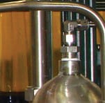
Figure 5. Buying the right fitting would reduce the potential leak points by two, by eliminating the pipe bushing
Consider leakage in the design. Avoid problematic connections, such as pipe threads and pipe unions, particularly in heated or cooled lines or in gas service. Consider where flanges may be a better choice on larger lines and compression fittings on smaller lines (Figure 5). Allow reasonable access to all components and connections, not just the ones you think likely to leak, and particularly those that need higher maintenance. These include: pumps, compressors and similar rotating equipment; filters, purifiers and similar items that need to be cleaned or replaced; and all instrumentation. Some time and effort during the design stage produces much lower leakage rates.
Figure 6. A second support downstream of the valve is necessary to minimize the force from turning the valve
Use holdbacks. Always use a holdback to keep adjacent fittings from being needlessly turned or stressed. Train personnel how to use it properly (Figure 6). This is something that sounds easy until you do it. Support all your valves, or at least all the valves you will turn with any frequency. Individual valve brackets work best, whether homemade or purchased. Supporting valves by clamping the tubing on each side is effective if the supports are close enough. Panel board mounting is not recommended. While it rigidly supports the valves, it is difficult to align all the tubing properly. This leads to frequently forcing it into place with increased risk of leakage. It also makes leak testing harder due to limiting access.
Consider custom fabrications to reduce the number of potential leak points. Waiting a few weeks for a vessel with exactly the ports you need, paying extra for a nonstandard fitting, asking for welded fittings instead of threaded, or specifying an instrument with integral compression fittings instead of adaptors almost always ends up costing less and being faster in the end. It does, however, require some thought during the design and procurement stage.
Minimize the number of joints. Fewer joints mean fewer potential sites for leakage. Bend more tubing instead of using elbow fittings. Use crosses instead of dual tees (four versus six potential leak sites). Purchase reducers that match exactly the sizes you need rather than using multiple fittings. Specifying valves with different inlet and outlet connections, gages with tubing connections, or instruments with tubing connections may cost a bit more and take somewhat longer for delivery, but the savings in time and effort in finding and correcting needless leaks always outweighs these initial outlays. Consider in-house or custom fabricating those things you can’t purchase. Machining specialty fittings, welding two stock fittings together, or getting a custom component manufactured is often feasible. The extra time spent and cost are always recouped quickly through reduced leak testing and locating and remedying leaks found.
Properly mount equipment. Make sure the mounting provides adequate strength to resist the forces that will be applied to it. How often have you seen tubing bent near a cartridge filter that required a wrench to remove or a valve that can be seen to move slightly when it is turned? Substantial-looking brackets can flex in unplanned directions. Often the support for the bracket is too flimsy and flexes. Supporting pipe or tubing to other pipe or tubing is a bad practice. While it can prevent sagging on long runs, it provides little support to prevent leakage.
Pipe removable components properly. Consider how you would assemble and disassemble any component that needs maintenance or changing such as filters, purifiers or traps. How do you remove instruments for calibration or control valves to replace trims? Plan on how you remove them without generating needless leaks. Zero-clearance fittings are well worth the extra cost. Flexible hoses and removable U bends often eliminate or at least reduce needless leakage. This may require extra space during the layout.
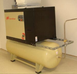
Figure 7. The compressor should have a flexible connection as the fitting on the tank is certain to leak over time
Isolate vibrating equipment with damping pads or springs. Flexible connections to fixed systems, such as compressors, pumps, vacuum pumps and mixers, are important for all piping (Figure 7). Make sure the supporting structure is stiff enough that it does not vibrate or flex during operation. Make sure that any residual vibration is dampened as much as possible. Do not anchor tubing supports to the rotating equipment stand. That usually just transmits the vibration even further.
Carefully design systems subject to temperature changes. Wherever possible, avoid or minimize joints. Instead, use welding, brazing or soldering to eliminate these potential leak points. Utilize specialty fittings and components with fewer joints. Use more leak-resistant components like vacuum fittings. Consider packless valves and similar “sealless” components. Avoid heat tracing if possible and consider small heated enclosures instead. These raise the temperature of all the internal components at a similar rate and minimize leaks due to uneven thermal stresses. Heated enclosures will, unfortunately, still result in piping leaks upon cooling or other temperature changes, but will avoid numerous routine temperature differentials that are always produced by heat-tracing systems. These differentials are certain to increase the number of leaks. The use of heated enclosures also allows modification, leak testing and maintenance without insulation removal and replacement — another cost savings.
Consider keeping the system at a constant temperature when not in service. The extra expense associated with doing so is often more than offset by a reduced leak rate. Provide for gradual heat up or cool down — the slower, the better. Automating the process to slowly ramp up or down over time is often a good way to implement this method. Allow for expansion and contraction, even in shorter runs.
Is it possible to implement all of these suggestions all the time on all your units? Sadly, in the real world, probably not. You likely will not have enough space, money or time to always do everything 100% correctly 100% of the time. But by following these guidelines as much as possible, you can make significant improvements in reducing pipe leakage.
Edited by Scott Jenkins
Author
 Richard Palluzi, PE, CSP, is founder and owner of Richard P. Palluzi LLC (72 Summit Drive, Basking Ridge, NJ 07920; Email: [email protected]; Phone: 1-908-285-3782), a consultancy for the pilot-plant and laboratory research community. Palluzi provides consulting on all aspects of safety and design for pilot plants, laboratories, research facilities and operations. He retired as a distinguished engineering associate after 40 years at ExxonMobil Research and Engineering, where he was involved in the design, construction and support of pilot plants and laboratories for ExxonMobil affiliates worldwide. He is the author of two books, over 100 articles and 40 presentations. Palluzi was chair of the AIChE Pilot Plant Committee, ExxonMobil’s Pilot Plant and Laboratory Safety Standards Committee and ExxonMobil’s Safe Operation Team for its Clinton Facility. He is on the National Fire Protection Association NFPA-45 Fire Protection for Laboratories Using Chemicals and NFPA-55 Industrial and Medical Gases committees. Palluzi also teaches courses for the University of Wisconsin’s Department of Engineering Professional Development, as well as provides customized training to the research community. He holds B.S.Ch.E. and M.S.Ch.E. degrees from Stevens Institute of Technology in Hoboken, N.J.
Pipe Supports: Challenges and Solutions
Pipe supports in industrial process plants are often more complicated than commonly thought. Presented here are some of the challenges that can arise and how to address them
On one level, the topic of pipe supports seems like it should be simple: support the pipe. And sometimes, it is that simple, but most often, it is not. In industrial processing plants, regardless of the process or utility, there are a myriad of considerations when it comes to pipe supports. Concerns such as maximum allowable span for stress, deflection, vibration, harmonics and thermal growth need to be addressed, as well as the interaction among the pipe, its supports and the structures that support those supports. What happens when pipes of various materials of construction, with different allowable stresses, and operating at different temperatures share a common pipe rack? When these conditions are thoroughly considered, proper pipe supports can become more complicated.
This article discusses various pipe-support challenges and some ways to overcome those challenges. It will also point out examples of supports that are either ineffective in the way they are utilized, or much more expensive to install than a simpler approach would be.
Thermal expansion or contraction
Situations involving thermal expansion and contractions of piping are very common in steam and condensate systems, chilled water and cryogenic applications, and in many other process-piping systems. These pipe runs can present multiple challenges, including high anchor loads, nozzle loads on equipment, expansion-loop geometry, or expansion joint selection and placement. The trick is to choose the anchor points wisely. Often, it is necessary to create anchors close to (within 20 feet or so) connecting equipment, such as tanks or pumps, so that the thermal expansion or contraction between the anchor and the equipment can be minimized and more easily controlled with supports, flexible legs, flex joints, springs and so on. The longer runs between these end anchors can be challenging, particularly in congested pipe racks. If expansion loops are necessary, they may block the routing of adjacent lines. Using an up-and-over loop may solve that problem, but might also prevent pipe drainage, require additional steam traps or interfere with other piping, ductwork or electrical runs above. Linear or axial expansion joints might be an option, but care must be taken to address the pressure-induced thrust that might occur. Pressure-balanced (or compensated) expansion joints are a good option, but can be expensive. Ideally, if the pipe run has changes in direction, they can be utilized as flexible legs to allow growth or contraction, as illustrated in Figure 1. The expansion or contraction distance must be determined to properly space adjacent pipes.
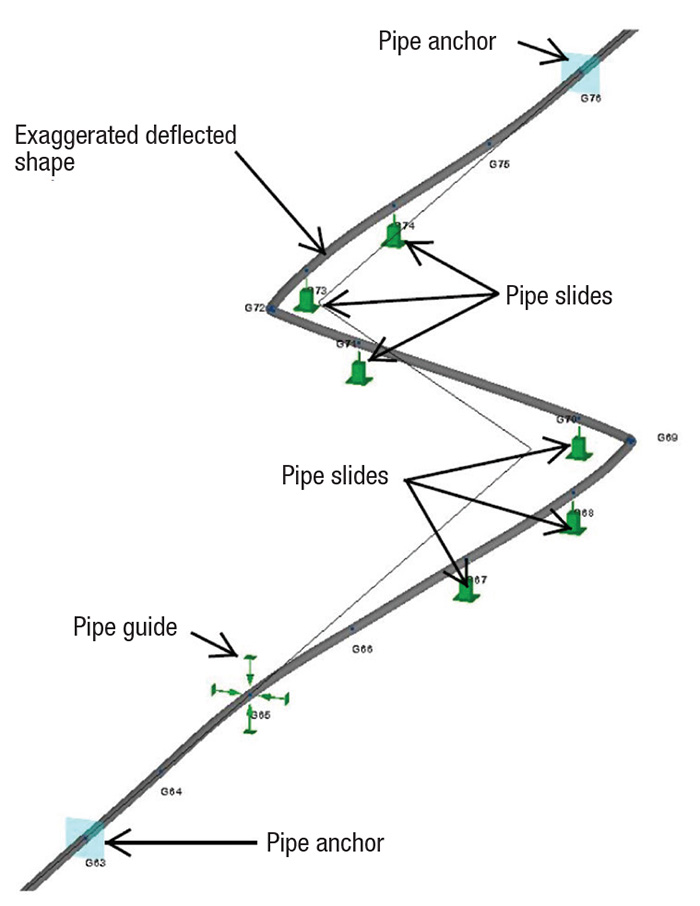
Figure 1. Long pipe runs can be complicated by thermal expansion and contraction, and the distances must be determined
Pipe-induced forces on equipment
Process equipment, particularly devices with rotating components, such as pumps and compressors, are sensitive to forces applied by piping. Reduced seal life and premature bearing wear can result from large forces applied to nozzles. Atmospheric tanks and pressure vessels also have load limits. Loads due to gravity from small-bore piping are generally not a major concern, but loads induced by thermal expansion can be enormous. There are several strategies to reduce these nozzle loads:
1. Create changes of direction in the piping design to allow flexibility and reduce forces
2. Consider designing cold spring into the piping during installation
3. Evaluate the use of spring hangers or supports to reduce thermal and gravity loads across different load cases
4. Consider flexible mounting of the process equipment. Often, high forces can occur on a pump suction — for example, when it is directly connected to a tank with a straight piece of pipe. While the thermal growth or contraction of the pipe segment may only be a small fraction of an inch, the force required to resist the force generated by the expansion can be tens of thousands of pounds. Allowing the pump to float by a 1/16th of an inch can reduce the reaction to a negligible level. This can be achieved by mounting the pump on spring mounts, on a slide base or on threaded rods, allowing them to bend.
5. Expansion/flex joints are an option to reduce loads on equipment nozzles. Unfortunately, they are often incorrectly applied. Due to the pressure thrust forces created by the joint, it is very unlikely that a straight bellows-type flex joint intended to allow axial compression will resolve forces on the pump suction example above, unless the maximum pressure that the system will experience (which is typically test pressure) is very low. These types of joints can be very beneficial, however, in a lateral-displacement configuration, as shown in Figure 2.
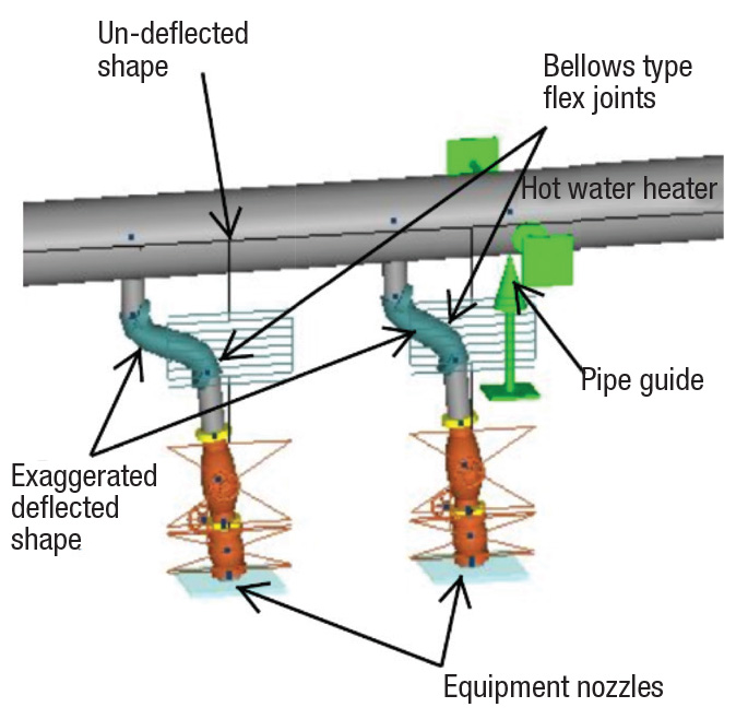
Figure 2. Expansion joints can reduce the loads on equipment nozzles
Sometimes space constraints can complicate supports near equipment, and out-of-the-box solutions need to be found. The images in Figure 3 show supports at pump suctions in a hot-oil system, where the pipe needed to be controlled both laterally and vertically, but also needed freedom to grow away from the pump suction.
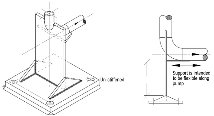
Figure 3. Pipe supports can allow lateral and vertical control, while also allowing freedom to grow
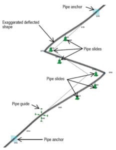
Anchors, guides and slides
Anchors are critical components in any large piping system, and are intended to resist movement from all forces in every direction. They establish the boundaries and the control conditions for all other pipe-stress and support analysis. Anchors are interesting in that they are not just designed to support applied loads, like hangers and guides. Instead, they need to be evaluated for rigidity or stiffness. For example, if an anchor is attached to the top flange of a wide flange beam, the stiffness of that anchor is questionable. Weak axis bending and torsional instability of the beam may reduce the effectiveness of the anchor. If the anchor isn’t relatively rigid, then all other stress and displacement calculations based on that anchor location may be called into question. In designing an anchor, it is critical that the anchor and the structure supporting it are evaluated together to ensure they interact together to achieve the desired performance.
Guides are applied to allow axial movement, generally due to thermal expansion or contraction, and to restrict lateral movement due to wind loads, plant vibrations, or even seismic forces. When a pipe is running along a pipe rack with regularly spaced support beams, the selection and evaluation of the guides is simple. For these situations, many off-the-shelf guides from pipe manufacturers exist. Selecting guides for some other conditions can be more challenging — for example, a pipe running a few feet below roof steel, or vertically a couple of feet off structural steel. In these instances, an off-the-shelf catalog guide probably won’t work without incurring significant costs in additional structural steel. A low-cost solution for examples like these is to use pipe clamps, and either angle iron braces or threaded rod and turnbuckles to create two-force members that provide support in two directions, but allow axial movement via the slight bending of the two-force members (Figures 4 and 5).
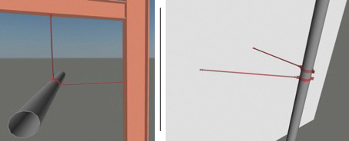
Figure 4 (Left). Pipe clamps and braces can provide support in two directions, while also allowing axial movement
Figure 5 (Right). Axial movement can occur via the slight bending of the two-force guides
Slides are applied in very similar instances as guides and are typically used together in thermal expansion and contraction applications. Slides provide support in one direction (generally perpendicular to the pipe), most commonly supporting a horizontal pipe from below. Like guides on a pipe rack with regularly spaced beams, slides can be selected in a straightforward manner, and there are many off-the-shelf slides available. They are typically selected to allow two degrees of freedom, usually lateral and axial. But once again, in instances where there is not a uniform framing level to support the slides, the alternatives must be investigated. In many cases, a simple clevis hanger can be used, as long as the hanger rod is long compared to the expected displacement of the pipe.
Practical pipe supports
Taking a practical approach to pipe supports can simplify the design of the support system and can usually make supports less expensive. The following are some examples of not-so-practical supports, along with a brief explanation as to why they are impractical, and a better alternative to the example.
Tall post with pipe slide, guide, or anchor on top. A tall post is likely going to experience a relatively large deflection at the top, depending on the section properties of the post, and even with a polytetrafluoroethylene (PTFE; Teflon) or ultrahigh-molecular-weight (UHMW) polymer slide or guide, there is still a friction force that will be applied to the post (Figure 6).
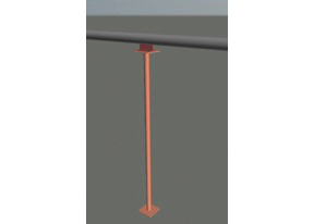
Figure 6. A tall post with a pipe slide, guide or anchor at the top is likely to experience relatively large deflection at the top
The practical approach is to evaluate the expected displacement that necessitated the slide or guide, and check to see if the post and its bottom attachment (weld or base-plate anchors) can tolerate that deflection and bending moment. If it can, then the slide or guide is likely not needed, and a simple U-bolt might suffice (Figure 7).
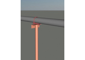
Figure 7. If the post can tolerate bending, then a U-bolt clamp may work as a pipe support
In the case of an anchor on a tall post, the anchor needs to be evaluated for the stiffness of the post to make sure the resulting deflection doesn’t create issues in the rest of the piping system. And again, a U-bolt may be able to transfer all the load the post can handle. Buckling stability of the support needs to be taken into consideration in all cases, but especially if the post is not a closed section member.
Tall post with a cantilever, and either a pipe slide, guide, or anchor. This case is very similar to the one just described, and is commonly seen in retrofitted or expanded plant areas. The principles are the same, but with torsion of the post added (Figure 8).
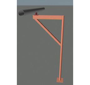
Figure 8. One concern surrounding tall posts with cantilevers involves the torsion of the post
The support is likely flexible enough that slides or guides are not necessary, and this can easily be proven by comparing the expected displacement of the pipe to the deflection resulting from the calculated friction force from the slide/guide. If the friction force is enough to deflect the support to a degree that is equal to or greater than the anticipated pipe displacement, then the slide or guide should not be needed, because the support will bend before the slide or guide begins to move. Again, buckling stability of the support needs to be taken into consideration, especially if the post is not a closed section member.
Long threaded rod hanger and adjustable pipe roller. This is another case that is commonly seen, and like the case of the tall post, the stiffness of the threaded rod hanger is likely not enough to provide the resistance needed to cause the roller to roll, so the roller will just act as an expensive clevis hanger (Figure 9).
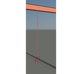
Figure 9. The stiffness of a rod hanger, like the one shown here, likely will not provide the resistance for the roller to roll
Pipe support design and engineering, like all other areas of engineering in an industrial plant, can be challenging. With a little understanding of the various situations, and by not always resorting to an off-the-shelf solution, the design can often be made simpler, more reliable, less expensive and easier to install.
Edited by Scott Jenkins
Author
 Scott Feller is the executive vice president of operations at AMG, Inc. (1497 Shoup Mill Rd, Dayton, OH, 45414; Phone: 937-260-4630; Email: [email protected]). AMG, Inc. is a full-service engineering consulting firm that provides a broad range of design and construction support services to various chemical processing and related heavy industrial segments.
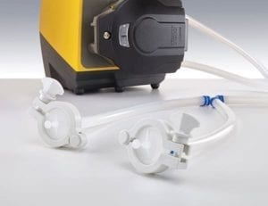
Sterile and customizable tubing systems for bioprocessing

Watson-Marlow Fluid Technology Group
The puresu range of single-use tube assemblies for bioprocessing applications (photo) has now been expanded to include three new product options: sterile-claim, gamma-irradiated and non-irradiated. Leveraging an open-architecture design by using puresu single-use components, users can quickly create a sterile fluid path that meets specific bioprocessing needs. Sterile puresu components are optimized for critical fluid-path bioprocesses and users who require contamination-risk mitigation. Gamma-irradiated puresu products are suitable for users who manage microbial control through bioburden reduction. Non-irradiated puresu components are designed for process-development activities. A variety of fluid-path components are offered, including tubing, tubing fittings, sanitary hose barbs, bio-clamps, valves and adaptors. — Watson-Marlow Fluid Technology Group (WMFTG), Cornwall, U.K.
Facts at your Fingertips: Pneumatic Conveying Challenges
Among the key benefits offered by pneumatically conveying bulk solids is the ability to route materials around obstructions in the plant using bends in the pipeline. However, these changes in direction involve a considerable number of particle impacts on the bend wall as the particles make the turns. This one-page reference reviews the potential problems that can arise from particle impacts in pipe bends of dilute-phase pneumatic-conveying systems.
Bend geometry
Pipe bends can take a variety of different geometries, which can have a significant influence on particle impact angle. Basic long-radius bends are the most commonly used because they provide the most gradual change in direction for solids, and because the angle of impact on the pipe wall is relatively small, which helps to minimize the risk of attrition or erosion.
Common-radius bends are made by bending standard tubes or pipes (Figure). The radius of curvature, RB, may range from 1 to 24 times the tube diameter, D. Common-radius bends can be loosely classified as follows: Elbow (RB /D = 1 to 2.5); Short radius RB /D = 3 to 7; Long-radius (RB /D = 8 to 14; Long sweep (RB /D = 15 to 24).
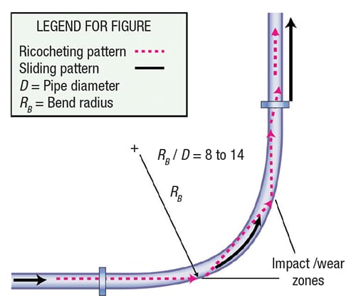
Figure. Flow in a standard, long-radius bend is illustrated here, with typical flow patterns, wear points and reacceleration zone shown
Pressure drop related to bend
As particle impacts occur, particularly against bends, there will be a significant reduction in particle velocity. These particles will then have to be re-accelerated back to their terminal velocity, which will add significantly to the pressure drop — and hence, energy loss — for the conveying system. This is particularly true after short-radius bends.
The pressure drop in a bend depends on the ratio of bend radius to pipe diameter, the gas velocity, Ug, and the internal roughness, k, of the pipe. When a two-phase, gas-solid suspension undergoes a directional change in a pipeline, the bend naturally acts as a segregator of the two phases. Centrifugal forces act on the particles, concentrating them near the outer wall of the bend. Friction coefficients within the bend will be different than those in the adjacent straight sections.
Abrasion of pipe wall
If the material to be conveyed is potentially abrasive, significant wear of the pipeline, especially at the bends, is likely to occur. With a new bend, the particles tend to travel straight on from the preceding straight pipeline until they impact against the bend wall. After impact, they tend to be swept around the outside surface of the bend. They are then gradually entrained in the air in the following straight length of pipeline.
Attrition of particles
If the material being conveyed is potentially friable, damage to the material being conveyed may occur, and it is possible that these changes to the material could affect the conveying performance of the material itself.
Particle breakage. Particle breakdown occurs by three main mechanisms. The first is to shatter or degrade when the bulk solid is subject to impact or compressive loading. The second is for fines and small pieces to be worn away by attrition when bulk solids either rub against each other or against some surface, such as a pipeline wall or bend. The third is for the materials, such as nylons and polymers, to form “angel hairs” when conveyed, as a result of micro-melting, which occurs to due to the frictional heat of particles sliding against pipeline walls.
Operating problems. Particle degradation can cause problems in a number of areas because of changes in particle shape and particle-size distribution that can result. Plant operating difficulties are often experienced because of the fines produced, and problems in handling operations can also result after the material has been conveyed. Apart from the obvious problems of quality control with friable materials, changes in particle shape can also lead to subsequent process difficulties with certain materials. The appearance of the material may also change, making it out of specification.
Filtration problems. In pneumatic conveying systems, plant-operating difficulties can result if degradation causes a large percentage of fines to be produced, particularly if the filtration equipment is not capable of handling the fines satisfactorily. Filter cloths and screens will rapidly block if they have to cope with unexpectedly high flowrates of fine powder. The net result is that there is usually an increase in pressure drop across the filter, and this could be a significant proportion of the total pressure available in a low-pressure system.
Flow problems. In many systems, there is a need to store the conveyed material in a hopper or silo. Flow functions can be determined for bulk particulate materials, from which hopper wall angles and opening sizes can be evaluated, to ensure that the material flows reliably at the rate required. A change in particle-size distribution of a material, as a result of conveying operations, however, can result in a significant change in flow properties. Thus, a hopper designed for a material in the “as-received” condition may be totally unsuitable for the material after it has been conveyed. As a result, it may be necessary to fit an expensive flow aid to the hopper to solve the problem.
Editor’s note: This “Facts at your Fingertips” column is based on infomration from the following articles: Dhodapkar, S., Solt, P. and Klinzing, G., Understanding Pipe Bends in Pneumatic Conveying Systems, Chem. Eng., April 2009, pp. 53–60; and Mills, D., Particle Impact Problems in Pneumatic Conveying, Chem. Eng., March 2017, pp. 69–76.

Pipes, Tubes and Fittings
This pipe-milling end-prep tool is for beveling boiler tubes

Esco Tool
The Esco Wart Millhog (photo) is a pipe-beveling machine that is designed for making repairs to water-wall boiler tubes. It features a rigid-inner-dia. clamping system, and uses titanium-nitride-coated cutter blades to machine carbon steel or highly alloyed tubes without the need for cutting fluids. The machine is able to bevel, face and bore simultaneously, with relatively simple tooling changes, says the company, and it is designed to machine water-boiler tubes with inner dia. from 2 to 3 in. The machine is sealed to prevent debris from entering the tool. It rigidly attaches to the tube with clamps that fit the inner dia. and expand on the mandrel using a self-centering, draw-rod assembly and attached wrenches. The machine is available with both pneumatic and electric motors. It is available for purchase or for rent. — Esco Tool, Holliston, Mass.
Faster fluid management for biopharmacuticals
Lynx CDR connectors allow efficient fluid management through sterile connection, disconnection and reconnection, providing an alternative to the more time-consuming tube-welding processes and costly manifold configurations traditionally used in upstream and downstream biopharmaceutical processing. The connectors provide six sterile connections, disconnections and reconnections from one disposable device. Previous disposable connector technologies allowed users to make only a single sterile connection per device, requiring the use of multiple devices per unit operation. According to the manufacturer, the Lynx CDR’s ability to perform connections and disconnections with a wet, pressurized flow path allows for more economic fluid management than with connectors that require a dry, non-pressurized flow path. — MilliporeSigma, Billerica, Mass.
