Properly sized ejector stations can save capital costs and reduce downtime
Steam-assisted, gravity-drainage (SAGD) operations employ large tanks that vent flammable and sometimes toxic gases. Safety and environmental concerns often require engineers to design vapor-recovery units (VRUs) to collect these gases and redirect them to a useful location — frequently for use as a fuel gas in a steam-generation system.
When choosing a VRU setup for an SAGD facility, the two most common options are compressor-based and ejector-based designs. Compressor control and recycle schemes enable greater operating turndown, allowing the compressor to operate over a range of flows and providing better control. Similarly, compressors can accept small upsets with little or no action required by the staff. By contrast, each single ejector is either on or off.
Compressors frequently run on electricity or burn fossil fuels in an engine. Ejectors, on the other hand, require a motive gas from a high- or medium- pressure pipeline. The energy comes from the pressure of the stream, and none of the fluids are consumed inside the ejectors. One potential drawback, however, is that single ejectors have effectively no turndown capabilities. Thus, they lack the operating flexibility of compressor-based VRUs.
The use of an ejector station — which involves a group of ejectors operating in parallel — can overcome the flexibility constraints of a single ejector. Figure 1 shows how a three-ejector station is set up. Operators activate individual ejector units according to tank-venting rates. As the tank pressure increases, additional ejectors are activated to relieve the increased vapor flow. When tank pressures decrease, operators deactivate individual ejectors until the tank pressure has stabilized to a desired setpoint.
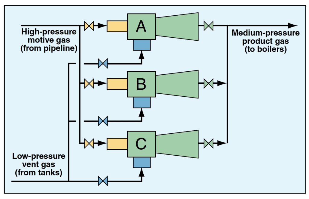
The ability to maintain fine control using a multi-ejector-based VRU can help avoid unwanted scenarios. For instance, operating ejectors below the required flowrate can result in tanks venting their vapor contents to the atmosphere. Similarly, operating ejectors at flows higher than necessary may require flaring if the downstream steam generators cannot accept the increased gas flow. The need for flaring is not only expensive, but it increases carbon emissions, and prolonged flaring may require a plant shutdown for regulatory compliance. Facilities are most likely to flare when steam generators become deactivated but production at the facility — and therefore tank venting — continues. An engineer can reduce the likelihood of flaring by efficiently sizing ejectors and turning off any ejectors that are not required to relieve pressure from tanks. The method of staggering ejector sizes in parallel service (discussed below) gives operators maximum control and can help reduce flaring.
The primary considerations before determining the VRU arrangement are the desired VRU maximum capacity (referred to here as 100%), and how stable the flowrates are. If an ejector station is chosen instead of a compressor, designers must also decide how finely to control the system.
Increasing the ejector count inside a station increases the number of control points (or steps) for the system, leading to finer control. During normal operation, the vented flowrate may be 45% of the maximum required capacity of vented gas. For example, if a tank system vents 600 kg/h of gas as a maximum case scenario, and the ejector station runs at 45% capacity, then the vent gas is moving through at 270 kg/h. To handle 45% of the maximum vented flowrate, the operator activates ejectors until the vented flow requirements have been satisfied.
For this case, if we have four ejectors, each able to handle 25% of the maximum flow to the ejector station, we will need to activate two of the four ejectors. If, however, the design uses three ejectors, each capable of handling 33% of the max flow to the ejector station, we would need to activate two of the three ejectors, and our control wouldn’t be as fine. The use of more ejectors allows a larger number of steps between 0 and 100% to be activated, providing more control points and finer operating control.
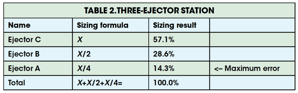
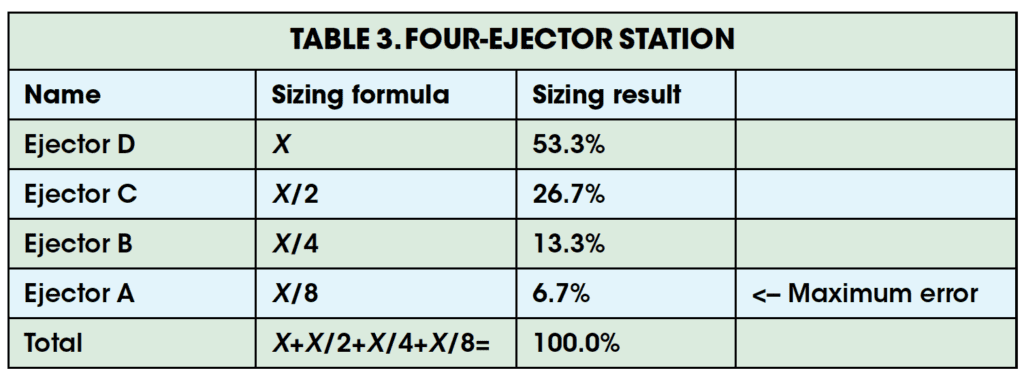
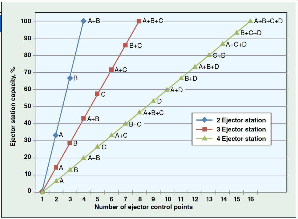
Table 1 shows the most efficient way to stagger the sizes for a two-ejector VRU station. The X term in Tables 1, 2 and 3 refers to the size of the largest ejector in that station. For instance, for the two-ejector station in Table 1, X refers to 66.7% of the maximum vent rate. For the three-ejector station in Table 2, X refers to 57.1% of the maximum vent rate. For the four-ejector station in Table 3, X refers to 53.3% of the maximum vent rate.
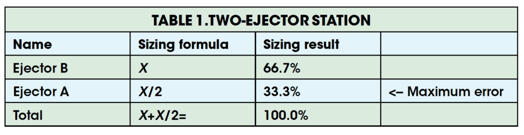
The maximum error notes the largest difference the setup can have between the vent gas flow and the flow of vent gas through the ejectors. Every unit of vent gas requires about five units of motive gas for the ejector to operate properly. So if vent flows become large, the motive gas flows become much larger, and could overwhelm the boilers, requiring excess product gas to be burned in a flare system.
In general, a two-ejector system is preferred when the maximum vent-gas flow to an ejector station is relatively small. For such small vent rates, fine control is not usually required as the boilers can accept the relatively small amount of added gas.
Table 2 shows the most efficient way to stagger the sizes for a three-ejector VRU station. Such a design is useful when the total flow from several ejector stations could send more fuel to the downstream steam generators than they can accommodate. This setup can also handle sizable fluctuations without the need to activate or deactivate ejectors in the station.
Table 3 shows the most efficient way to stagger the ejector sizes in a four-ejector VRU station. This arrangement allows for tight flow control, so it is suitable for ejector stations with large flows. But, it requires careful monitoring to ensure that fluctuations do not create system problems.
Increasing the ejector count at a station with more than four ejectors provides even finer control. However, optimizing ejector control using five or more ejectors in a station (maximum error = 3.2%) does not allow much room for fluctuations in the process, and requires close monitoring.
Based on the ejector sizes provided in Tables 1, 2 and 3, Figure 2 provides a visual representation of how finely operators can control ejector stations. Each point on the graph indicates a setpoint to which the ejector station can be controlled. n
Author

Graeme H. Bryden is a process design engineer working in the Vista-IMV Joint Venture Corp. (2nd St., S.E., Suite B12, 6020, Calgary, Alta., Canada; Phone: 403-538-0888:,E-mail: graeme@ghbdesign.com) designing SAGD facilities. He holds a B.Eng. in chemical engineering from Dalhousie University, and is a P.Eng.