Measuring temperature is required in nearly all chemical processes, but engineers often struggle with implementation. Here are suggestions to avoid common pitfalls
Measuring temperature in chemical processing applications remains, arguably, the most misunderstood of the four main process variables, which are flow, level, pressure and temperature. Complexity arises from process requirements of an application — such as where and how to locate a sensor — and from the sensing technology itself.
In this article, we examine one particularly challenging application that incorporates many application-side problems, then dig into sensor and transmitter capabilities and trade-offs.
Where to measure?
One of the challenges of temperature measurement is dealing with process inconsistencies. Temperature is rarely homogeneous. For example, imagine a large vessel of liquid: natural convection will cause stratification such that the contents near the bottom will likely be cooler than at the top. So, where is the ideal place to take a temperature measurement?
In the real world, the answer may be everywhere. Say the vessel is a reactor and feedstocks mix over a catalyst bed to create an exothermic reaction. A process engineer attempting to optimize the reaction will want to determine a temperature profile throughout the contents, since it indicates how and where the feedstocks are interacting. Temperature details help determine if the reaction can be made more efficient, if the feedrate needs to be changed, or if some other configuration element should be modified.
Temperature, under these conditions, cannot be measured from a distance, and a single temperature sensor can only measure its immediate surroundings. If many readings are desired throughout the vessel in different locations — such as in a distillation tower or reactor — multiple sensors are required at those strategic points. This means if a location one meter inside the vessel is required, there must be a 1-meter-long probe. And if fluid is moving around inside, or flowing through a pipe, the probe must withstand the movement. Given these mechanical challenges, plus possible interference from agitators or level measuring devices, it is no wonder complex multipoint measuring challenges are some of the most difficult to solve.
Solving multipoint measurement
An effective multipoint solution must fulfill the following list of process requirements:
• Probes extending into the vessel interior must have sufficient mechanical strength to avoid breaking, and they must be made from materials capable of withstanding the temperature and chemical environment
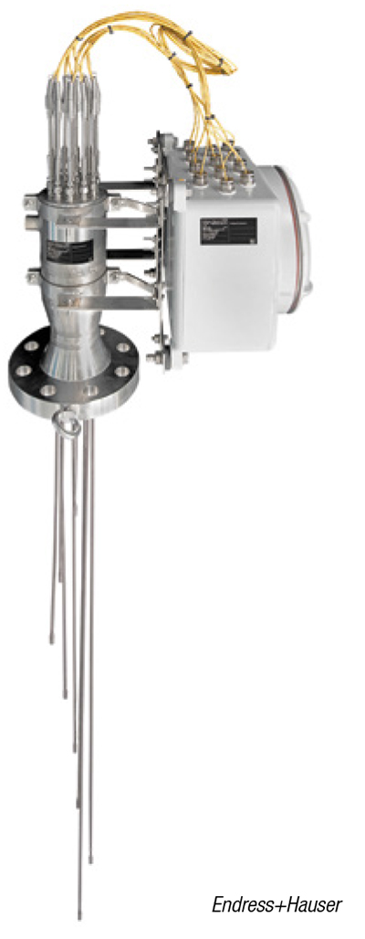
FIGURE 1. Some applications callfor individual probes stemmingfrom a common mount that can bebent as needed to cover the space
• A probe can and often should include multiple temperature sensors (Figure 1) along its span to minimize the number of penetrations while increasing measurement points. Probes can also be curved where practical to improve placement options
• Identical sensors must be used in each location, plus probe wall thickness must also be uniform, to deliver consistent and accurate readings with similar response time. It is only under these conditions that an accurate and dynamic temperature profile can be determined
Putting these requirements into practice means balancing multiple trade-offs, as follows:
• While a resistance temperature detector (RTD) generally offers more consistency and accuracy than a thermocouple (TC), TCs tend to win out in multipoint applications due to their durability, fast response, and ability to pack into compact packages with minimal insulating material
• Probe materials must be corrosion resistant. However stainless steel and other exotic alloys frequently have low thermal conductivity, slowing response time. Adding wall thickness for strength and internal protective insulation makes the problem worse, so careful probe design is critical
• Probe locations must minimize internal blockage, particularly in areas near catalyst beds
• Constructing probes as thermowells allows for sensor removal, but also usually results in thicker walls and internal gap. This results in slower response
Effective results
Building highly-effective probes requires expertise and optimum component selection, but the positive results speak for themselves. A petroleum refinery wanted to develop a temperature profile across the catalyst bed of a hydroprocessing unit that routinely handled crudes with significant hydrogen sulfide content (Figure 2). In this aggressive environment, corrosion of probes and wiring is a constant issue, causing temperature measurement inconsistency and outright sensor failure.
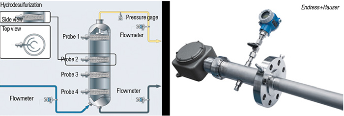
FIGURE 2. Using a multipoint temperature probe (right), a petroleum refinery created an accurate temperature
profile for a catalyst bed (left) without causing obstruction problems
After an examination of optimal sensor placement, it was possible to design probes to reach all strategic measurement locations with minimal catalyst bed blockage. Clever probe design — using a hydrogen sulfide-resistant alloy in addition to internal wire protection — made it possible to deliver sensors that withstand the harsh environment, while providing consistent and directly comparable readings, capable of generating a true temperature profile necessary for process modeling and analysis.
Sensor characteristics
The debate of TC versus RTD as an ideal universal sensor technology continues, but fortunately, there is no need to make an either/or decision. Each has its niches, depending on process requirements, although the parameters of the traditional discussion are always evolving. The two methods are conceptually different, and they are worth a brief look (Figure 3).
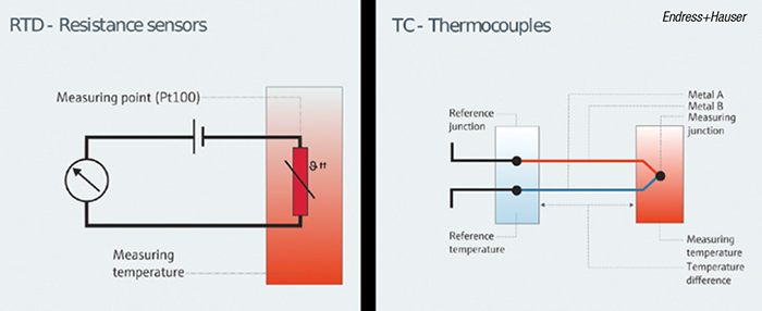
FIGURE 3. RTDs (left) and TCs (right) are different conceptually. TCs modulate voltage, whereas RTDs modulate resistance. Both require specialized cables to send their measurement over any distance
A TC works on the basis that a wire subject to a temperature gradient also creates a corresponding voltage gradient, and different alloys respond differently to the same temperature gradient. Consequently, a TC uses two dissimilar alloys, joined at one end, as the sensor. Temperature is calculated based on the voltage difference, but to determine the absolute temperature at the sensor, there must be a known temperature reference. This is where the terms “sensing” (hot) junction and “reference” (cold) junction, two ends of the electrical circuit, are derived from.
TCs are easy to make, and can be optimized using specific alloy combinations (designated as types) to cover different ranges. Generally, TCs are valued for fast response and durability. However, they often take a back seat in accuracy and repeatability, because any change in the electrical characteristics of the wires can cause a reading shift or drift. Drift is typically the result of corrosion at some point along the lengthy electrical path.
An RTD operates on the basis that various metals change electrical resistance according to temperature. Platinum is very good for this purpose, and the sensor uses a tiny coil of fine platinum wire as the sensor. The circuit measures resistance, and to avoid changes related to the lead wire’s resistance, multiple lead wires — usually three or four — cancel out this element electrically. RTDs are valued for their accuracy and repeatability. However, they are more fragile and the protection they require slows their response time.
New manufacturing techniques have resulted in more robust RTDs that do not require as much protective insulation, providing faster response times. And for TCs, improved electrical insulation better protects lead wires from corrosion, resulting in less severe drift.
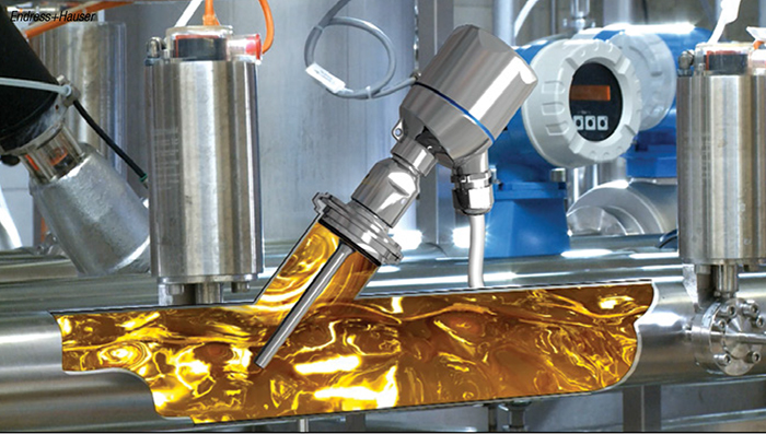
FIGURE 4. Measurements taken in a moving liquid stream by a sensor encased in a thermowell tend to be slow due to heavy protection, but modern variations, like the probe pictured, provide durability and strength without sacrificing response
For example, a food processor switched to modern, fast-responding RTDs (Figure 4) for an ultra-high temperature treatment process. After a series of tests, plant engineers found these new sensors reduced response time by more than 50% compared to previously installed sensors. This allowed for tighter temperature control, maintaining the process within a very narrow range necessary to optimize production.
Avoiding signal degradation
The signals created by RTDs and TCs are not very robust, and they can be difficult to transmit over long distances without degradation. In fact, most problems related to drift are more attributable to wiring and termination issues than sensor problems. Additionally, temperature sensors require specific, homogenous cabling that is specialized, and usually very expensive.
For this and other reasons, it is typically most practical to install a temperature transmitter as close to the sensor as possible, to convert the raw voltage or resistance signal to a more transmittable format. For example, when measuring moderate temperatures, most TCs create a signal less than 15 to 20 mV, so a very small change can represent a significant temperature movement.
A transmitter turns the raw analog output from the sensor into a more robust signal, such as a 4–20-mA current loop or digital fieldbus. Some transmitters are dedicated specifically to RTDs or TCs, but most are universal and can handle resistance or millivolt inputs. When working with TCs, a transmitter provides an internal reference junction and can be set to convert multiple TC types. These versatile internal capabilities also help provide instrument diagnostic information.
Transmitters come with a variety of options, and at the most basic level, simply convert the sensor output into a communication-optimized format. For many applications, this may be all that is necessary, and this usually costs less than buying spools of specialized cable required to connect multiple sensors to the automation host system.
The “hockey puck” configuration, mountable on a sensor, is very common in chemical plants. But for hazardous locations, separate housings are often required, frequently with a local display.
Most transmitters can work with RTDs or TCs, and can be configured using the HART communication protocol superimposed on the 4–20-mA analog current loop, or via another digital protocol, such as Foundation Fieldbus or Profibus PA. Additionally, modern “smart” transmitters enable configuration wirelessly via Bluetooth, requiring only a smartphone or tablet application to set up.
Diagnostic capabilities
Today’s sophisticated field instruments provide diagnostic capabilities, but there is little consistency in the ways these work from manufacturer to manufacturer. Some have adopted the NAMUR 107 standard to create a higher degree of uniformity when presenting diagnostic information, so reliability teams and operators can more easily understand what a device is communicating. This includes notifying users when a sensor needs to be checked, when maintenance is required, when measurement accuracy falls out of specification, or when an instrument fails outright.
FIGURE 5. Advanced transmitters monitor sensor health and can perform signal conditioning in the field, before signals even make it to a host automation system
Temperature transmitters have specialized diagnostics that differ from pressure or flow instruments. Highly sophisticated transmitters, such as the one shown in Figure 5, can examine sensor health and perform signal conditioning at the field level, before even sending a process value measurement to the host automation system.
The following are examples of diagnostic features:
• A single transmitter can accept signals from two identical sensors installed as a redundant pair. It compares the two, and if the values begin to diverge, it can notify operators of a developing issue
• When two sensors are in use, if one fails, the transmitter can maintain the operating sensor while alerting operators of the other failed sensor
• If leakage to ground is detected anywhere in the loop, the transmitter can create an alert
• Where a TC is in use, the transmitter can use its resistance measuring capability to check the lines periodically. If a resistance change is detected, the measurement is likely questionable
• Some transmitters can log readings over multiple days, helping troubleshoot situations in which readings change without a process-related cause
Creating better applications
When analyzing a new temperature-measurement application or trying to improve an existing one, it is important to consider a variety of questions. These often include the following:
• How critical is the measurement? Is it being used for control, or simply monitoring? This helps determine the need for redundant sensors, sophisticated diagnostics and other reliability considerations.
• How accurate must the measurement be, or is consistency equally useful?
• How quickly can the process temperature change, and how much does it move? If the process does not move quickly and avoids wide swings, ensuring fast response may not be necessary.
• Will alarming or safety elements be attached to this measurement? Many sensors and transmitters are safety certified, but their use does not automatically result in a proper safety-instrumented function.
By partnering with a knowledgeable supplier, processors can sort through these questions, determining relative importance and balancing trade-offs. These considerations can enhance understanding of the complex topic of temperature measurement, helping optimize applications for product quality, plant sustainability and production profitability.
Edited by Scott Jenkins
Authors
 Greg Pryor is the product marketing manager for temperature and systems products at Endress+Hauser USA (2350 Endress Place, Greenwood, IN 46143; Phone: 888-363-7377 Email: info.us@endress.com). He has national responsibilities for the strategic direction of the temperature business unit, including product portfolio management, technical and application support, and marketing and business development for temperature and systems products. He has a bachelor of business administration (BBA) degree in marketing from Texas A&M University. Based out of Houston, Texas, Pryor has over 20 years of experience in temperature measurement instrumentation.
 Kris Worfe is the chemical industry manager at Endress+Hauser USA (same address as above). He has national responsibilities for the strategic direction of the chemical business, including product portfolio management, technical and application support, and marketing and business development for the chemical industry. He has a BBA from Texas A&M University. Based out of Houston, Worfe has over 22 years of process automation experience.