When plants are built with excessive design margins, problems can arise when operating under turndown conditions. This article helps explain how overdesign tends to occur and how to avoid problems when operating at turndown
Operating under turndown can be problematic, especially where the plant has well-intentioned, but excessive design margins. An “over-designed” plant can help meet future demands on the plant, but can fail to perform during a turndown requirement. This article helps to understand some of the causes, consequences and mitigation measures needed to properly manage plant design for a turndown requirement.
Establishing design margins on plants and equipment is a common practice, and they are provided for a variety of reasons. Among these are anticipated downtime, future deterioration expected for equipment in plants built to last 20 years, and of course, standard engineering practice. Engineers generally love design margins, because using them makes them feel safer. “Just in case” scenarios include adding an extra 10% to a design margin to make sure the equipment meets its performance guarantees.
In another scenario, engineers might add an extra 10% in design margin because of the uncertainties in design basis composition and/or the simulation model used. The thinking is that with multiple design basis compositions, the prudent choice is to design for the worst-case scenario. In one project the author was involved with, there were two trains handling different process fluid compositions. One needed a large compressor, but the other generated a very small amount of gases. Because the two trains needed to be similar (just in case one train breaks down), one of the trains operated with an oversized compressor, which mostly ran on recycle during normal duty. (The team managed to remove a compressor with the help of an understanding client).
An important hidden pitfall of unintended overdesign is the extra capital cost incurred. This can add unnecessary cost to the product, or lower the return on investment without contributing to well-intentioned excess plant capacity.
As the regulations on emissions tighten, the ability to meet these norms during turndown are also coming under scrutiny. For instance, uncontrolled flaring during startups and shutdowns is no longer acceptable to the U.S. Environmental Protection Agency (EPA). A flare-management program needs to be put in place to address and minimize these situations. Environmental regulations put enormous pressure on managing emissions during turndown, especially for equipment that meets the norms only during a “best-case” efficiency envelope. Going forward, carbon emissions are increasingly coming under the attention of authorities. Failing to operate under the best efficiency conditions may incur a penalty in the future.
Another somewhat more insidious negative consequence of overdesign is the extra operating cost penalty when operating at off-design conditions. Most equipment is designed for a maximum efficiency envelope. Operating beyond these envelopes (on the lower and higher capacity) leads to increased utility consumption. Centrifugal compressors with a limited turndown (typically 70%) will recycle gases, and the penalty can be significant depending on the compressor power. Similarly, distillation towers can operate at a turndown depending on the type of trays and can easily be over-refluxed. Higher vapor-liquid traffic in a distillation column means higher steam consumption in the reboiler, and a higher condensing duty. The worst part of these scenarios is that the operator can easily miss the higher consumption rates. For operations personnel, stable distillation column operation is much more important than a higher utility consumption.
Example scenario
To illustrate how easy it can be for a plant to be “overdesigned,” consider this particularly nasty scenario. Begin with the typical design basis, which states the following:
- Design for worst-case scenario
- Hours of operation are 8,000 per year
- Provide turndown of 70%.
A simplistic exercise will show how various design factors work themselves into plant design.
Capacity needed for worst-case scenario on 8,000 h/yr of operation = 100%.
Capacity needed for normal case is 90% (for example; Figure 1).
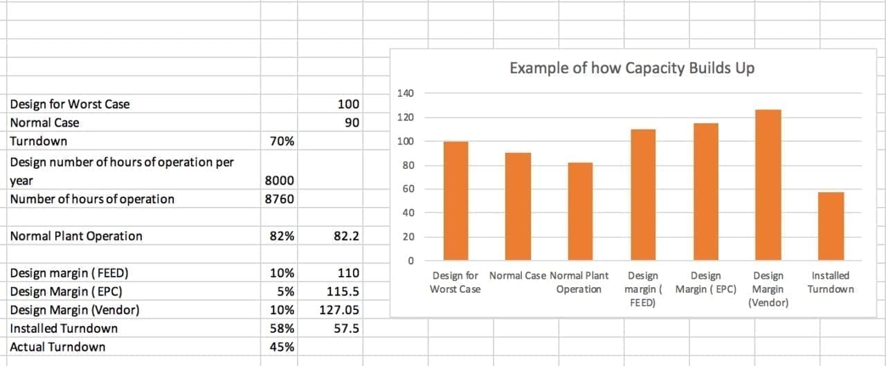
Figure 1. An example case illustrates how plants could get overdesigned
Without going further, the expected operation of the plant based on 8,760 h
( = 90% × 8,000/8,760 = 82%). And the stated turndown is 70% on 100% capacity, while the expected turndown is 63% (70% of 90%).
Let us say the FEED (front-end engineering and design) engineer then decides that the design margin on equipment is 10%, which is the standard company design practice.
So, now the FEED datasheet capacity is 110%.
The engineering, procurement and construction (EPC) engineer decides that, because the performance guarantee is for 110%, they should add another 5% to be safe. This margin is the responsibility of the EPC design engineer and the project management group.
So the IFD (integrated facility data) sheet states the capacity is 115.5%.
And the vendor, who needs to guarantee the equipment at 115.5%, is motivated to add in another 10%, just to be on the safe side. It is likely that the vendor will not make this addition obvious.
The vendor datasheet states the capacity at 115.5%, but the actual installed capacity is 127.05%
Remember from the initial information that when the plant runs on turndown, the realistic capacity needed is 63%. The capacity installed is 127%. The installed equipment is twice more than what is needed for the actual plant operating at turndown. Even at expected normal operation, the plant is designed for 127/82 = 1.55 times what is needed.
Challenges at turndown
Problems arise when there is a need to operate at turndown, typically during startups or periods of restricted feed or limited demand of product. The latter can be overcome by running the plant at full capacity and storing the product, if feasible. A restricted-feed scenario is more difficult to handle, especially if the feed is gaseous.
The following list guides engineers in ways to check the typical turndown of an individual piece of equipment to see where a “bottleneck” during turndown can arise.
- Compressors. Centrifugal compressors will have difficulty operating continuously below 70%, typically set by anti-surge considerations. Operating for a longer time below the surge point means that the equipment is continuously recycling, and if it is not designed properly for this condition, operations will be negatively affected. Reciprocating compressors can achieve a better turndown by unloading the cylinders. But even then, depending on construction, balancing the machine is important, which can limit the unloading
- Distillation towers. Distillation towers are relatively easier to work under turndown, provided one can avoid weeping by using valve trays or equivalent components. With sieve trays or packing, weeping and insufficient wetting are common problems. Using excess reflux is a way out of upsets caused by these issues, but that has a cost, in terms of cooling in the condenser and more steam in the reboiler.
- Centrifugal pumps. Centrifugal pumps also have a typical limit of around 30 to 50%, below which they will start to heat up. Recirculation is commonly provided to keep the pump above the minimum operating flow. Larger-horsepower pumps need to be designed carefully for this recirculation.
- Furnaces and process heaters. Furnaces and process heaters have a turndown of typically 3:1 to 6:1, although 10:1 is possible with special equipment, depending on the duty and the fluid being heated. Lower velocities in the tubes can lead to hot spots or coking. Lower fuel flowrates into the burner, especially low-NOx burners, affect emissions.
- Heat exchangers. Heat exchangers can react badly to low tube or shell velocities, depending on the fluid. Deposition of solids is very common if the velocities are low enough. It is important to note that when volumetric flowrate is halved, the velocity will be 0.7 times design.
- Boilers. Boilers will typically have a turndown of 2:1 or 3:1, principally because a lower turndown will imply the fluegases condensing in the stack. This can cause acid corrosion.
- Air coolers. Air coolers are particularly troublesome, especially in locations that have a wide temperature swing. If designed for summer conditions, the area available for heat transfer in winters is excessive. This may cause excessive condensation of the process fluids, which may have an adverse effect on plant operation. For example, if the temperature falls below the dewpoint of a gas being cooled, excessive liquid dropout in winters can lead to unnecessary tripping of the compressor.
- Turbines. Another interesting example comes from the power industry, where the GE Gas Turbine 7HA.03, touted as one the most efficient in its class, has a turndown of 30%, while meeting emission norms. This value looks good unless engineers think about the scale of the machine and look at the turndown from a different perspective. It is a 430-MW machine, which, under turndown, has a constraint to operate above 129 MW to meet emissions norms. The penalty for operating under turndown can frequently blindside the operator.
- Control valves. The controllability of the plant can be adversely affected if the control at low flowrates of a process stream is not sensitive enough. Lower flows also mean lower friction losses in a plant, and the pressure drop is a function of the volumetric flow of the fluid. The pump head rises with lower flow, and the valve then needs to kill a much larger pressure. Linear characteristics of a control valve can lose control at high pressure drop, when the valve opening is small. Note that the flowrate in a control valve is proportional to the square root of the pressure drop. A 10:1 turndown in flow can imply a 100:1 pressure drop control.
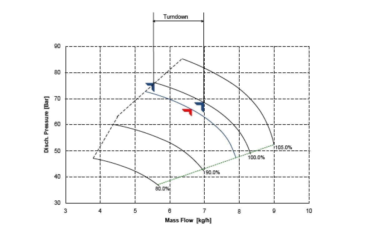
Figure 2. The figure illustrates turndown for a compressor
There are other types of equipment that can affect the effective turndown of the plant, and need to be evaluated carefully. Equipment in the critical flow path that cannot be turned down without significant penalties, can compromise the entire plant.
Sometimes the sheer nature of the process limits (or helps) the turndown. For instance, in a Claus desulfurization process plant, the acid gas flow at turndown can reach a point where one needs to co-fire natural gas to keep the temperatures in the range for reactions to occur. Due to improper design or operation, the flame can travel back and impinge on the burner, damaging it. A lower H2S composition can also be difficult for a plant, as one can push significant amounts of nitrogen or carbon dioxide gas through the plant, while heating the gases using natural gas, and producing limited sulfur.
Avoiding the turndown trap
Here are a few ideas on how to negotiate the turndown trap. The exact implementation of all the features of a well-designed plant needs a closer look by an experienced process engineer. Unfortunately, no amount of literature or design guides can protect against a poorly “over-designed” plant. Experience, which includes making mistakes and learning, is an essential ingredient for staying away from such pitfalls.
- First, evaluate the turndown requirements realistically. Specifying an extreme turndown can imply significant CAPEX and OPEX penalties. If the extreme turndown scenario is foreseen to happen for a limited time, there may be other more economic ways to handle it. For example, storing the feed for a limited time in a tank, and then processing it later, can be an option. A tank may be a better solution than engineering the full plant for an extreme turndown, which will happen for only a few days in a year. For example, a client demanding a 10:1 turndown requirement, despite the fact that this will happen infrequently.
- Start tracking design margins early in the project phase. Insist on complete visibility on design margins at every stage. A heat and mass balance for all compositions, and for all cases, including the turndown case, is important to track the margins.
- Ensure that the margins are explicitly spelled out in the datasheets. If a 10% design margin is selected for a particular equipment, then the data sheet should read 100 x 1.1 (units), rather than 110 (units). Especially easy to miss are the design margins hidden in notes. Typically, if a 10% margin on flow AND surface for a heat exchanger, it needs to spelled out in the individual column. The explanation can be given in the notes, but do not “hide” the margin quantity. Track the margins and the turndown for each equipment aggressively through to “as-built” data sheets. Ask the licensor, EPC contractor and the vendor for the effect of operating under turndown. For example, having a low velocity in the tubes of a heat exchanger can cause deposition. Have a good appreciation of the full consequences of operating under less than optimum conditions.
- Make sure the operator knows the margins and the full consequences of operating under turndown. This includes the penalty for operating under less than maximum efficiency conditions.
- If significant operations are anticipated under a smaller capacity (this can be easier said than done), having multiple trains is helpful. Brainstorm the scenarios before the datasheet for an equipment is released for purchase. The scenarios should include startup, shutdown and varying compositions. A consequence of more trains is invariably higher capital cost, but the benefit is higher availability.
- Provide “escape routes” during P&ID review. A provision to bypass equipment, such as a “tee” with a blind flange upstream and downstream of a piece of equipment, is useful in many situations. During a turndown scenario, sometimes an equipment, or even a plant, can be bypassed. A filter or a desalter can be bypassed during turndown. In a petroleum-refining facility, a “jumper” across the desalter is an inexpensive option for an “escape route” in case the basic sediment and water (BS&W) of the crude is acceptable without treatment during turndown. Look out for such opportunities during the design stage. Challenge the design for varying conditions of operations, including those demanding less duty from the plant.
To conclude, attention to turndown requirements is needed early in the project. Specifying realistic turndowns, keeping an eye on all design margins and specifying for conditions of such anticipated conditions will help in managing the turndown problematic scenarios effectively.
Author
 Rajiv Narang is the director of the Process Economics Program, at IHS Markit (London, U.K.; www.ihsmarkit.com) based out of New Delhi, India. He has worked over the last 30 years with various energy companies and consultancies. Narang has served as secretary and vice chairman of the Indian Institute of Chemical Engineers, Northern India Chapter. He is a senior member of the American Institute of Chemical Engineers (AIChE), a Chartered Engineer in the U.K., and a Fellow of the Institute of Chemical Engineers, (IChemE) in the U.K. He completed his undergraduate studies in chemical engineering at the Indian Institute of Technology in Delhi, and holds an MBA degree.