Temperature is among the most critical measurements in the chemical process industries (CPI) for operating safe and efficient processes. Because even a small error in temperature can lead to expensive consequences, accurate and reliable monitoring of temperature is required.
Thermowells
The most accurate temperature measurements occur when the sensor is in direct contact with the process fluid being measured. Since fluids in the CPI can often be corrosive or erosive, and can destroy a bare sensor quickly, the most common way of making temperature measurements is to use a thermowell. A thermowell is a hollow tube, often tapered, that projects into the process fluid to protect an immersed sensor. Because it is immersed in the fluid, the thermowell reaches the same temperature as the fluid.
Once a thermowell is installed, an immersion probe containing a temperature sensor is inserted into the thermowell from the outside so that the sensor fits flush against the end of the thermowell. Because the thermowell is immersed in the process fluid, it transfers the temperature of the fluid to the sensor. Thermowells can also be mounted onto the side of a tank.
Installing thermowells
The following are some general guidelines and tips for installing thermowells:
 |
Material of construction. A thermowell’s material of construction should be determined largely by the characteristics of the process fluid that flows past the thermowell, especially with regard to its corrosion properties, as well as its mechanical strength. The temperature and pressure ratings of all thermowells should be considered carefully when selecting to meet process demands. Common materials for thermowells include various grades of stainless steel, chrome-molybdenum steel, silicone bronze, Monel, Hastelloy B and C, nickel, titanium and others.
Type of connection. Thermowells are available generally with three types of connections — threaded, flanged and socket-welded.
Length of insertion. For best-possible accuracy, thermowells should be inserted into the pipe or vessel such that the entire temperature-sensitive part of the measuring element is projected into the medium being measured. For liquid measurement, the thermowell should allow the element to project into the medium at least one inch past the length of its temperature-sensitive area. For gases, the thermowell should allow the element to be immersed three or more inches beyond its sensitive length.
Bore size. For processes that are likely to use multiple types of temperature-measuring devices, the selection of a standard-sized bore diameter will allow the necessary flexibility.
Tapered or straight. Thermowells are available with either straight walls or a tapered shape. Tapered-shank wells can provide greater stiffness with the same sensitivity compared to straight-shank thermowells. Tapered wells have a higher strength-to-weight than straight ones, which gives rise to a higher natural frequency. This can come into play when considering the vibrational effects experienced by the process. Fluid flowing around a thermowell forms a turbulent wake that has a definite frequency based on the diameter of the thermowell. Any thermowell should have enough stiffness to ensure that the wake frequency never equals the natural frequency of the thermowell itself. If the two frequencies match, the thermowell could vibrate enough to break off inside a pipe.
 |
Further tips
• Thermowells can be used with pipes larger than 1.25-in. dia. In small pipe sizes, be sure the thermowell does not become an obstruction to flow
• Install the thermowell three to five pipe diameters away from elbows, flowmeters or other devices
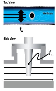
• Follow the thermowell manufacturer’s recommendations on pressure, temperature and fluid velocity. Thermowells can fail under certain conditions, including when under stress from wake-vortex-induced forces. These shedding vortices can lead to excessive vibration and potentially catastrophic failure when the vortex frequency approaches the thermowell’s natural frequency (Figure 1)
• Incorrectly designed and installed thermowells may fail at high flowrates. Once the wake vortex-induced force (at frequency fw) approaches the thermowell’s natural frequency (fn), catastrophic failure can occur unless correct thermowell calculations are performed
• For partially filled pipes, ensure that the bottom of the thermowell extends sufficiently into the process fluid
• For sizing and selecting thermowells, the American Society of Mechanical Engineers (ASME) Performance Test Code (PTC) 19.3 can be helpful. ASME PTC 19.3, which was rewritten in 2010, is a thermowell stress calculation that provides a mathematical indication that the material of construction and mechanical design of the thermowell will withstand the process conditions
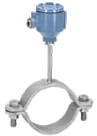
Immersed versus non-intrusive
In situations where thermowells are not feasible, engineers must consider non-intrusive temperature measurements (Figure 2).
While non-intrusive measurements are relatively easier to make than with a thermowell, and the apparatus is less expensive, surface measurements are not as accurate as immersion methods. Generally a surface measurement is accurate to within 1%, while immersion measurements can be accurate to within 0.1%.
Surface-based temperature-measurement devices should be insulated from the ambient temperature by wrapping the sensor connection and pipe with insulation. This helps avoid potentially false measurements.
References:
1. Omega Engineering, Introduction to Thermowells. Accessed from www.omega.com, Feb. 1, 2013.
2. Nguyen, K., Applying CPI Temperature Sensors, Chem. Eng., Sept. 2010, pp. 28–31.