A practical step-by-step guide for reducing future tube failure
Forced outage of a direct-fired heater is the worst nightmare for any operator in a petroleum-refining or petrochemical plant. Since fired heaters are not replaceable by spares, forced outage in many cases means emergency shutdown of the entire plant. In most cases, actual tube failure or even severe tube deterioration are responsible for outage of a direct-fired heater. Tube-deterioration mechanisms are not only an economical concern, but also a matter of safety of plant and personnel. An unpredicted tube rupture may lead to disastrous explosions and severe human casualties. In order to prevent such unwanted events and keep the fired heater tubes functional as long as possible, many petroleum refineries and petrochemical plants have organized a preventive program, which according to the American Petroleum Institute [1] is referred to as a “reliability program.”
Reliability programs
A good reliability program includes various detailed inspection programs performed both during heater operation and overhaul or occasional maintenance shutdown periods. Continuous assessments of the remaining lifetime of tubes and the supervision of heater performance are also included in the program of many refineries. Although reliability programs have proven successful during long periods of heater operation, many heaters are still victims of tube-deterioration mechanisms. That is because heater operators or field engineers are usually being kept out of the loop of a reliability program. It is true that deterioration mechanisms are mostly categorized as complex metallurgical phenomena, and inspection engineers with degrees or specialties in metallurgical engineering should evaluate and explicate them; but after the inspection or evaluation stage, the main root causes of such problems are mostly simple and can be explained to an operator with the aid of fact sheets or flowcharts. If the operators are being kept out of the loop, it is always possible for personnel to misinterpret a sign of tube deterioration. And since heater inspectors are not around all of the time, such misinterpretations could easily led to a disastrous event.
Dangers of misunderstandings
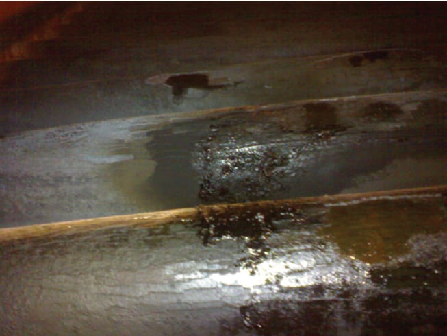
FIGURE 1. Misunderstanding problem signs led to a dramatic internal coke build up, followed by high tube metal temperatures, creep and finally tube rupture in one of the pass outlets of a visbreaker plant heater. Operators had unintentionally ignored high tube skin temperatures for one week
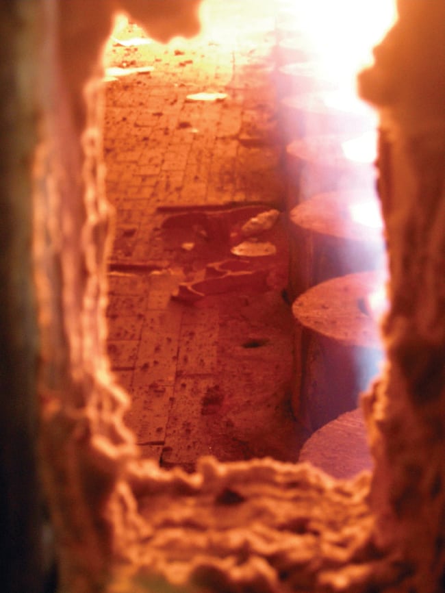
FIGURE 2. An example of good troubleshooting knowledge of operating personnel. Observation of a failed tube hanger triggered the alarm for possible roof tubes sagging and led to the heater shut down for maintenance and hanger repair
As an example, consider Figure 1, which demonstrates a dramatic tube rupture case that was the result of misunderstanding the problem signs and lack of root-causes knowledge of operating personnel. In this particular case, the pass outlet was near the internal header-box refractory linings. Because of this, the operators had unintentionally ignored high tube-skin temperatures and assumed that they were misreading the refractory wall temperature by the infra-red pyrometer. If they were aware of other signs and root causes of internal coke build up (fouling), such as back pressure in the specified pass, maybe serious course of actions would have been considered before raising the tube metal temperature to values that had eventually caused severe creep and tube rupture. Explaining the root causes of the deterioration mechanisms to the operating team can prevent deterioration in the first place. It is important that the inspection team arrange meetings in which operating personnel take a walkthrough the chain of events and performance imbalances that lead to a tube failure. As another example, the situation shown in Figure 2 was dealt with before the shield section tubes experienced serious sagging, which could easily lead to tube rupture and possible explosion. As the operators were aware of the possible threat of roof tubes sagging (in case of fallen or failed tube hangers), observing the failed hanger at the floor of the heater triggered an alarm, which led to the shutdown of the heater for maintenance and hanger repair. A good troubleshooting guide can demonstrate the fact that failed roof hangers are caused by overheating in the convection section. In this vain, by monitoring burner flame heights and burner fuel pressures (controlling the amount of heat released), as well as monitoring bridge wall temperature, operators can prevent this phenomena in the first place.
Troubleshooting
Even if a company follows proper training courses for personnel, and has an effective reliability program and an effective schedule of visual inspections, these measures will not reduce the importance of practical troubleshooting knowledge. An operator without proper knowledge and understanding of root causes and a troubleshooting sequence would ignore or misunderstand vital signs of a possible tube deterioration mechanism. In this article we have proposed a simple root-cause analysis and also a computerized troubleshooting algorithm that directs the heater operator from one root cause of a possible tube-deterioration mechanism to another, in sequence, indicating how each of the improper performances for a given cause is to be corrected, and continues in this vain until all possible causes for tube-deterioration mechanism can be corrected.
Tube-deterioration mechanisms
According to the valuable references listed at the end of this article [1, 3–4], as well as our field experience, typical fired-heater tube-deterioration mechanisms that may lead to tube failure can be classified into the following 12 main categories:
- Local or longitudinal hotspots
- Internal fouling
- External fouling
- Internal corrosion
- Creep (general or minor creep)
- Bulging
- Bowing and sagging
- Vibration
- External dew point corrosion
- Erosion
- Thermal fatigue
- Mechanical deterioration
Root-cause analysis
It should be noted that before entering the root-cause-analysis phase, one should not neglect the possibility that the material of construction used for the heater tube can be a possible cause of some of the problems referred to above. Thus, readily available data for allowable stress and corrosion rates for various tube alloys, as a function of temperature, should be made available from appropriate tube manufacturers. These data should be checked before taking any step for understanding the root causes of tube-deterioration mechanisms. In order to analyze each deterioration-mechanism category and its sub categories in the most concise and efficient way, a root-cause-analysis table has been proposed (see Table 1). By understanding the root causes of tube-deterioration mechanisms, one has passed through the primary step of tube damages troubleshooting. Now what matters the most is the proper sequence of troubleshooting actions, which are provided by comprehensive algorithms described in the next section.
Troubleshooting algorithms
The comprehensive troubleshooting algorithm referred to above is based on the logic depicted in Figures 3 to 14, and has been successfully used to both recognize what the tube-deterioration mechanism might be, indicate the cause of the problem and correct the heater defect, so as to achieve the proper tube operating lifetime.
A practical example
Let’s assume that an operating team tries to prevent a future tube failure like the one shown in Figure 1. In order to achieve this goal, it is obvious that they need to troubleshoot the deterioration mechanisms that are responsible for this event. First of all, an inspection team should identify the nature of tube-deterioration mechanisms that have led to such a disaster. A preliminary analysis would demonstrate that severe tube creep accompanied by internal fouling (coke build up) are to be blamed. This particular heater is in visbreaker service, which can be classified as a thermal cracking process. In thermal cracking of heavy petroleum cuts, coke formation is an unwanted side reaction that cannot be eliminated, but the reaction rate and duration can be controlled and reduced by maintaining proper operating conditions. In some cases the interval between decoking processes can be extended by up to three to four years. 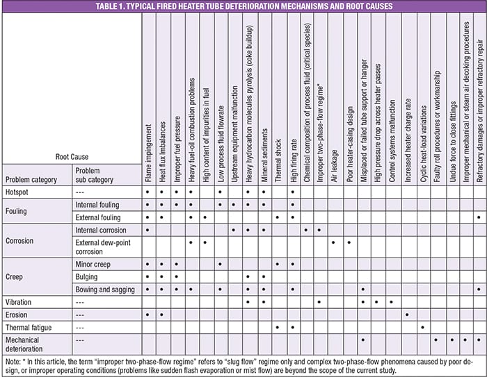 In this particular case, unwanted coke deposition had happened during the first year of an operating period. This event was unpredicted and surprising for the operators. Internal fouling, caused by rapid local coke formation, made an insulating layer, which in turn led to higher tube skin temperatures for long periods of time. In this vain, high tube-skin temperature led to sever creep and eventually disastrous tube rupture. In order to solve this problem and prevent it from ever happening again, the main cause that is internal fouling should be clearly understood and analyzed. By taking a look at Table 1, one can find the root causes of internal fouling, which are as follows (not necessarily in order of priority):
- Flame impingement
- Heat flux imbalances
- Improper fuel pressure
- Heavy fuel-oil combustion problems
- Low process fluid flowrate
- Upstream malfunction of equipment
- Pyrolysis of heavy hydrocarbon molecules (coke buildup)
- Mineral sediments
- High firing rate
With the exception (in some cases) of root-cause Number 9 (high firing rate) [2], all the other causes can be treated by the stepwise troubleshooting procedure outlined in this article. In order to solve the internal fouling problem, the operator can start with the procedure given in Figure 4. This procedure starts with the simplest solution, which is solving low process-fluid flowrate in heater passes. Low process-fluid flowrate can cause high tube-skin temperatures that can lead to internal fouling. It should be noted that human error and control equipment malfunction are the main causes of low process-fluid flowrate. It is mandatory to prepare a regular program for checking control equipment accuracy. Also, restrain inexperienced personnel from controlling sensitive equipment like fired heaters.
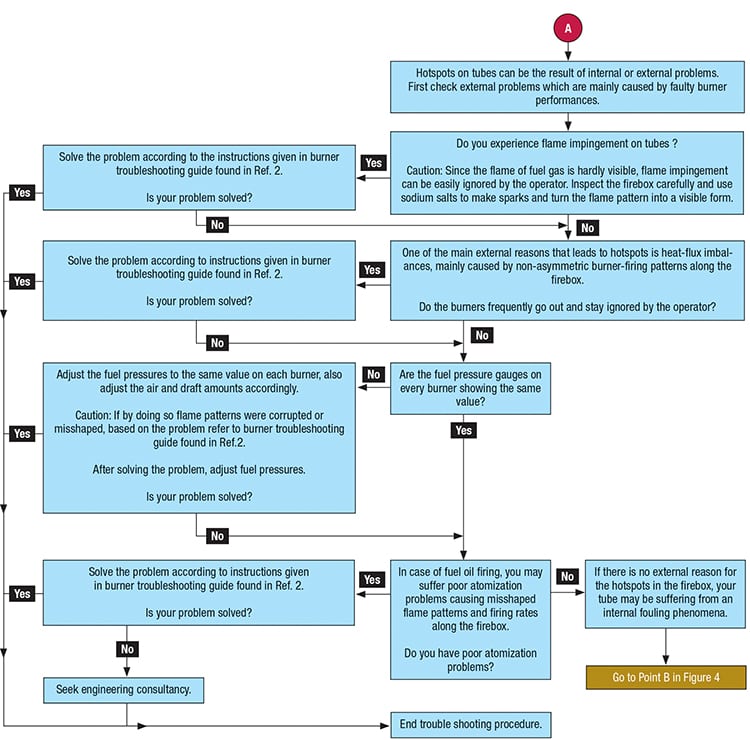
FIGURE 3. Troubleshooting algorithm for hotspots on the tubes
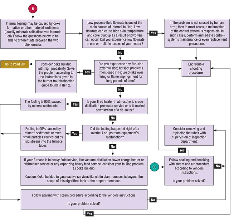
FIGURE 4. Troubleshooting algorithm for internal fouling
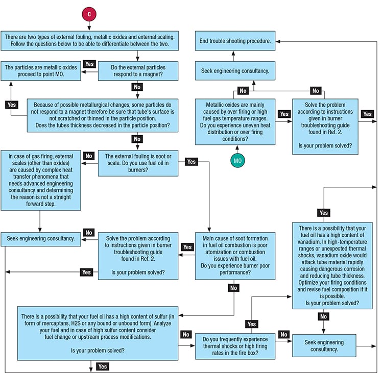
FIGURE 5. Troubleshooting algorithm for external fouling
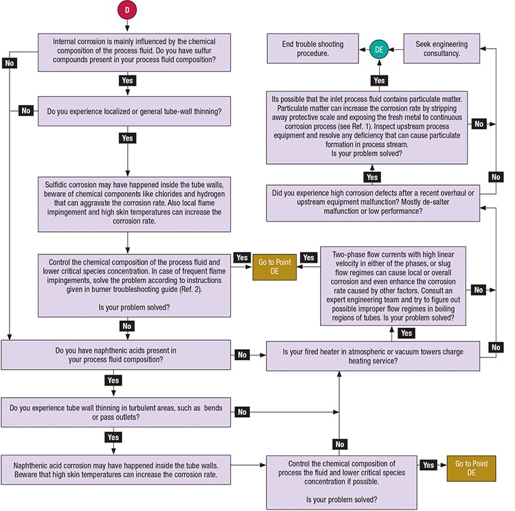
FIGURE 6. Troubleshooting algorithm for internal corrosion
If the problem is not related to this cause, the operator is asked to check for burner firing problems, like flame impingement, heat-flux imbalances, improper fuel-oil pressure or heavy fuel-oil combustion problems. If any of these problems have been observed for long operating periods, one can almost be certain that the internal fouling is due to coke buildup. In order to solve any burner-firing problem, the operator can refer to the detailed troubleshooting algorithms described in Ref. 2. Mineral sediments fouling, which is not the case in this example, may happen in crude charge heaters that are placed after de-salters and heat exchanger networks in most refineries. Apparently, if the heater is in crude charge service, checking the de-salter’s malfunction should be the next step in the trouble shooting algorithm. If this is not the case, upstream equipment malfunction can be the next cause. Small particles carried by a fluid stream can plug heater tubes and reduce flowrate locally or in a whole pass. Similar to low process-fluid flowrate, this can lead to severe internal fouling. Operators should be warned about the possibility of this problem, specifically after overhaul or upstream equipment malfunction and maintenance. As the next step, the nature of the process should be noted. For visbreakers or any service in which heavy feed is vaporizing, coke buildup is a certain possibility. As coke formation in these kinds of heaters is highly anticipated, controlling operating conditions, especially the items mentioned in previous steps of this algorithm, is very important and vital. By following the right steps, operators may control — and even in some cases eliminate — coke buildup phenomena. Other steps of this algorithm are dedicated to the decoking and spalling practices that should be followed, depending on the nature of the internal fouling problem. Following this procedure would usually eliminate and even prevent future internal-fouling problems, as for the case history shown in Figure 1. Surveying the operating history of the heater proved that long-time local flame impingement was the main cause of this event, and tuning the draft and excess-air amounts could have solved the problem in the first place. As a final note, we should add that our experiences have proven that in similar case histories, increasing the awareness and knowledge of operating teams about the initial signs of internal fouling phenomena is as important as knowing the troubleshooting sequences. For example, in a similar case that happened in a vacuum charge heater, operators were too much dependent on infra-red pyrometer measurements of tube-skin temperatures. That misreading of the skin temperature made them ignorant to the actual problem that was taking place. As depicted in Figure 15, the process fluid flowrate had decreased during coke buildup and simultaneously, the heater pass inlet pressure increased 80 psig. These two events are very obvious early warnings of internal fouling in the specified heater pass (Pass A of Figure 15). The operators had simply related the decreased flowrate to the control equipment malfunction and ignored it. If the operators were aware of other warning signs of possible internal fouling, this problem may not have endured for such a long operating period that would led to tube rupture. This is another reason for the necessity of an operator-involved reliability program in refineries in addition to good troubleshooting knowledge and training. 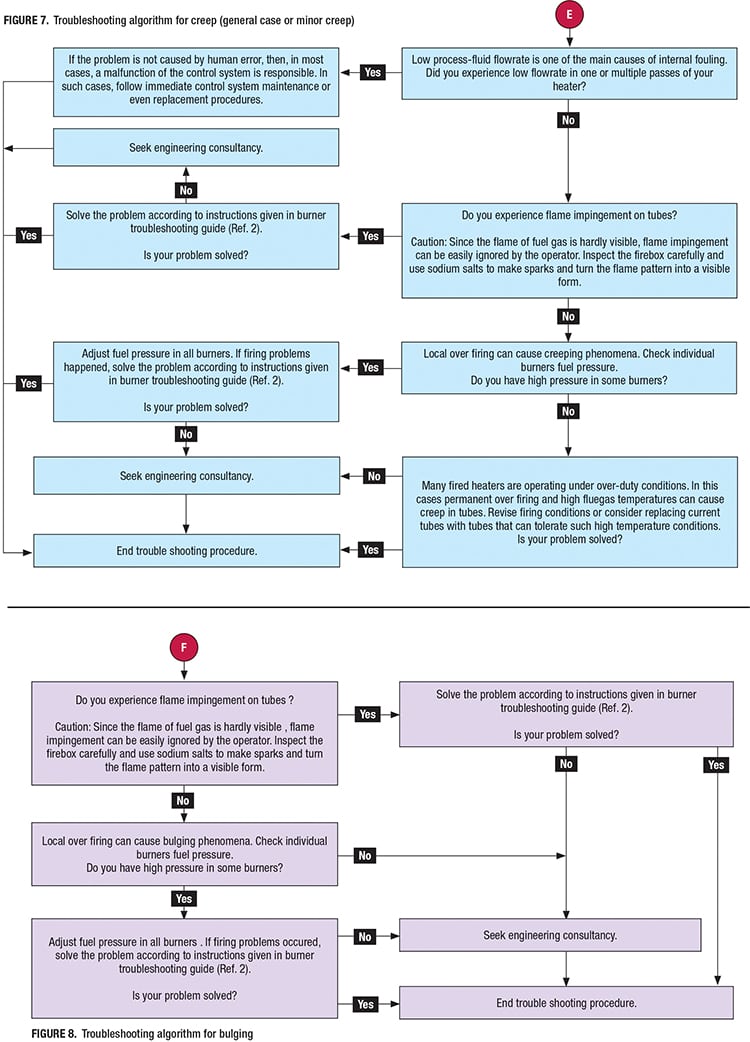
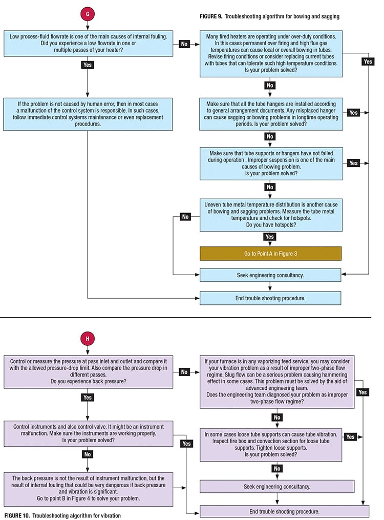
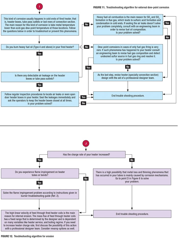
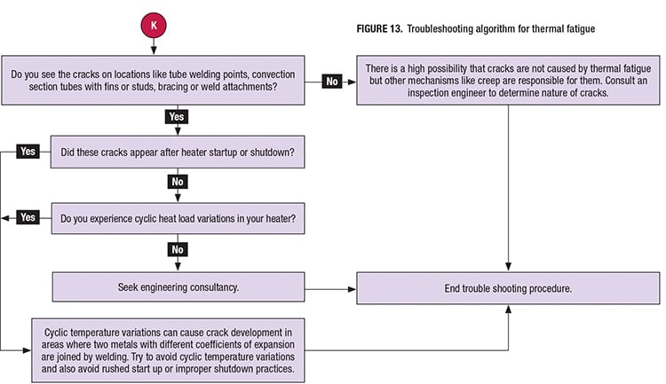
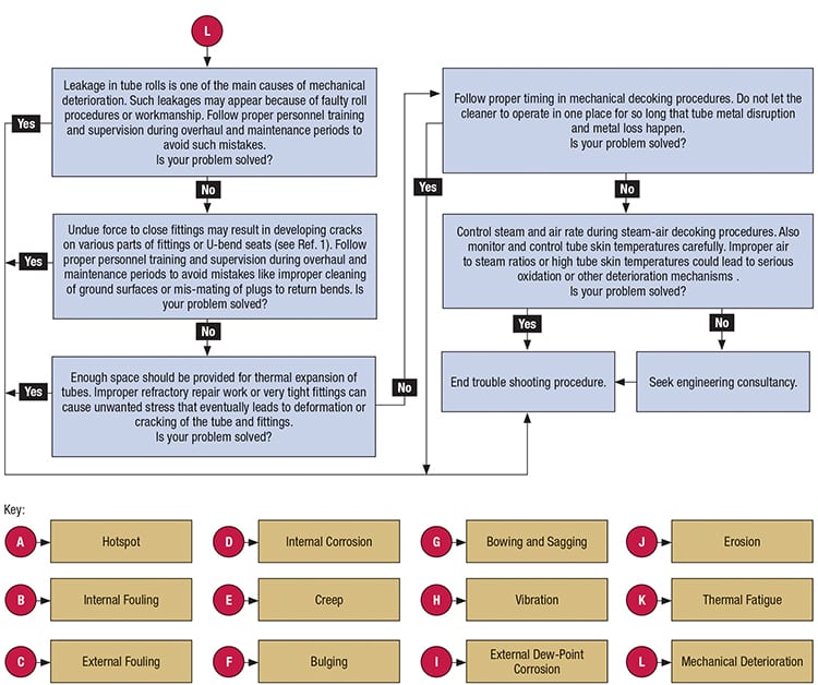
FIGURE 14. Troubleshooting algorithm for mechanical deterioration
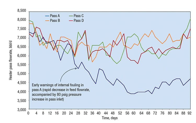
FIGURE 15. This graph shows the operating history of the process fluid flowrate in four passes of a vacuum distillation unit charge heater. Ignoring early signs of internal fouling caused by rapid coke build up, led to disastrous tube rapture, like the one depicted in Figure 1
Computerized algorithm
A computer program (computer wizard) can easily be developed based on logic described in Figures 3 to 14. By using this program in industrial environments, like petroleum refineries and petrochemical plants, operators will be able to understand and correct the root causes of a possible deterioration mechanism in more efficient ways. As result less maintenance operations or mandatory tube replacements will be needed. It should not be forgotten that the main cost saving and also safety benefits of this program will resulting from the following:
- Fewer forced direct fired heater outage events due to tube failure
- Elimination of disastrous events, such as a heater explosion caused by unpredicted tube ruptures
- Extending the operating lifetime of heater tubes
- The possibility of increasing throughput and decreased down time for decoking operations
Edited by Gerald Ondrey
Acknowledgment
The authors wish to thank the help and contribution of Alan Cross. He is always a mentor to us whom gives us the courage and motivation for preparing and submitting our experiences in engineering papers.
References
- American Petroleum Institute, “Inspection of Fired Boilers and Heaters,” Recommended Practice No. 573, API, Washington, D.C., Feb. 2003.
- Maghbooli B., Najafi H., Bakhtiari A., Correcting Improper Performance of Direct Fired Heaters: A practical, step-by-step approach for finding the root cause and troubleshooting burner problems, Chem. Eng., May 2013, pp. 39–46.
- American Petroleum Institute, “Damage Mechanisms Affecting Fixed Equipment in the Refining Industry,” Recommended Practice No. 571, API, Washington, D.C., April 2011.
- Patel S., Typical Fired Heater Problems and Root Causes, Hydrocarbon Process., March 2007, pp.68–69.
Authors
 Babak Maghbooli is a member of the research and development team of Farayand Sabz Engineering Co. (No.117, Somaye Street, Tehran, Iran; Email:maghbooli@xthermo.com). With more than six years of experience in the field of tuning process fired heaters and troubleshooting their problems, he has provided consultancy services for more than five petroleum refineries in the field of troubleshooting, maintenance and analyzing mechanical and thermal behavior of fired heaters and boilers. He also has practical and professional experience in the field of process simulation and developing root cause analysis procedures for chemical process problems. He is an advanced VBA programmer and has developed many process simulation solutions in MS-Excel for various consulting projects. He holds a B.Sc.Ch.E. degree from Arak University and He is an associate member of IAChE and CSChE.

Hamidreza Najafi is head of the research and development team of Farayand Sabz Engineering Co. (same address as above; Email:hrnajafi@xthermo.com). He is a professional object oriented programmer and his main interest is developing simulator packages for industrial processes. With more than 12 years of experience, he has practical and professional experience in the fields of thermal radiation especially for design and simulation of thermal cracking furnaces and process fired heaters and also development of chemical kinetics and thermodynamics framework for simulator software. He has provided numerous solutions for process problems in these fields for various oil and petrochemical companies. He has a B.Sc.Ch.E. degree from Sharif University of Technology and a M.Sc.Ch.E. degree from Shiraz University and He is an associate member of IAChE and CSChE.