Waterhammer arises because of sudden changes in fluid flow, and can present significant problems in processes that involve flowing liquids. This article outlines these potential issues and offers guidance for handling the pressure changes arising from waterhammer
Most large-scale processes in the chemical process industries (CPI) are designed to run at steady state. Even if a process is a batch operation overall, it usually includes at least some continuous segments. When fluid flows are constant, process operation is efficient, cost-effective and safe, and effects are predictable. However, when fluid flows change (whether the change was intentional or not), a wide range of consequences can result, and they are often difficult to fully comprehend and predict. The effects from changing fluid flow are collectively classified as “waterhammer.” This term has also been used in the context of home plumbing systems, where waterhammer can generate noise from otherwise silent pipes. However, waterhammer in home plumbing represents only a small-scale example of what can be very serious topic at industrial scales (Figure 1).
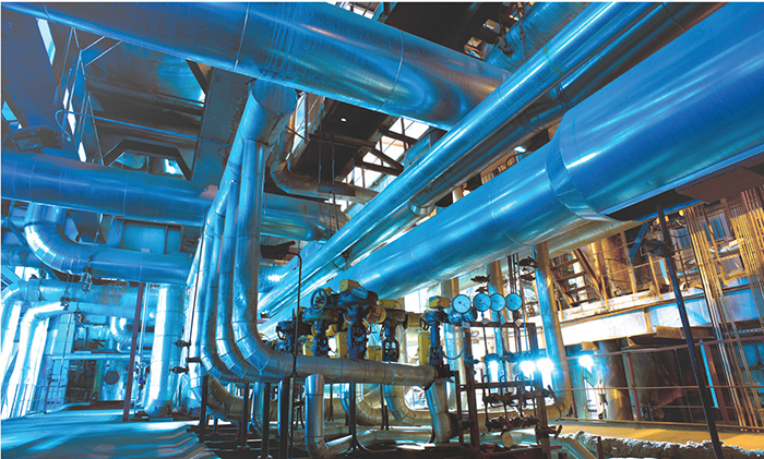
Figure 1. Changes in fluid flows within industrial piping systems can cause waterhammer, which can result in a wide range of consequences
Waterhammer is the phenomenon of pressure-wave propagation that follows a change in fluid flow — usually in the context of a sudden change. It is most common to associate these changes with a valve closure of some sort. Liquid systems running at steady state have large amounts of momentum. In a situation where the momentum of flowing liquid is stopped suddenly, the forward kinetic energy is converted to potential energy, in the form of pressure. Controlling this pressure rise is a salient concern for industrial processes.
As flowing liquid comes to a stop throughout the rest of the pipes, the resulting pressure wave propagates, similar to a sound wave in air. A logical line of consequences follow: moving flow stops, rising pressure results, propagating pressure waves march forth. Propagating pressure waves can cause damage to pumps, to pipe components, and to the pipe itself. As a result, standards and codes have existed for some time to guide engineers toward a safer design.
High-pressure considerations
The American Society of Mechanical Engineers (ASME; New York, N.Y.; www.asme.org) standard B31.4 (Pipeline Transportation Systems for Liquids and Slurries) states that protective equipment must be in place to ensure that any pressure surge does not exceed 10% above the internal design (steady-state) pressure. This stipulation provides a baseline for system design. The process engineer’s job then is to analyze those situations and locations within the process where flow can potentially change, such as pumps and valves, and make sure that mitigation equipment is sized properly, according to the possible changing-flow scenarios.
Most engineers will run calculations on the worst-case scenario, often assuming that a valve closure is instantaneous. These calculations will yield an expectedly conservative pressure rise, and engineers can then design the protective equipment, such as bladders or relief valves, to control the surge and meet the requirements of the design code. The standard formula for maximum pressure surge is the Joukowsky equation, as shown in Equation (1).
∆P= –ρa∆v (1)
In the equation, ∆P is the instantaneous change in pressure, ρ is the fluid density, a is the wave speed (a function of the fluid and pipe properties), and ∆v is the instantaneous change in velocity. This equation is valid as long as the implications and assumptions are well understood. Figure 2 shows a pressure surge from a fast valve closure.
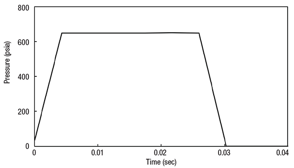
Figure 2. The graph depicts a pressure surge following a rapid valve closure in a pipeline
The Joukowsky equation describes the pressure rise from an instantaneous change in velocity. That pressure rise will represent the worst-case scenario for components near that valve for the initial pressure wave. But this initial surge will result in secondary effects when waves do what waves do, which is to propagate, reflect and interfere with one another. In long pipelines, there is also line pack (frictional pressure-loss recovery) to consider. Often, these later effects can result in worse conditions than those arising from the initial surge. Predicting these secondary effects by hand is a tall order, but software for waterhammer analysis is available and can be helpful.
Low-pressure considerations
One of the major (and often unanticipated) effects of waterhammer is low pressure. It is not the obvious concern, and it is not easily predicted. As mentioned previously, design codes are available for allowable overpressure, but there is not a single code for allowable underpresssure. Engineers are left without guidance in that regard. Many engineers unknowingly consider only half of a pressure wave’s effects.
There are many different events that can cause low-pressure waves. One of the more intuitive examples is something like a pump shutdown. As a pump shuts down, pressure is no longer supplied to the fluid, but the fluid still moves forward. This leaves a low-pressure zone that eventually catches up to the rest of the line as it finds mechanical equilibrium.
However, low-pressure effects also arise as part of the wave cycle from the traditional valve closure discussed above. The high-pressure wave travels through the pipe until it meets a point of reflection. When that wave travels back toward the originating valve, it reflects again with a low-pressure wave. This is the second half of the “wave cycle.”
Although hard to visualize, the wave cycle follows a momentum balance of velocity and pressure. Without introducing too much detail, velocity also changes as the pressure wave cycles. When the wave reflects off the originating valve, the fluid changes from negative velocity to zero velocity. This “increase” in velocity is met with a decrease in pressure, below the steady-state value. A low-pressure wave will always follow a high-pressure wave. The severity of the low-pressure wave depends on dampening from friction and mitigation efforts.
Another case of low-pressure concern in waterhammer is the area immediately downstream of the closed valve. Similar to the pump trip, there is no momentum transfer to the downstream fluid once that valve has closed, but the fluid still has inertia driving it forward until the system corrects toward equilibrium. This creates a low-pressure area and disturbs the line’s pressure balance.
Whatever the cause of low-pressure waves, they are frequently not considered in a transient analysis. Thinking intuitively, one might imagine that the low-pressure situation cannot be nearly as bad as the high-pressure effects. It is common to associate high-pressure scenarios with higher overall pipe stress and lower-pressure occurences with less pipe stress. While that thinking is somewhat true, there are other factors for which to account.
Vapor formation
If the negative-pressure wave drops the line pressure below the vapor pressure of the fluid, the fluid will flash (partially evaporate) and form a short-lived vapor pocket. When the pocket is large enough to form a clear boundary between the upstream and downstream liquid, the situation is referred to as “liquid column separation.” This term is also used more generally to describe any liquid flashing.
Formation of vapor pockets inside a pipe can create a situation that is worse than the initial high pressure. Pipes tend to resist internal high pressure much better than they resist internal low pressure. Often, vapor pockets create vacuum conditions where the ambient pressure is much higher than the internal pressure. This pressure differential can actually be more strenuous on a pipe than if the pressures were reversed (higher pressure inside the pipe than outside the pipe). These pressure differences due to these vacuum conditions may cause pipe collapse and harm the integrity of the pipe wall.
Even if the pipe does not collapse, the vapor pocket will. The collapse causes yet another high-pressure wave to burst forth. These resulting pressures can be even larger than the original pressure wave from the valve closure. The vapor pocket collapses with so much power that it often bursts nearby pipe joints. The concept is very similar to pump cavitation. The collapse of the tiny vapor bubbles happens with enough force to cause “pitting” and damage to the impellers. The same thing happens with liquid column separation, but on a larger scale. Figure 3 shows the vapor collapse behavior downstream of the same fast valve closure shown in Figure 2. Compare the resulting pressures here with the initial pressure seen in Figure 3. The large pressure from vapor pocket collapse is not predicted by conventional calculations.
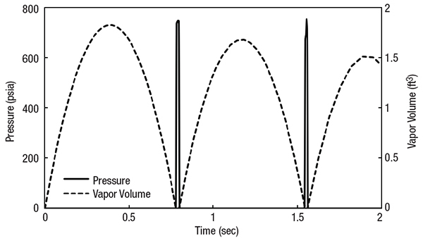
Figure 3. After a rapid valve closure, such as the one represented in Figure 2, the pipe can experience a vapor-collapse scenario, as shown here in graphical form
Stress on a pipe and its components due to vacuum conditions and vapor collapse may not be the most critical concern. In many situations, such as wastewater treatment or food processing, the process itself is the concern. Even mild vacuum conditions can pull outside contaminants into the pipes. Joints are the main concern here, because the seals and gaskets will be the areas where those contaminants come through if a vacuum is present inside the pipe. Engineers working with aseptic processes especially need to be vigilant for these conditions.
Transient event mitigation
Hopefully, the prior sections of this article have made it evident that waterhammer is a serious and complex issue. From a single transient event, a wide range of damaging conditions can arise. So the question now becomes how to mitigate the effects of waterhammer. While the instigating events may be unavoidable, engineers can design countermeasures to account for the effects of waterhammer and maintain compliance with the ASME code.
A common way to mitigate waterhammer is to manage the initiating event itself, if possible. The simplest solution is to close the valve over a longer period. The previously mentioned Joukowsky equation predicts the pressure rise from an instantaneous change in flow. If that change in flow is spread over a longer time, then the resulting pressure wave is less extreme. The longer the time interval for fluid-velocity change, the lower the magnitude of acceleration, and the lower the resulting force and pressure.
Like most of life, the reality is more complicated. Each type of valve has unique characteristics, and the exact timing of how to close the valve depends on those characteristics. The suggestion for valve closure mainly relies on how the Cv (flow coefficient) changes with valve position, and then how that valve position changes over time. If Cv (and thus, flow) changes dramatically near the end of valve closure, it is very important to close it slowly during that period.
There is a common valve closure practice known as the “80/20 rule.” That is, take 20% of the total valve-closure time to close the first 80% of the valve, and then take the last 80% of the time to close the final 20% of the valve. Closing the valve more slowly toward the end mitigates the surge because this is usually the moment of largest velocity change.
However, even this rule of thumb has its limitations. If the valve has a large pressure drop relative to the pressure drop of the entire system, then this valve may already have tight control of the flow. Changing the valve position affects the system’s flow significantly. In this case, the valve should be closed very slowly throughout the entire closure, because every change in position is significant. Understanding your valves and their interaction with the system is important, but difficult. Software for waterhammer analysis can be helpful in this regard as well.
Surge suppression equipment
Slowing valve closures as a waterhammer-mitigation method require a planned closure. But of course, an unplanned need to close a valve can also occur, leading to unexpected transient flow events. For instance, a power outage may cause a pump trip, which then causes a check valve slam (rapid closure). In cases like these, in-line equipment is required to mitigate the waterhammer.
Relief valves or rupture disks are common in-line components, because they are a logical resolution to high-pressure situations. Similar to a crumple zone in a car, relief components take the load on themselves. They pop open when pressures become too high, easing the effects on other parts of the process. Unfortunately, rupture disks and relief valves are not all-encompassing solutions, because they are sized for certain pressure scenarios that are not always easily predictable.
Vacuum-breaker valves are another mitigation strategy with the opposite motive of relief valves. For the low-pressure situations discussed earlier, the vacuum-breaker valves break the vacuum that can accompany a low-pressure condition (where the pipeline pressure is below ambient pressure). Vacuum-breaker valves allow air into the system to relieve the low pressure.
That same breaker valve may also have a way for the air to escape when the pressure bounces back. With these multi-stage valves, the exit rate is very important to control. If the air leaves too quickly, the fluid columns may slam together, causing yet another surge event. While breaker valves are effective, they may not be practical if a process is sensitive to contamination or oxidation. An inherent limitation of single-stage breaker valves is that the trapped air will cause a decreased area for liquid flow, and thus, will increase the fluid’s velocity. Additionally, the entrained air can negatively affect pumps and other components.
In addition to valves designed to relieve either high or low pressures, there are surge vessels that mitigate both extremes. Surge vessels come in many styles, but they are essentially in-line vessels that provide both a refuge and supply for process fluid during a transient waterhammer event. Two standard styles are open and closed vessels. Open vessels are also known as “standpipes,” and are useful when contamination is of little concern. Closed vessels are charged with an inert gas to control the compression and expansion (Figure 4).
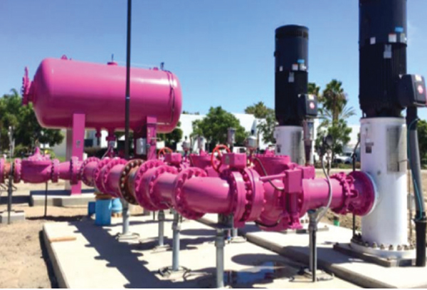
Figure 4. Closed surge vessels filled with inert gases, such as the one shown here, can be used as waterhammer-mitigation devices
When surge pressures arise, the vessels absorb the energy from the pressure spike, acting as an energy sink. When the low-pressure part of the wave cycle comes through, the vessels become an energy source, providing the necessary fluid and pressure. In this way, they act like both relief and vacuum-breaker valves, but they are much more versatile. Closed vessels act for both the high and low pressures, while open vessels are typically designed for protection from low-pressure situations. The nature of open vessels requires excessively tall walls if the vessel is intended to absorb a high-pressure surge. However, this is not unheard of.
Waterhammer analysis software
The ability to predict the placement of waterhammer-mitigation components is no easy task. The design of the mitigation components themselves also requires the pressure predictions discussed earlier. Incorrect placement of this equipment can make the situation even worse, through resonance or re-triggering the surge. But most engineers work in aging plants, so they inherit the system of the original designers. Plants usually have relief valves or vessels distributed throughout. For plants designed decades ago, without modeling software, introducing relief valves and surge vessels was a common practice to protect against unpredictable surges.
Without software to analyze wave behavior, process design becomes a rough estimate in an effort to meet the requirements of the code. Modern modeling methods allow engineers to better predict waterhammer events and the effectiveness of mitigation efforts. Targeted pressure control makes processes safer and more efficient overall. But more robust mitigation efforts require more robust technology for guidance. Being able to predict the unanticipated low pressures, column separation and subsequent high-pressure waves requires more time and calculation than most engineers are willing and able to invest. After all, the system is probably designed for steady-state conditions.
Waterhammer analysis software can take the pressure off engineers by modeling the transient events, predicting expected behavior at various conditions, and evaluating the effectiveness of suppression methods. Even today, waterhammer analysis is not always part of the standard design process. Using the initially assumed worst-case scenario is often where the analysis starts and stops. Instead, take waterhammer analysis beyond the standard methods, and consider all the complex consequences of a change in flow.
Edited by Scott Jenkins
Author
 Walt Prentice is a business applications engineer at Applied Flow Technology (AFT; Address: 2955 Professional Place, Suite 301, Colorado Springs, CO 80904; Phone: 719-686-1000; Email: waltprentice@aft.com). Prentice holds a bachelor of science degree in chemical engineering, with a minor in economics, from the Colorado School of Mines in Golden, Colo. As a business applications engineer at AFT, he supports engineers around the world in troubleshooting piping and ducting models.