Information provided here can help guide the selection of valve actuators that are best suited to the demands of a particular chemical processing application
Actuators are machines used to control the position of a valve remotely and automatically. They are attached to the control mechanism of a valve to replace the manual lever or handle. Valve actuators are essential components in flow-control systems. The primary function of an actuator is to control the position of a valve. The actuator can close a valve, open a valve, move a valve to a specific position, hold the valve in place, prevent valve leakage by creating a tight shut-off, operate in failure mode, modulate flow through a valve and so on.
In industrial applications, numerous types of actuators are available, and they can be connected to a variety of valve types. Selecting the proper actuator for a given application is a task that must be considered seriously. Several factors influence the kind of actuator that is suitable for a process. This article is an all-in-one actuator guide that covers the essential function of actuators, outlines actuator types, and describes important considerations for valve-actuator selection for the particulars of an application.
Actuator operations
Actuators control valves through three standard valve operations: quarter-turn operation, multi-turn operation and linear operation.
The quarter-turn operation involves valves that rotate 90 deg from the closed position to the open position (for example, ball valves and butterfly valves). The actuator control on quarter-turn valves can be on/off or modulated. Actuators for these valve operations are usually easy to install and maintain.
On the other hand, multi-turn valve operation requires the actuator to turn the valve mechanism several rotations before moving the valve from the opened position to the closed position. The mechanism can be a rising non-rotating stem or a non-rising rotating stem. Examples of valve types with this operation include globe valves, gate valves and needle valves.
Some valves are opened and closed through the linear operation of the valve mechanism. Linear operation involves motion in a straight line (in contrast to the circular motion of quarter-turn and multi-turn valve operation, although some multi-turn valve operations have the same mechanism as a linear valve operation — for example, certain types of globe or sliding gate valves). Linear valve operation can be driven in a number of ways other than by an electric motor. Linear motion can also be achieved by mechanical, hydraulic, pneumatic or piezoelectric power sources.
Types of valve actuators
Two main types of actuators, based on their motion, are linear and rotary. However, actuators are generally defined by the source of power that drives the actuator. They can be sorted as the following:
1. Electric actuators (powered by electricity; Figure 1)
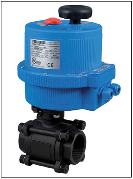
FIGURE 1. The photo shows an electric actuator mounted to a carbon-steel three-way ball valve
2. Pneumatic actuators (powered by pressurized air; Figure 2)
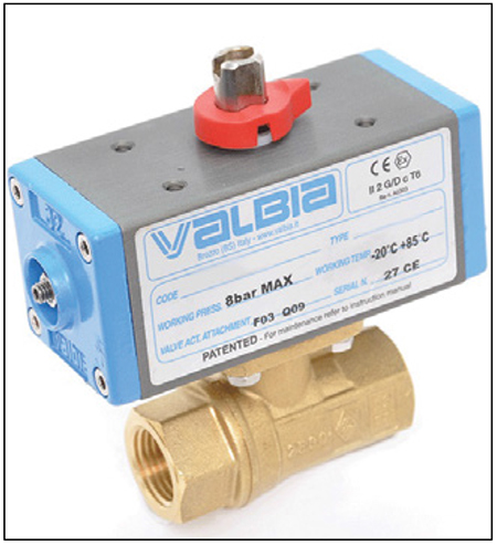
FIGURE 2. The pneumatic actuator shown here is attached to a two-way ball valve made of brass
3. Hydraulic actuators (powered by fluid; either water or oil)
Electric actuator. Electric actuators use electrical energy — usually 24V, 110V, 230V, 400V, single- or three-phase, to drive an electric motor whose rotor is connected to the shaft/stem mechanism of the valve. The electric motor can be powered by alternating current or direct current. They are an energy-efficient, clean and quiet method of valve control. The electric motor may be connected to the valve mechanism through gears to increase torque or regulate speed. Electric actuators are available for both very small-sized applications, as well as for actuators on large valves in industrial applications.
Electric actuators are capable of relatively high speeds if needed, but they tend to be slow-reacting if standard-specification actuators are used. There is an option to install a positioner that converts an on/off actuator to a modulating actuator capable of precise flow control. However, if electric actuators are modulating constantly, the motors can burn out. Electric actuators often have a declutching mechanism to allow rotation of the drive during a power failure or installation. Emergency power can be provided through a battery to ensure a fail-safe operation.
A specific category of electric actuators is called linear actuators. They also convert electric energy from an electric motor to mechanical motion. However, the motion is not rotational to turn a valve, but to move a stem attached to a load or a valve in a linear direction. They are used in globe and gate valves and many other functions requiring linear motion of a load.
Pneumatic actuator. Pneumatic actuators are highly reliable actuators that are popular in industrial applications. They convert compressed-air energy into mechanical motion and can be used in locations with no electricity. Pneumatic actuators are of two types: single-acting or double-acting. Single-acting pneumatic actuators use a single compressed-air source to turn the valve with a spring to return the valve to the normal position. A double-acting pneumatic actuator has two compressed-air sources that turn the valve and return it to the original position, otherwise known as a fail position.
Pneumatically controlled valves are relatively simple when compared to electric actuators — they are easy to install and maintain, and have a very fast operating speed. There is a cost benefit of using pneumatic actuators, but it only applies in valves up to a certain size.
Pneumatic actuators often use a cylinder with a mechanism that converts the linear motion from the compressed air into rotational motion. The most common mechanism is the rack and pinion, but it can also be a diaphragm, piston or scotch yoke. Most pneumatic actuators are used for quarter-turn valves. The mechanism can be spring-loaded to return to a normal shut-down position in emergencies.
Solenoid valves are used to regulate airflow into the actuator. Electrical signals from a controller energize the solenoid valve position to either open or closed, allowing compressed air to flow through to the pneumatic actuator’s sides. It is important to note that, in order to actuate a valve with a pneumatic actuator, there must be a supply of clean, instrument-quality air, normally at 60 or 80 psi.
Hydraulic actuator. Hydraulic actuators convert hydraulic power to achieve mechanical work. They can be used for quarter-turn valves, such as ball valves, or multi-turn valves, such as globe valves. Hydraulic actuators consist of a cylinder and a mechanism for converting linear motion to rotational motion, such as a scotch yoke mechanism. Hydraulic actuators use high-pressure oil from a hydraulic pump to drive the valve.
Like pneumatic actuators, hydraulic actuators can be single-acting, with a spring as a fail-safe, or double-acting. They are relatively small compared to pneumatic actuators, but with thicker parts due to the high-pressure operation. They are also more precise than the pneumatic actuators because oil is incompressible. Hydraulic actuators are commonly used in large valve sizes that require a large turning force.
Actuator selection criteria
Before purchasing an actuator, several basic parameters should be considered. These parameters are based on the function for which you will use the actuator, as well as the environment. However, some actuators have unique features in addition to the basic parameters, which makes them unique. Always read the manufacturer’s documentation for recommendations and features of each actuator.
Presented below is a list of important parameters that should be considered when deciding on which actuator would be most suitable for an application.
Operating conditions. The actuator’s operating conditions and environment go a long way toward determining what type will fit best for your application. Operating conditions can include the following:
Temperature: Electric actuators can overheat if the operating temperature is too high. Pneumatic actuators are more commonly used and best suited for high-temperature operations.
Pressure: While all actuator types can operate at high pressure, consider the pressure differential across the valve, which will determine the amount of required torque for the actuator to turn the valve.
Hazardous environment. Make sure to select the actuator and actuator accessories with the correct IP code (ingress protection code against intrusions) if your environment has dust or moisture. Electric actuators with IP 67 and below are vulnerable to damage from moisture and condensation. Pneumatic actuators are preferred in wet environments. If the actuator operates in an explosive environment, one must consider whether the subject actuator meets a specific explosion protection standard, such as those that carry an explosion-proof NEMA rating or a flameproof ATEX classification. Another thing that must be considered is the duty cycle. Establishing an accurate duty cycle can help to decide which actuation mechanism should be used for a specific application. An electrically actuated valve can provide reliable service for a piping system that operates a few times a day. However, as the frequency of operations increases, and with it, the duty cycle, the electric actuator may suffer from burnout due to motor coils heating up. Pneumatic actuators are the most suitable choice for applications that require frequent valve operations as they can handle high-frequency duty cycles without failure.
Connection type. Consider that actuators have different connection types based on various standards. In order for the actuator to be connected to the valve, specific adapters must be used so that it may be mounted on the valve stem properly and perform its function as expected.
Consistency. While sometimes not obvious, the simplest way to decide which actuator is suitable for your application is by checking to see what type of actuators are already in use in the process.
Control functions. The type of control the process requires, either on/off or modulating, will determine whether the actuator requires a positioner or end switches. Consider the type of signal that will be sent to achieve this control. There are digital signals for on/off controls and various types of analog signals for modulating flow control.
Sizing. The actuator should be sized according to the torque requirement. It is quite common that manufacturers supply both the actuator and valve as one unit. When you already have a valve and want to select an actuator, check for the size range to fit the mounting flange and the valve’s minimum torque requirement. This information is available in the valve documentation.
Torque. When deciding the valve’s torque, consider the minimum torque required to start motion (otherwise known as breakaway torque) when the valve is at rest on the valve seat and the torque needed to close the valve into the valve seat completely. The actuator torque should be some percentage — usually 10–30% — higher than the minimum torque required from the valve.
Frequency of use. Some actuators are designed for on/off positions with limited use frequency, while others are designed for continuous modulation throughout their working life. Consider the control function in your process before deciding what type of actuator will be the best fit. The frequency of use directly affects an actuator’s durability as the actuator is a mechanical device that wears with use. This is particularly crucial for modulating valves that may be constantly operated and could overheat or fail.
Operating speed. Actuators can be fast-acting, closing a valve from a fully open position in a few seconds, or slow-acting, which takes several minutes. The particular process application will determine what kind of actuator speed you need. For example, a ventilation actuator in a building will be slow-acting because its thermal mass will prevent quick temperature changes. On the other hand, a hot-water supply line in a brewery will be fast-acting to ensure precise flowrate and volume is distributed for the brewing process.
The speed of an actuator is also directly related to the power used by the actuator during operation. The more the speed that is required, the higher the power rating. For electric actuators, this defines the electric motor power and gear system, while for pneumatic and hydraulic actuators, it defines the actuator’s operating pressure and size. When choosing the operating speed of an actuator, it is crucial to make sure that the valve is not closing too fast. Closing the valve too quickly may lead to a hydraulic shock to the system, which may result in damage to the connected pipes and equipment.
Ease of operation and maintainability. Pneumatic actuators are the easiest to install and maintain because they have very few parts and a simple operation mechanism. Electric actuators can be sophisticated and may be the most difficult to troubleshoot when they do not work. Pneumatic and hydraulic actuators are also very durable when compared with electric actuators.
Available power source. Sometimes, the choice of an actuator type is strictly determined by the available power source within the valve environment. Electric actuators can be powered by 24-V, 110-V, 230-V, 400-V, single- or three-phase power, and by direct or alternating current. Pneumatic actuators require compressed air between 60 to 150 psi (4–10 bars), while hydraulic actuators could have the oil operating pressure at 2,900 psi (200 bars).
Failure mode. If the valve is required to be at a particular position when there is a sudden loss of power source, a fail-safe mechanism is needed. Pneumatic and hydraulic valves can have a spring-loaded actuator that returns the valve to a default position, while electric actuators have a battery. They may also have springs for fail-safe operation. This adds to weight, size and cost. The fail-safe functions can be one of the following: close at no power, close at no control, open at no power and open at no control. When adding a fail position in a pneumatic or hydraulic actuator, the actuator must be upsized. Now, the actuator is overcoming not just the torque of the valve, but the spring’s pressure as well.
Available space. A pneumatic actuator can be significantly bigger than the valve it controls, especially for low compressed-air pressure applications. Check that available space can accommodate a particular actuator type before final decisions are made.
Actuator cost. Regardless of an actuator’s suitability to your application, the cost is often a determinant of the type of actuator selected. The higher the torque, power, size, extra features like ATEX, positioner, and so on, the higher the actuator’s cost will be. While certain features can be avoided to reduce cost, others, such as torque and power requirements, cannot be compromised.
Selection process
The starting point for the actuator selection is always the question, “What function will the actuator perform in your process?”. After this is clearly determined, take care to go through the selection criteria one after the other to ensure that all have been considered before selecting the type of actuator, as well as its size, and the features applicable within your budget.
The selection process for the right valve actuator can be complicated. Sometimes, existing infrastructure, such as power sources, communication modules, distance to the control room, as well as the experience of the engineer, can play a significant role in the decision-making process. In other situations, valve-actuator selection is done first with few desired specifications and other parameters have to be created to support the operation of the actuator.
The ultimate purpose of a valve actuator is to perform a certain operation, or series of operations, in the most cost-effective way possible, while automating the process. There are many features to consider when selecting a valve actuator, but remember that these features will affect the quality and cost of the actuator. Any additional torque capacity beyond the specification, or an ATEX approval or a positioner, may not be needed for your application. Leaving them out can save you quite a bit of money. If needed, consult a valve engineer to assure the sizing and selection has been done correctly for your specific application.
Edited by Scott Jenkins
Author
 Gilbert Welsford Jr. is the founder of ValveMan.com (310 Commerce Drive, Exton, PA 19341; Phone: 484-713- 0065; Email: editor@valveman.com) and a third-generation valve entrepreneur. Welsford has learned valves since a young age and has brought his entrepreneurial ingenuity to the family business in 2011 by creating the online valve store ValveMan.com. Welsford’s focus is building on the valve business legacy his grandfather started, his father grew, and he has amplified. Welsford holds a B.A. in business management from James Madison University. He has over 15 years of experience selling valves, and is a published writer in industry-leading publications focused around the valve industry.