Sanitary valves are essential for applications that demand product purity, process integrity and regulatory compliance. This article discusses valve types, working principles and components, and provides considerations for selection and specification
Sanitary valves are essential components for applications in the chemical process industries (CPI) that demand product purity, process integrity and regulatory compliance — especially in food and beverages and pharmaceuticals.
These valves are designed to ensure efficient and reliable control of liquids, gases and semi-solids, while preventing cross-contamination. They are constructed from corrosion-resistant materials and feature polished internal surfaces free of dead spaces where contaminants could accumulate, facilitating cleaning and maintenance.
Sanitary valves are not the result of a single inventor, but have evolved from increasing demand for hygiene and efficiency in the CPI. In the 1970s, valve manufacturers recognized the need for a valve that could safely separate two different media — for example, product and clean-in-place (CIP) solutions — within the same processing line without the risk of cross-contamination. Their development of a double-seat valve with intermediate leakage chamber and independent seats was a significant technological advance that revolutionized plant operations, allowing them to increase production, reduce cleaning downtime and improve food safety.
Important valve manufacturers, such as Alfa Laval, GEA Group, SPX Flow and Pentair Südmo, have developed their own versions and improvements, contributing toward the diffusion and standardization of these valves across industry. Today, mixproof valves are essential components in modern hygienic processing plants.
This article discusses sanitary valves, their types, working principles and components, and provides an overview of aspects to be considered during their selection and specification.
Key features
Valves used in food-and-beverage processing for direct contact with product that is intended for human consumption must comply with hygienic design recommendations. According to European Hygienic Engineering and Design Group (EHEDG) Guidelines:
“The fundamental reason for applying hygienic design principles is to prevent contamination of food products. Equipment and factories of poor hygienic design are difficult to clean. Residues (soil) may be retained in crevices and dead areas. Product residues allow micro-organisms present in the product to survive and multiply. Residues of cleaning and disinfection chemicals increase the risk of corrosion and may cross-contaminate subsequent batches of product. Additionally, contaminants, e.g. foreign matter, allergens, lubricants, detergents and disinfectants, might be carried with the product during processing and packaging.” [1]
Key features commonly present in valve designs to ensure hygiene and regulatory compliance include the following:
- Materials and surfaces chosen according to cleanability and media compatibility
- Avoidance of crevices, cracking, pores and joints; or, if unavoidable, located in less critical spots in the construction
- Optimized open cleanable contours in unavoidable gaps and recesses
- Streamline-efficient designed components
- Service-friendly layout systems and components to facilitate cleaning and microbiological prevention
Regulations and guidelines
The above-mentioned and other aspects of valve design and construction are typically specified in regulations, standards or guidelines; three of the most referenced include U.S. Food and Drug Administration (FDA) regulations, 3-A Sanitary Standards and EHEDG guidelines.
U.S. Food and Drug Administration regulations. FDA regulations cover production and trade with active agents, pharmaceuticals, cosmetics and food. FDA monitors manufacturers and their processes through continuous inspections. If materials are used in equipment under control of the FDA, all materials must fulfill FDA requirements. FDA regulations comprise a list of requirements for valve synthetics, elastomers, resins, coating components, fabrics and membrane materials.
3-A Sanitary Standards. 3-A standards are developed by the not-for-profit corporation 3-A Sanitary Standards Inc. (3-A SSI) and cover criteria used for the design and production of equipment intended for contact with food. These standards focus on ensuring equipment is hygienic and safe for processing, producing and packaging products, with an emphasis on cleanability and preventing contamination. Aspects of valve design covered by 3-A SSI include design, materials of construction for wet surfaces, cleanability and so on.
European Hygienic Engineering & Design Group (EHEDG) guidelines. EHEDG guidelines include common and practical indications for hygienic design, such as selection of stainless steel in relevance to pH value, temperature and chloride-ion-percentage; minimum roughness of surface in contact with product; proper shape and geometry for equipment construction and pipelines; among others.
The following sections further detail some of the typical design considerations for hygienic valves.
Materials of construction
Considerations for selecting materials of construction for sanitary valves include the following for metals, plastics and elastomers.
Metals. Metallic materials in contact with products should fulfill the following characteristics:
- Corrosion resistant and rigid
- Neutrality to media: passive, with low potential difference
- Good cleaning capabilities: be suitable for CIP or sterilization-in-place (SIP)
- Good hygienic behavior
-
- Smooth, closed and homogeneous surface
- Non-adsorbing and non-absorbing
- Non-hydrophobic and non-hydrophilic behavior
- Availability for industrial-massive production
- Endurance
Typical materials fulfilling the above requirements include ASTM 316L 1.4404 grade stainless steel for product-wetted parts and ASTM 304 for non-product-wetted parts.
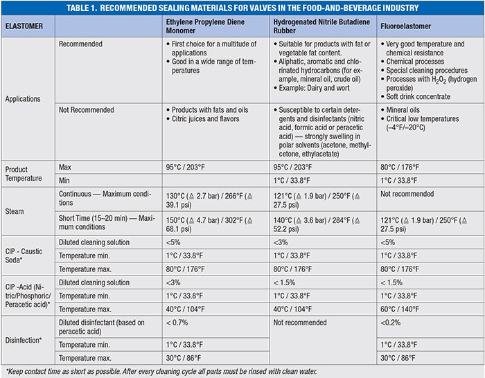
Plastics and elastomers. Different elastomers can be used for proper valve-seat sealing. The selection depends on the process parameters (such as temperature, pressure, cleaning conditions) and the characteristics of the product itself. A proper elastomer selection is important to preserve the lifetime of the elastomer as long as possible.
Major hygienic valves manufacturers follow the FDA recommendations for all sealing materials, typically the ones used are ethylene propylene diene monomer (EPDM), hydrogenated nitrile butadiene rubber (HNBR) and fluoroelastomer (FKM). Table 1 shows one of such elastomer selection guides [2].
Hygienic versus aseptic design
Hygienic and aseptic designs both focus on preventing contamination, but they differ in their approach and the level of control they achieve. Hygienic design aims to minimize the risk of contamination through the design of equipment and processes, emphasizing cleanability and ease of maintenance. Aseptic design, on the other hand, strives to create a completely sterile environment, free from all microorganisms, often involving specialized equipment and strict procedures.
Parts of a hygienic valve will move in and out of the process, becoming exposed to the surrounding environment. For instance, a rising stem on a valve will come into contact with the process and may also come into contact with the environment outside the process (Figure 1).
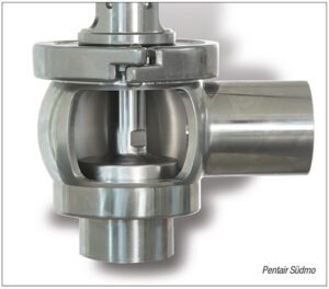
FIGURE 1. This example of a hygienic single-seat valve section shows the insert
In the case of an aseptic valve, each component of the valve that comes into contact with the process is hermetically sealed from the environment and atmosphere surrounding the process. This is achieved by adding a polytetrafluoroethylene (PTFE) diaphragm (or bellows from the past) to the stem (Figure 2).
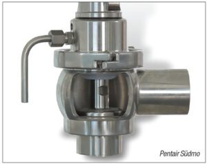
FIGURE 2. This example of an aseptic single-seat valve section shows the insert
Valve types
Several sanitary valve types exist for different applications, from shut-off operation to overpressure protection. Figure 3 shows a general decision-tree diagram to illustrate typical questions from a process design standpoint that can influence the selection of one or other type of valve; however, other factors, such as capital versus operating costs and performance trade-offs, may affect the decision. For simplicity, Figure 3 excludes the decision over whether the process will be hygienic or aseptic, as discussed earlier.
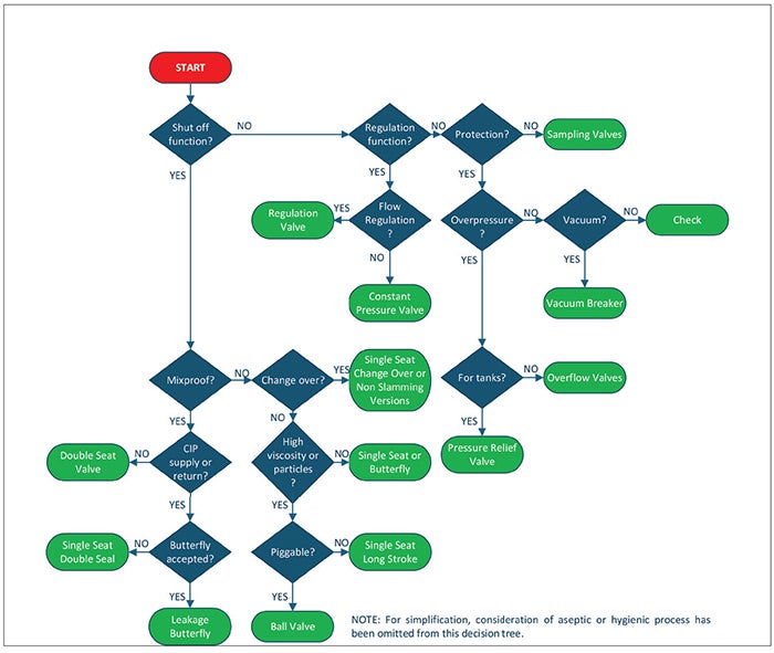
FIGURE 3. This decision-tree diagram illustrates typical questions from a process design standpoint that can influence valve selection
Butterfly valves. These valves feature a disc mounted on a rotating shaft. They are usually used as shut-off valves that are quick to operate, compact and require minimum capital expenditure (capex), in applications that require frequent cleaning and low to moderate pressure and low- to medium-viscosity liquids.
A key factor with butterfly valves is to consider sanitary fittings (weld end, flanges, threaded or clamp) to be installed properly in the pipeline, and simplified maintenance procedures. Options to operate them include standard manual handles or pneumatic actuators.
Ball valves. Ball valves comprise a spherical ball with a hole in the center to allow flow, providing reliable shut-off in on/off applications and high-pressure systems including viscous liquids or products that contain solids or semi-solids. Ball valves designed for sanitary service should be full-bore, to avoid product accumulation and facilitate cleaning, including pigging operations.
There are contradictory opinions about the use of ball valves in hygienic processes, as there are no ways to guarantee the efficacy of the CIP over the entire sphere surface.
Single-seat valves. Single-seat valves are formed by the body, the seat connected to a plug and the actuator, with compression seals located on the seat. This design entails one contact surface between the seat and the plug, providing reliable shut-off or flow diversion. The single plug moves to open or close the valve, thus being used for shut-off, changeover or diverting applications.
They are relatively simple and versatile, with modular designs that allow manual or pneumatic actuators. They are suitable for a variety of operations in food, beverage and pharmaceutical industries, being reliable and relatively easy to clean and maintain. They are available in different sizes, from fractional sizes (for example,½ or ¾ in.) to 6 in. or their equivalent in DIN sizes.
Single-seat valves can be controlled remotely using compressed air or manually operated. Nowadays, pneumatic operation is more common, with pneumatic actuators operating under normally open or normally closed conditions using air at 6 bars (87 psi).
Operating conditions for these valves include standard pressures typically up to 10 bars (145 psi) in the pipeline, with temperature ranges directly affected by the selection of sealing material, as shown in Table 1.
Single-seat valves are also available in variants tailored to specific process needs, such as the following:
- Shut-off valves to isolate sections of a pipeline
- Divert valves to redirect flow between different lines
- Tank outlet valves
- Long-stroke versions for highly viscous products or larger particles
- Tangential inlet or outlet valves
- Aseptic versions
Double-seat or mixproof valves. The main feature of mixproof valves is that they can allow two different fluids, such as products or cleaning solutions, to simultaneously flow through the same valve without risk of cross-contamination. To achieve this, mixproof valves contain two independently controlled valve seats, leaving a leakage chamber between them. The leakage chamber has a dedicated outlet, so that any potential leakage can be directed out of the system, thus avoiding mixing of the fluids and allowing detection of seal failure.
This design allows for CIP and SIP operations without removing the valve from the process line, thus reducing cleaning and maintenance downtime. Also, one mixproof valve can replace multiple single-seat valves for the same process requirement, thus simplifying piping, automation and control arrangements and typically resulting in cost savings. Various manufacturers often offer modular designs that allow flexibility for different process requirements.
FIGURE 4. Double-seat valves with seat lifting allow the upper seat to be cycled (and cleaned) while the upper pipeline is cleaned, and similarly for the lower seat
Variations of these valves include the following:
- Double-seat valves without seat lifting: In this case, the seats are cleaned by means of an external flushing chamber.
- Double-seat valves suitable for sterilization: Besides having seat lifting, these valves include a flushing chamber to flush/sterilize the shaft area.
- Double seat change-over valves: These have the same configuration as the double-seat valves with seat lifting and add a switch-over function in the lower body.
- Double-seat valves for tank outlets: These valves’ construction appears to be upside-down. In this case, one plug is cleaned with the tank and the other with the pipeline. The valve is connected to the tank via a weld-in flange.
- Double-seat valves for CIP: These valves feature a special design for CIP stations and CIP returns. Flushing of the leakage chamber occurs during cyclical lift (opening and closing).
- Double-seat valves — Pasteurized Milk Ordinance (PMO) version: As required by the PMO, these double-seat valves are based on the regular double-seat valves with seat lifting and include special features for the leakage chamber, shaft flushing and plug cycling monitor.
- Aseptic versions: These versions include flushing, diaphragm to prevent contact with the atmosphere and monitoring of all valve positions.
Single-disc, double-seal valves. In certain areas of the process plant, where there is the need to avoid the mixing of media and capex is limited, a single-disc, double-seal valve is the recommended choice.
With this type of valve, two incompatible media (for example, CIP fluid and product) can be separated in the pipelines without mixing. The valve has one plug with two separate seals, with a leakage chamber that allows to detect any potential leak (Figure 5). Additionally, the leakage chamber can be externally flushed by two valves fitted on each side.
FIGURE 5. With a single-disc, double-seal valve, two incompatible media (for example, CIP fluid and product) can be separated in the pipelines without mixing
This type of valve is typically used for the CIP supply to the process line or the CIP return. It could also be used in the construction of manifolds if the sanitization requirements are not strict.
Leakage butterfly valves. This is another cost-efficient option when two incompatible media need to be separated. These valves use two butterfly valve discs with independent vent and drain valves in a single housing to isolate the leakage chamber. Valve discs are actuated by a common mechanism that can be either a manual handle or a single pneumatic actuator.
These valves provide significant advantages over traditional block-and-bleed installations, such as reduced space requirement, reduction in installation and automation costs.
Regulation valves. Control valves are used to regulate and control process variables like temperature, flowrate or pressure, and are frequently used for dosing, blending and filling operations. Some examples of their use include concentrates inline dosing, CO2 dosing for carbonated beverages and pressure regulation in a liquid pipeline.
Proper specification of a control valve requires defining the product to be handled along with its properties (such as density, viscosity and so on), minimum, maximum and typical (most frequent or expected) values of operation of temperature, upstream and downstream pressure (along with corresponding pressure drop) and flowrate. With said information, the valve coefficients of discharge are then calculated at the different expected operation points, using Equations (1) and (2), in metric and U.S. customary units, respectively:
Metric units:
Kv = Q / √∆P (1)
where Kv is the coefficient of discharge for metric units,
Q is volumetric flowrate in m3/h,
and ∆P is the pressure drop across the valve in bars
U.S. customary units:
Cv = Q / √∆P (2)
where Cv is the coefficient of discharge for customary U.S. units,
Q is volumetric flowrate in gal/min,
and ∆P is the pressure drop across the valve in psi
Given a valve catalog, a design engineer may select a given control-valve standard model based on the range of coefficient of discharge values; nonetheless, it is highly recommended to prepare a specification sheet with the process data and the range of coefficients of discharge needed at the different expected operation points, so that the valve manufacturer can evaluate and recommend the model within their offering that best suits the service requirements. When evaluating control-valve proposals, the design engineer should compare the manufacturer-provided coefficients of discharge and reassess pressure drop calculations to ensure proper fit.
Additional considerations to be taken regarding control valve selection can include the following:
- Regulation with linear or equal percentage control plug
- Diaphragm actuator for fast and precise control or 4–20 mA, a cost-effective actuator.
- Control plug with or without shut-off function (O-ring or metal seal)
- Hygienic or aseptic valve inserts
- Valve body types for mixing or diversion
Constant pressure valves. A constant pressure valve is designed to maintain a consistent pressure level in a fluid system — regardless of fluctuations in upstream pressure or flow rates. They contribute to product quality assurance and prevent critical process disruption such as in pasteurization.
Check or non-return valves. In the CPI production environment, there are situations where unidirectional flow is essential. Typical applications include lines connecting to pump discharges or to tanks that may have higher pressures or levels than the product source. In this case non-return or check valves are used.
Pressure-relief and safety valves. Pressure-relief valves are critical safety components designed to protect tanks and process equipment from overpressure conditions. They automatically open to discharge product — typically gas or liquid — once a predefined pressure set-point is reached.
Overpressure can occur due to contingencies such as gas not properly vented during tank filling, chemical reactions that produce gas buildup inside the tank (such as fermentation) or tank overfilling with liquid.
Regarding the design, usually these valves are spring-loaded, capable of working with steam, gases and liquids. Pressure-relief valves must be calibrated at a certain set point and be delivered together with the calibration certificate.
Besides the sanitary standard design, the pressure-relief valves must adhere to international standards and directives for pressurized equipment, such as ASME (American Society of Mechanical Engineers) or PED (Pressure Equipment Directive – E.U.). These standards ensure the valves meet stringent safety, performance and reliability criteria.
Overflow valves. Overflow valves relieve pressure in closed spaces, including process lines. They can be discharged to either open or closed systems. Common applications include overpressure protection at positive-displacement-pump discharges. The output medium can be discharged or returned/directed into a closed system
For some manufacturers, this type of valve is considered an extension of their single-seat valve program as it is in fact a single seat valve with the variation in the actuator, as it features an adjustable load spring that allows setting a specific opening pressure (setpoint).
In terms of the EC Pressure Equipment Directive 2014/68/EU, overflow valves are not safety-equipped parts and do not possess any type of examination certificates [3].
Vacuum breaker valves. Tank implosion may occur due to vacuum conditions occurring as a result of emptying operations, vapor condensation, or changes in temperature between the process and the CIP fluid — for example, cleaning of milk storage silos requires that they be emptied (with the milk previously stored at 4°C (39°F)) and then subjected to cleaning conditions (with typical temperatures in the range of 80°C (176°F)).
These valves can be specified as spring-loaded (for all fitting positions) or weight-loaded (for vertical installation only).
Sample valves. Sample valves allow collection of sterile samples from the process stream.
Avoiding common pitfalls
Process design engineers are often faced with design choices that affect safety, reliability, operability, maintainability, efficiency and cost. Some common pitfalls to avoid when selecting and installing sanitary valves are discussed here.
Non-compliance with standards and regulations. Some valve types may seem suitable for a given service but may not comply with regulatory requirements in some geographies. Even if a valve type is allowed under the jurisdiction where the production plant is located, its use may be restricted in jurisdictions to which the product is intended to be exported. The design engineer needs to verify that all applicable local and international regulations and standards, and appropriate valve certifications can be secured so that the product of the plant can comply with market requirements.
Incorrect valve type selection. Ignoring specific process requirements, such as CIP media, product viscosity, presence of solids and extreme temperatures, may result in unsuitable valve type selection, leading to potential product leakage, contamination or inefficiencies. The decision tree included in Figure 3 can serve as a general selection guideline, but it is no substitute for proper communication with the manufacturing company’s engineers and complete specification of the service requirements.
Improper material selection. Inadequate selection of food-grade materials for the valve body, such as 304 or 316L stainless steel, or elastomer material for the seals, may result in product leakage, contamination, or reduced valve life. Seal material selection is particularly dependent on products handled and service temperatures, including the CIP fluid used. Table 1 contains some guidelines into the proper elastomer material selection, but standards and manufacturer recommendations should be followed.
End connection or geometry mismatch. Failure to match valve connections to the plant piping specifications (butt-weld, tri-clamp and so on) or to consider proper space for valve installation and operation may lead to installation issues and may necessitate workarounds during construction that may increase cost or affect future access to operators for valve maintenance. Incorporation of piping design engineers in the review of the valve connection specifications, and care for considering valve dimensions into the piping design is key to avoid this pitfall.
Improper installation. Failure to install valves according to manufacturer instructions may lead to incorrect flow direction, risk of water hammer or other valve malfunctions. When designing, building and commissioning the plant it is important that valve installation drawings follow the manufacturer instructions, and that valve installation is verified for compliance with said requirements.
Prioritizing cost over quality. Choosing the lowest-priced option without considering certifications and suitability for service can increase operational costs in the long term and bring risks of unplanned downtime, product contamination or regulatory non-compliance. Adequate cost-benefit analysis, selection of recognized manufacturers with certified products and well-established support can ensure long-term reliability and process efficiency. ■
Edited by Dorothy Lozowski
Acknowledgements
The authors would like to thank Mr. Danillo Pires for his insights into valve type selection.
All figures are courtesy of the authors and Pentair Südmo.
References
1. EHEDG Guidelines, doc 8 “Hygienic Design Principles” third Edition March 2018. https://www.ehedg.org/guidelines-working-groups/guidelines/guidelines/guidelines/guidelines/detail/hygienic-design-principles
2. Pentair Südmo Valve Sealing Guide, 2018.
3. Pentair Südmo Components Catalog, 2024.
Authors
 Ardis Ríos Fernández is the sales manager at Pentair Food & Beverage in Mexico (Email: ardis.rios@pentair.com; Phone:+52 55 5410 8432), driving business development for the Südmo and Haffmans QC product lines. She previously worked at SPX Flow Technology, gaining expertise in process solutions for dairy, soft drinks, and oils, and leading the systems sales team.She holds a chemical engineering degree from Simón Bolívar University (Venezuela) and a certification in business management from Tecnologico de Monterrey (Mexico). She is a speaker and Latin America board member of the International Society of Beverage Technologists (ISBT).
 Sebastiano Giardinella is an associate research scientist, project engineer at the Illinois Sustainable Technology Center (ISTC), Prairie Research Institute (PRI), University of Illinois at Urbana-Champaign (1 Hazelwood Dr. Champaign, IL 61820; Phone: +1 (217) 953-1424, Email: sg00@illinois.edu; Website: www.istc.illinois.edu) where he performs project management and technical studies in energy storage, carbon capture and utilization, and grid upgrades. He has experience in feasibility studies, corporate management, project management and process engineering consulting in projects for the chemical and energy industry in the U.S. and Latin America. He is a project management professional (PMP), holds one patent for a long-duration energy storage technology. He has cofounded an engineering design firm (www.ecotekgrp.com/en), and environmental analysis company (www.ambitek.com.pa), and a long-duration energy storage startup.