Understanding the forces acting on agitator impeller blades during turbulent flow in a mixing vessel is essential for successful and efficient operation. Presented here is information on the hydraulic force, its source, and how to calculate it
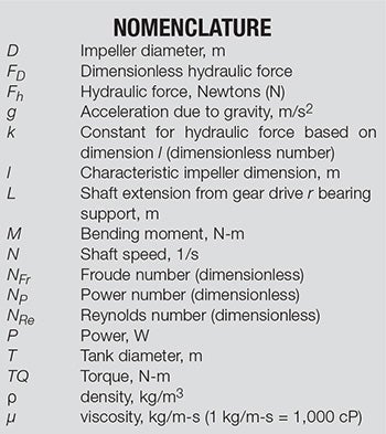 Mechanically agitated vessels are the backbone of much of the chemical process industries (CPI). The majority of such vessels are equipped with turbine agitator impellers, with a D/T (impeller diameter to tank diameter) ratio between 0.2 and 0.8. Typical examples are found in Figure 1. Such impellers are primarily used for low- to medium-viscosity (1–50,000 cP) fluids, although, if heat transfer is not a major concern, these impellers can and have been used successfully for fluids with higher viscosities (>500,000 cP) [1]. Since mechanical design and reliability are paramount for successful operation in an agitated tank, it is important to understand the loads created by agitator impellers. This article focuses mainly on the loads created by turbine impellers operating in turbulent flow, though laminar flow is also discussed briefly at the end.
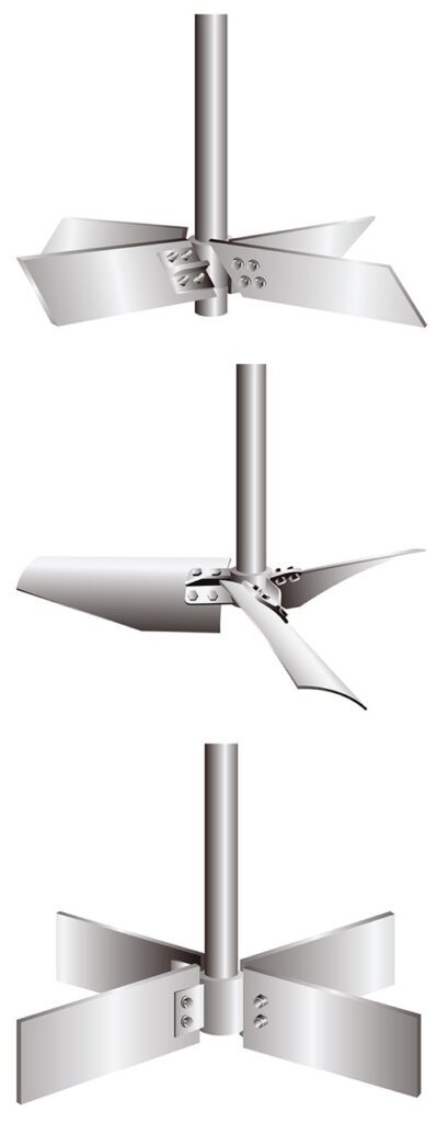
FIGURE 1. Typical turbine-blade agitators for mixing vessels can have different blade geometries, as shown in the images here
Forces on agitators
An agitator assembly must withstand a variety of loads. Figure 2 illustrates these loads, excluding thrust loads, which are not within the scope of this article. The main loads affecting shaft design are the torque (TQ) and the bending moment (M). The torque is calculated using Equation (1).
TQ = P/2πN (1)
where P is the design power draw.
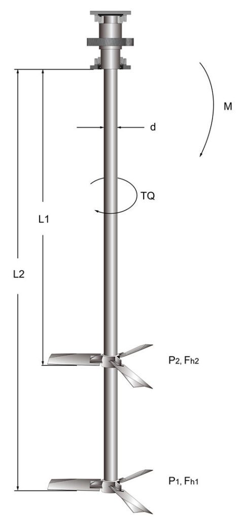
FIGURE 2. The torque and the bending moments are the main forces affecting shaft design
Bending moment for a cantilevered (supported at one end) shaft is calculated using Equation (2).
M = ∑(Fh × L) (2)
where Fh is the lateral unbalanced hydraulic force produced by an impeller (peak value), and L is the distance of each impeller from the gear drive or other support bearing. This lateral force requires some understanding of its cause and how to predict its magnitude.
Unbalanced hydraulic force
During many of the agitation training seminars conducted by the author over the years, a common reaction to the first mention of an unbalanced hydraulic force is surprise. Some have asked, “Why don’t you just balance the impeller or make sure it is fully symmetrical?” The answer is that the unbalanced hydraulic force is not due to a mechanical imbalance or lack of symmetry. Instead, it is due to the nature of turbulence. Imagine riding along in a car at highway speeds, with your arm hanging out the window. If you have done this, you probably noticed that the wind force on your hand is not constant. Indeed, your hand would be buffeted about. It is the nature of turbulence that flows and forces may have a mean value, but there is a random component that varies in both time and direction. In the case of an agitator impeller, the force on each blade has a fluctuating component. That component is not synchronized among the several blades, thereby resulting in a net fluctuating sideload called the hydraulic force. Since the magnitude of the force is not constant, designers have tried to find out empirically what the peak magnitude of such forces is, and design accordingly.
Of course, if an impeller is mechanically imbalanced or if it is asymmetrical, or mounted asymmetrically, this will increase the design loads. In this article, the focus is on the hydraulic forces, rather than mechanical imbalance. The article briefly touches on asymmetric mounting and other factors, which increase hydraulic loads.
Calculating hydraulic force
In Ref. 2, a theoretical basis for hydraulic force is presented, as well as various methodologies for measuring it [2]. Ref. 2 presents data plots showing the variation of such forces with time. It is important to understand that these forces arise mainly due to turbulence, and thus are dependent on the impeller Reynolds number (ρD2N/μ). For fully turbulent flow, the impeller Reynolds number will be 10,000 or higher. The calculations presented here will be based on turbulent flow.
Reference 2 states that the fluctuating hydraulic force on the impeller is proportional to the torque, divided by some characteristic length dimension of the blades. Equation (3) states this mathematically.
Fh = k × (TQ/l) (3)
where k is a constant and l is the characteristic length.
The value of k depends on impeller type, the number of blades, the position in the tank and any asymmetry in the tank or mounting configuration. The value of l likely depends mostly on impeller type, but is difficult to determine. Ref. 3 proposes a simpler method: just use the impeller diameter as the reference dimension, as shown in Equation (4).
Fh = FD × (TQ/D) (4)
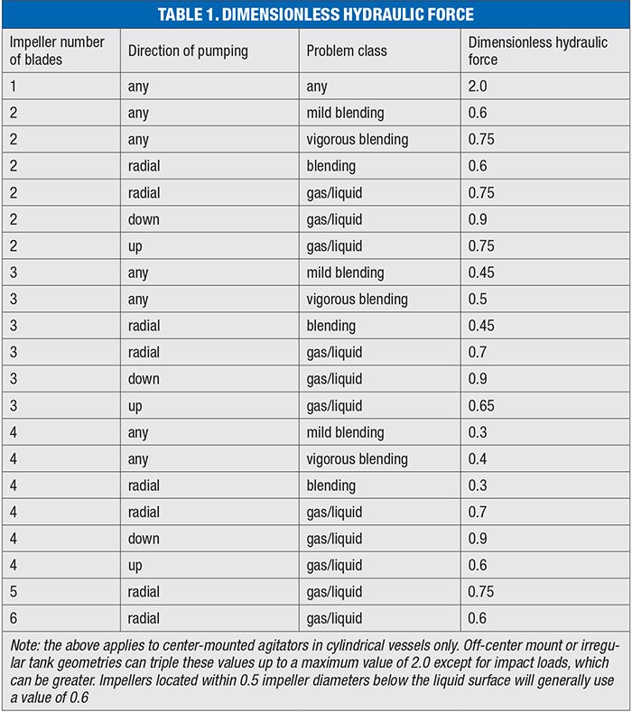
where FD is called the dimensionless hydraulic force.
Therefore, it is easy to calculate a design hydraulic force if the impeller power-draw characteristics are known and FD is known.
Table 1 lists estimated values of FD for a variety of classes of impellers under a variety of operating conditions. All are based on turbulent flow, and all are based on center-mounting in a vertical cylindrical tank. A typical example would be a three-bladed impeller pumping down in a mild blending application. This would equate to a scale of agitation of 5 or less, according to the descriptions in Ref. 4. The value of FD from Table 1 is therefore 0.45.
Calculation example
Suppose there is a 1.5-m diameter, three-bladed hydrofoil impeller rotating at a shaft speed of 45 rpm (0.75 revolutions per second) in a fluid with a density of 1,200 kg/m3 or a specific gravity of 1.2. Assume a typical power number for a hydrofoil of 0.3, and the liquid volume is such that the resultant level of agitation is mild to moderate. Power draw may be calculated using Equation (5):
P = NP × ρ × N3 × D5 (5)
= 0.3 × 1200 × (0.45) 3 × (1.5) 5 = 249 W
Torque may be calculated using Equation (1):
TQ = P/(2πN) = 249/(2 × π × 0.45) = 88 N-m
Hydraulic force may then be calculated using Equation (4):
Fh = FD × TQ/D
= 0.45 × 88/1.5 = 26 N = ~6 lb. of force
This value may seem like a small number, but it will often be applied to a large moment arm, which could result in a substantial bending moment. For example, if the shaft extension to the impeller location were 5 m, the resulting bending moment would be 130 N-m, which is greater than the torque. This situation is common.
Impellers at liquid level
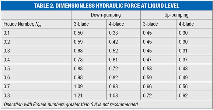
Operating a turbine impeller at the liquid surface can create much higher forces than those observed when the impeller is completely submerged. If this occurs continuously, or for an extended period of time, impellers must be designed to handle the loads. In Ref. 5, the authors suggest a dimensionless hydraulic force value of 0.75 to 1.05 for three-blade axial impellers, and 0.6 to 0.9 for four-blade pitched-blade turbines. Aside from the somewhat wide range of these values, the stated figures fail to account for the strong dependence on Froude number or direction of pumping.
The Froude number represents the ratio of inertial to gravitational forces, and is expressed in Equation (6):
NFr = N2D/g (6)
where g is the local gravitational acceleration constant.
Full-scale data on large equipment (witnessed by the author) have demonstrated that the hydraulic force operating at liquid level is much higher when the agitator is down-pumping compared to up-pumping. Table 2 lists the dimensionless hydraulic force values the author recommends as a function of Froude number, pumping direction and number of blades for axial or pitched-blade turbines. Values for radial-flow impellers are unknown to the author, but are expected to be between the up- and down-pumping direction values. Designers should use whichever value is greater between Tables 1 and 2.
Irregular mounting conditions
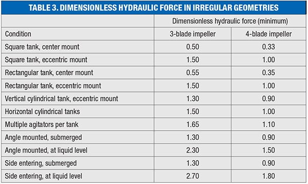
So far, all we have discussed has been for center-mounted agitators centered in cylindrical tanks. But there are cases where the mounting is less symmetrical. This can include off-center mounting, angle mounting, square or rectangular tanks, horizontal cylindrical tanks, multiple agitators per tank and possibly many others situations. Table 3 is the author’s guide to the minimum hydraulic factor that should be used. If other conditions are present, use the greatest value from Tables 1, 2 and 3.
Starting in settled solids
Starting an agitator impeller in settled solids can produce severe loads, depending on a number of factors, such as the properties of the bed of solids, whether or not the impeller is actually buried in the solids, and so on. This matter really demands its own treatment, so the reader is referred to Ref. 6.
Laminar flow and impeller types
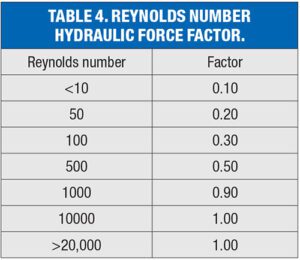
At its outset, this article stated that the main cause of the lateral hydraulic force is turbulence. It therefore follows that, if there is no turbulence, there is no random hydraulic force, so the value of FD in a center-mounted vertical application should theoretically be zero in laminar flow. Of course, there will still be some sideloads due to shaft runout, impeller imbalance and lack of perfect symmetry, but these loads are normally quite small. If the agitator is mounted off center, there will be loads due to asymmetric flow patterns, but these will also be reduced in laminar-flow situations. Though the author is unaware of any studies done for irregular mounting in laminar-flow applications, it is suggested that the values in Table 3 be multiplied by 0.5 for Reynolds numbers below 100. For situations described in Tables 1 and 2 (except for one-bladed impellers), it is suggested that the values in Tables 1 and 2 be multiplied by the factors in Table 4, as a function of Reynolds number. Reynolds number is defined in Equation (7).
NRe = D2Nρ/μ (7)
Many laminar-flow applications use close-clearance impellers, such as helical ribbons, anchors, gate impellers and others. Because they are axisymmetric, they should have little or no random hydraulic force. Moreover, they would contact the vessel wall before any serious shaft bending could occur, as they are typically applied at D/T ratios of 0.9 to 0.98. We will therefore not be discussing hydraulic force calculations for these kinds of impellers here.
Going forward
Though it is important to understand impeller hydraulic forces to properly design agitation equipment for mechanical reliability, there has been little published in the literature about this topic. It is my hope that this article will provide a somewhat conservative set of guidelines for design, and that more quantitative studies will be published in the future.
Edited by Scott Jenkins
References
1. Benz, G., Consider Hydrofoil Impellers for Laminar-Flow Mixing, Chemical Engineering Progress, May 2018, pp. 30–35.
2. Weetman, R. and Gigas, B., Mixer Mechanical Design-Fluid Forces, Proceedings of the 19th International Pump Users Symposium, February 2002, pp. 203–213.
3. Benz, G., “Agitator Design Technology for Biofuels and Renewable Chemicals,” Chapter 15, Wiley Interscience, 2022.
4. Hicks, R., Morton, J. and Fenic, J., How to design agitators for desired process response, Chem. Eng., April 1976, pp. 22–30.
5. Paul, E. and others, “Handbook of Industrial Mixing,” Chapter 21, Wiley Interscience, 2004.
6. Benz, G., How to Re-Suspend Settled Solids in an Agitated Tank, Chemical Engineering Progress, January 2023, pp. 36–42.
Author
 Gregory T. Benz is president of Benz Technology International, Inc. (2305 South Clarksville Road, Clarksville, OH 45113; Phone: 937-289-4504; Email: g.benz@benz-tech.com.com). He received a B.S.Ch.E. from the University of Cincinnati in 1976, and has taken a course on fermentation biotechnology from The Center for Professional Advancement. A registered professional engineer in Ohio, he has over 48 years experience in the design of agitation systems, specializing in polymer reactors, fermentation and bioreactors. Currently, his company does agitation, mixing and bioreactor design consultation, including designing pilot protocol, scaling up, equipment specification and bid evaluation. He has designed more than 150 fermenter agitators, as well as many polymer and biofuel agitation systems. He is a member of AIChE, ISPE, SIMB, SBE, American Mensa and the American Chamber of Commerce in Shanghai. He is an affiliated expert with Lee Enterprise Consulting Partners. He has authored more than 45 technical articles and two books.