Bulk solids are frequently used as reactants, catalysts or products in chemical process industries (CPI) operations. Often, they must be heated or cooled so that they can be handled safely or processed at a desired temperature. Traditionally, heat transfer to or from powders is carried out using heated or water-cooled screws, fluidized beds or rotating drums. However, a more economical means of heating or cooling bulk solids may be to use a direct-contact, bulk-solids heat exchanger.
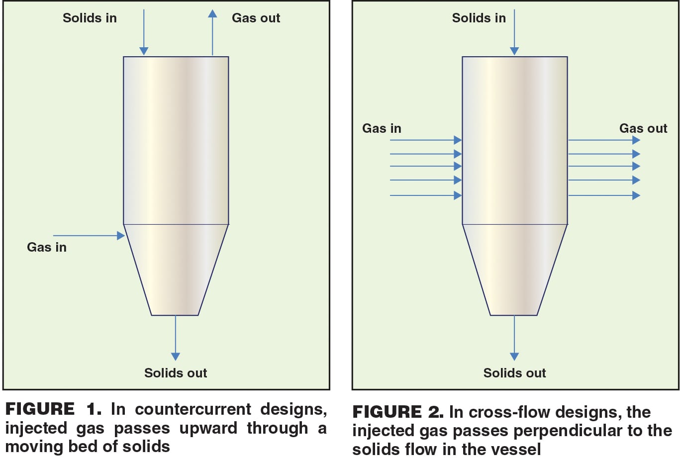
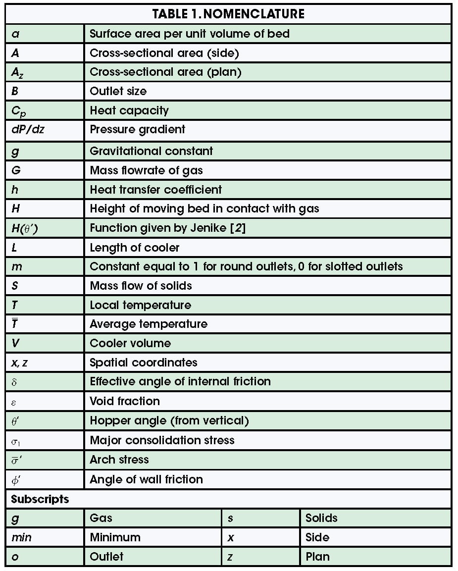
These devices are designed as hoppers, bins or silos that have been modified to allow for the injection of air or another gas. Heat transfer takes place between the powder and gas when the two streams are fed at different temperatures. The cooling or heating gas can be injected from the bottom of the bulk-solids heat exchanger, such that it passes upward through the moving bed of solids (countercurrent), or it can be injected through the walls of the vessel so that it flows perpendicular to the solids flow (cross-current). Countercurrent and cross-flow designs are shown in Figures 1 and 2.
Direct bulk-solids heat exchangers offer a number of advantages over other types of heating or cooling equipment. Because there are no moving parts, capital costs and maintenance expenses are low. They are ideally suited for heat-sensitive materials because using this approach, the temperature of the solids changes gradually. Direct heat exchangers can also be used to remove trace volatile compounds, or when a humid gas is injected, to provide the residence time necessary to condition a powder.
This article discusses the design criteria for a bulk solids cooler — a direct-contact heat exchanger that is used to reduce the temperature of a bulk material. The same procedure can be used to design a solids heater except that, of course, a hot gas is used to raise the temperature of the bulk material.
In order for a direct-contact heat exchanger to operate effectively, the following are required:
Adequate heat transfer. Sufficient thermal mass (that is, the product of the gas flowrate and its heat capacity) must be provided to allow the solids to be cooled to the desired temperature.
Uniform solids flow.The solids-velocity profile must be uniform, otherwise, the exposure of the solids to the cooling gas will be inconsistent, and heat transfer will be insufficient. In extreme cases, solids will only flow in a central channel above the cooler outlet, resulting in significantly less residence time and insufficient heat transfer.
Proper outlet size. The outlet of the cooler must be large enough to prevent obstructions to flow from developing and allow discharge of the tempered product at the desired rate.
Reliable gas flow. For countercurrent designs, the distributor that injects the gas must provide a constant gas velocity throughout the cross-section of the vessel. The gas velocity must be low enough to prevent fluidization, otherwise, channeling will cause the gas to bypass a portion of the solids and create other flow instabilities.
With cross-flow designs, the gas velocity must be low enough to prevent pinning, which occurs when the friction between the solids and the permeable wall through which the gas exits becomes too great and prevents solids flow along the wall. Excessive gas velocity may also push the solids away from the permeable wall through which the air enters the cooler. As a result, the air will begin to escape upward along the wall rather than through the bed.
Sufficient cooler volume.The required heat duty depends on the heat-transfer coefficient between the gas and solids, the total surface area and the temperature driving force. The available heat-transfer area in a direct-contact bulk solids heat exchanger is the product of the powder’s specific surface area (that is, its surface area per unit volume) and the volume of the bed of material in the cooler.
Heat transfer
The temperatures of the gas and solids streams entering or leaving the cooler are generally known. In most cases, the temperatures of the solids entering and leaving the cooler are specified, as is the temperature of the cooling gas. A steady-state energy balance of the gas and solids can be written as according to Equation (1):
![]() (1)
(1)
(Table 1 provides the nomenclature for all terms used here.) The energy balance, as written, assumes that only sensible heat is transferred — thus, that there is no condensation or evaporation. Otherwise, a term that describes the latent heat would have to be included in the energy balance. In addition, Equation (1) assumes that heat losses from the cooler are negligible.
The minimum gas injection required to obtain the target temperature of the solids product, Gmin, can be determined by performing the energy balance over an infinitely tall cooler, using Equation (2):
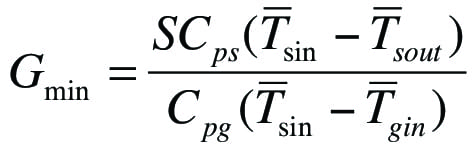 (2)
(2)
The design gas feedrate must exceed the Gmin. Alternatively, an approach temperature (the difference between the inlet gas and outlet solids temperatures) can be specified.
Solids flow
Two primary flow patterns can occur in a bin or silo: mass flow and funnel flow (Figure 3).
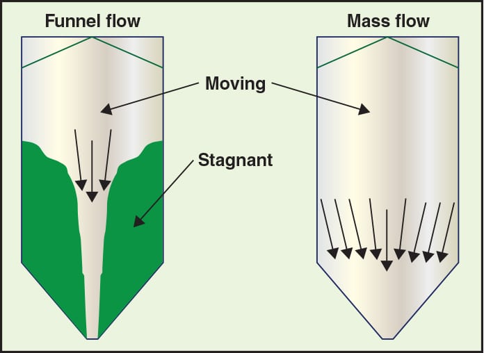
FIGURE 3. Two types of flow typically arise in bulk-solids vessels. In general, mass flow (right) is preferred over funnel flow (left)
Funnel flow.When funnel flow occurs, an active flow channel forms above the outlet, with stagnant material (this solids buildup is called a rathole) remaining at the periphery. Funnel flow can cause erratic flow, reduces the solids residence time, and induces high loads (depending on vessel size) on the structure and downstream equipment due to collapsing ratholes and eccentric flow channels. In the case of countercurrent designs, gas is likely to flow preferentially in the central flow channel because of its lower permeability. Funnel flow occurs when the walls of the hopper section of the cooler are not steep enough or low enough in friction for the solids to flow along them.
Mass flow. Mass flow is the preferred pattern in a bulk-solids heat exchanger. In mass flow, the entire bed of solids is in motion when material is discharged from the outlet. This flow behavior eliminates stagnant regions in the vessel and results in a first-in, first-out flow sequence, which provides a more uniform velocity profile. A uniform gas-velocity profile also allows uniform tempering of the solids when the gas flow is countercurrent. Mass flow occurs when the walls of the converging section of the cooler are steep enough and have low enough friction, thereby enabling the bulk material to flow along them.
The recommended hopper angle to ensure mass flow is readily calculated from wall friction results. The angle of wall friction ø´ is obtained by following the method described in ASTM D-6128 [ 1]. The test is performed using an instrument in which a sample of powder is placed inside a retaining ring on a flat coupon of wall material. Various normal loads are then applied to the powder. The ring and powder in the ring are forced to slide along the stationary wall material, and the resulting shear stress is measured as a function of the applied normal stress.
After a number of values have been recorded, the wall yield locus is constructed by plotting shear stress against normal stress. The angle of wall friction ø´ is the angle that is formed when a line is drawn from the origin to a point on the wall yield locus. A representative wall yield locus is shown in Figure 4.
Design charts originally developed by Jenike [ 2] provide allowable hopper angles for mass flow, given values of the wall friction angle and î¤, the effective angle of internal friction (which is determined by shear-cell testing; this is discussed later). These charts are summarized in Figures 5 and 6 for conical and planar hoppers (for example, wedge-shaped hoppers and transition hoppers), respectively. The outlet of a wedge-shaped hopper must be at least three times as long as it is wide for Figure 6 to apply. Values of the allowable hopper angle îµ´ (measured from vertical) are on the ordinate, and values of the wall friction angle ø´ are on the abscissa. Any combination of ø´ and îµ´ that falls within the mass-flow region of the chart will provide mass flow.
Hoppers with round outlets should not be designed at the theoretical mass-flow hopper-angle value. Otherwise, a small change in powder properties may cause the flow pattern inside the hopper to change from mass flow to funnel flow, with its associated risk of flow problems. Therefore, a 3-deg margin of safety with respect to the mass- flow hopper angle given in Figure 5 is recommended.
Sloping walls required for mass flow in wedge-shaped hoppers can be 10 to 12 deg less steep than those required to ensure mass flow in conical hoppers. Wedge-shaped hoppers are frequently used for materials that have high wall friction.
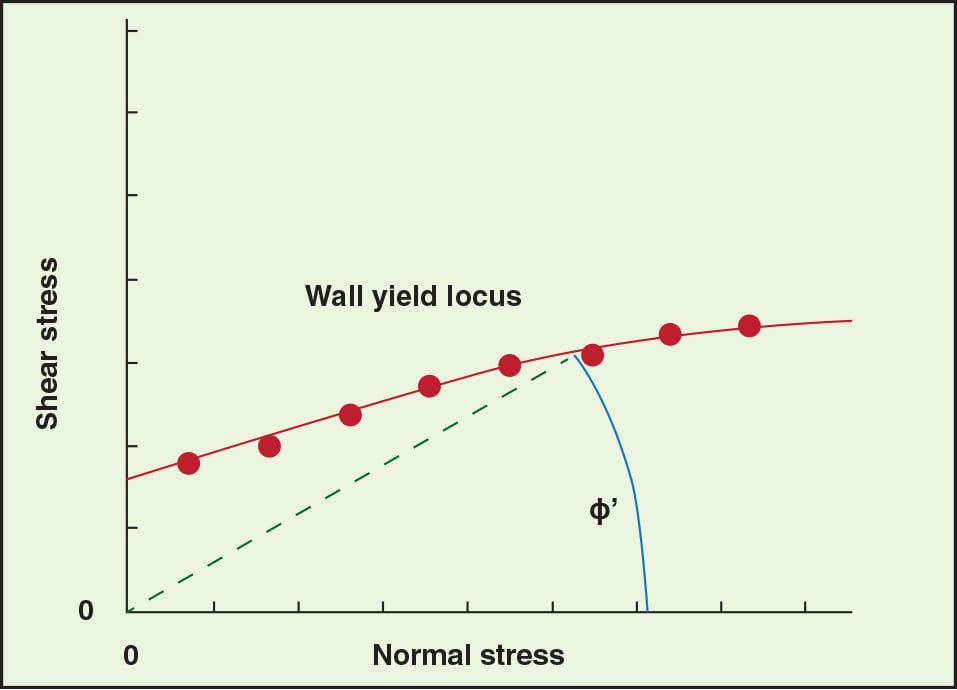
FIGURE 4. The angle of wall friction, ɸ’, is determined by the wall yield locus, which is constructed by plotting shear stress against normal stress
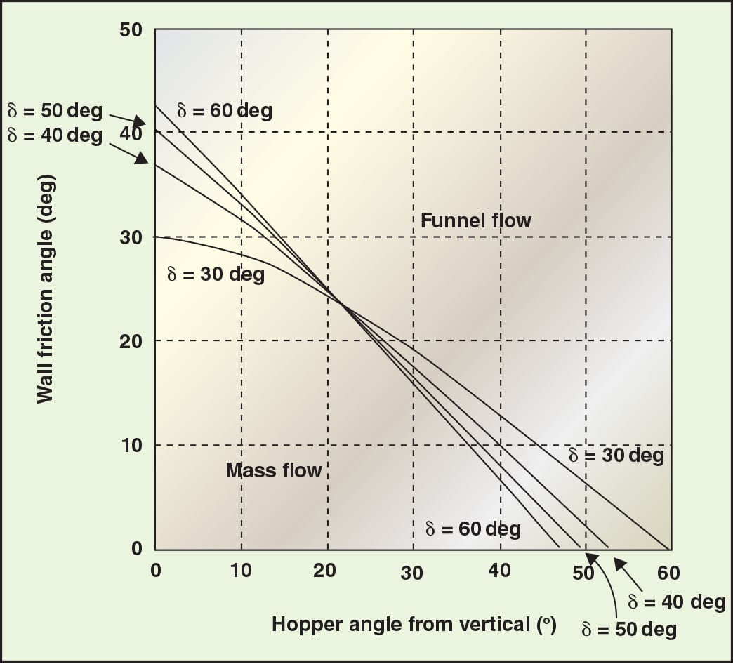
FIGURE 5. This plot shows the theoretical mass-flow hopper angles for hoppers with round or square outlets. Note: A minimum safety factor of 3 deg should be used
Outlet size
The outlet of the cooler must be large enough to prevent an arch from forming, which would prevent flow completely. In addition, it must be large enough to allow the required discharge rate. The required outlet size is a function of the bulk density, the wall friction, the internal friction, the cohesive strength, and the permeability of the bulk solid.
Cohesive arching will take place if the cohesive strength of the bulk material, which develops as a result of its consolidation in the cooler, is greater than the stresses imparted onto it at the cooler outlet.
The cohesive strength of a powder is measured by shear-cell testing following methods described in ASTM standards [ 1, 3]. A sample of powder is placed in a split cell and pre-sheared under a normal load until the flow of the moving layer of powder is steady. The sample is then placed under a reduced load and sheared until failure. The pre-shear and shear steps are repeated for a number of normal loads and the yield locus is determined from a plot of the failure shear stress against the normal stress, from which the bulk material’s cohesive strength can be established. The test is repeated over a range of consolidation pressures to determine the relationship between the major consolidation stress and the cohesive strength of the powder. This relationship is known as the material’s flow function. A shear cell test also provides the material’s angle of internal friction.
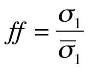
Once a material’s flow function has been determined, the minimum outlet width or diameter that will prevent cohesive arching can be calculated using the hopper’s flow factor, ff. Jenike defined the flow factor using the relationship shown in Equation (3):
 (3)
(3)
where:
î³´ is the stress acting on the abutments of the arch
The flow factor is a function of the powder’s effective angle of internal friction, the hopper angle, and the wall friction angle. Charts that provide flow factors for conical and wedge-shaped hoppers can be found in Jenike [ 2].
Superimposing the material’s flow function and flow factor on the same graph allows the cohesive strength and arch stress to be compared. There are three possibilities:
• The flow function lies below the flow factor and the two curves do not intersect. When this is the case, the stress imparted on the arch is always greater than the material’s cohesive strength, and there is no minimum outlet-dimension requirement to prevent cohesive arching
• The flow function lies above the flow factor and the curves do not intersect. The bulk solid will not flow due to gravity alone, so another means of discharging the powder must be employed
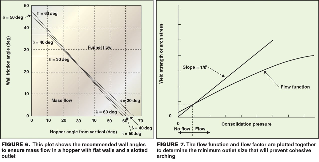
• The flow function and flow factor intersect, as shown in Figure 7. At the point where the two lines intersect, the arch stress and the cohesive strength of the bulk solid are the same and equal to the critical stress, î³cr. The minimum outlet diameter or width to prevent a cohesive arch from developing, Bmin, can then be calculated using Equation (4):
 (4)
(4)
The function H (îµ´) is given by Jenike [ 2] and is approximately 2 for conical hoppers, and 1 for wedge-shaped hoppers. The function H(îµ´) is shown in Figure 8.
FIGURE 8. The function H (îµ’) is used ito calculate the outlet dimensions that will prevent arching in mass flow hoppers
The outlet of the cooler must also be large enough to allow the required discharge rate. For coarse powders, the maximum discharge rate can be calculated from Equation (5):
 (5)
(5)
The parameter m is equal to 0 for slotted outlets, and equal to 1 for round or square outlets. The mass discharge rate is equal to the product of the velocity, outlet cross-sectional area, and the material’s bulk density at the outlet.
The maximum flowrate of a fine powder can be several orders of magnitude lower than that of coarser materials due to an adverse gas pressure gradient that forms. Because of vacuum that naturally develops above a hopper outlet when the voids in fine powders expand during discharge, the resulting counterflow of gas will hinder solids flow. A limiting condition occurs when compaction in the cylinder section forces too much gas out through the material top surface.
If the permeability and the compressibility (that is, the bulk density-pressure relationship) of the powder are known, the pressure gradient can be calculated by an analysis given by Ref. 4. The permeability of a powder is determined by passing air through a bed of volume and measuring the resultant pressure drop.
Gas distribution
 |
| FIGURE 9. Improved gas uniformity can be achieved by injecting gas via crossbeams and an annulus, such as those shown here |
With direct bulk-solids coolers that operate in counterflow mode, the gas must be distributed evenly throughout the moving bed of solids. Mass flow is essential, otherwise, stagnant material — with a much lower permeability — will have dramatically less contact with the cooling gas. The gas distribution system must be designed such that there are no regions with high gas velocities. Localized fluidization will cause channeling, bypassing of the solids and flow instabilities. Therefore, designs that involve nozzles or perforated plates should be avoided.
Gas uniformity can be improved by injecting the gas into the bed of solids via an annulus and a set of crossbeams located at the intersection of the cylindrical and hopper sections of the cooler. Gas can also be introduced underneath an inverted cone, whereby the air enters the bulk material directly through the free surface that forms. Properly designed gas distribution systems are shown in Figure 9.
The gas velocity in a countercurrent direct cooler must be low enough to prevent fluidization of the bulk solid. Once the required gas-injection rate has been determined based on an energy balance, the cross-sectional area of the cooler that ensures that the superficial gas velocity is well below the powder’s permeability throughout the cooler can be specified.
In a cross-current heat exchanger, the cooling gas flows horizontally across the bed of solids through permeable walls. Cross-flow designs are often advantageous because lower pressure drops and greater gas fluxes can be achieved.
For cross-flow designs, the gas velocity must be low enough to prevent pinning or cavity formation. Pinning occurs when the frictional force between the powder and the wall through which the gas exits is high enough to prevent flow along the wall. A cavity can form if the stress caused by the movement of air through the powder along the wall through which the gas enters causes a gap to form between the powder and wall. As a consequence, gas may flow vertically rather than transversely through the bed.
Cooler volume
The rate of heat transfer depends on the temperature driving force in the cooler, the heat-transfer coefficient between the gas and solids, and the surface area per unit volume of the bulk material.
The following can be used to calculate the volume of bulk material that must be in contact with the cooling gas in a countercurrent direct-contact heat exchanger.
 (6)
(6)
The design of cross-flow bulk- solids coolers is somewhat more complicated since the temperature of the solids leaving the heat exchanger will vary with location.
An analytical solution exists [ 5] for the system of equations that can be used to calculate the temperature profile of the solids leaving the cooler, as shown in Equation (7):
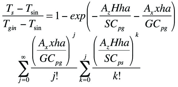 (7)
(7)
Equations (6) and (7) are valid provided that heat losses to the surroundings and radiation heat transfer can be neglected and heat transfer by convection dominates.
Closing thoughts
Hoppers, bins and silos that are used to handle bulk solids can also be used as heat exchangers that heat or cool the materials. The moving-bed processor must allow uniform flow of solids and gas, and the dimensions of the vessel must ensure that instabilities do not result from high gas velocities. The gas must be injected at a rate high enough to ensure a temperature difference between the solids and gas phases throughout the column and the volume must be great enough to provide the required residence time. Obtaining fundamental, bulk-solid flow properties, including cohesive strength, wall friction, compressibility and permeability, along with thermal properties and heat-transfer rate information, is necessary to ensure that the moving-bed heat exchanger will operate as desired.
Edited by Suzanne Shelley
References
1. ASTM D-6128, Standard Test Method for Shear Testing of Bulk Solids Using the Jenike Shear Cell, ASTM International, 2006.
2. Jenike, A.W., Storage and Flow of Solids, Bulletin 123, University of Utah Engineering Station, 1964, Revised 1976.
3. ASTM D-6773, Standard Shear Test Method for Bulk Solids Using the Schulze Ring Shear Tester, ASTM International, 2008.
4. Royal, T.A. and Carson, J.W., Fine Powder Flow Phenomena in Bins, Hoppers, and Processing Vessels, presented at Bulk 2000: Bulk Material Handling Toward the Year 2000, London, 1991.
5. Almendros-Ibáñez, Soria-Verdugo, A., Ruiz-Rivas, U., and Santana, D., Solid conduction effects and design criteria in moving bed heat exchangers, App. Therm. Engr., 31, 1200, 2011.
Author
 Greg Mehos is a senior project engineer with Jenike & Johanson, Inc. (400 Business Park Dr., Tyngsboro, Mass.; Phone: 978-649-3300; Email: gmehos@jenike.com), and an adjunct professor at the University of Rhode Island. Mehos has been involved in a wide range of bulk solids handling projects, including designs of hoppers, dryers, gasifiers and moving-bed reactors, as well as analyses of purge and conditioning columns. He received his B.S. and Ph.D. in chemical engineering from the University of Colorado and an M.S.Ch.E. from the University of Delaware. He is a registered Professional Engineer in Colorado and Massachusetts and a member of AIChE. He served on the executive board of AIChE’s Particle Technology Forum and is a past chair of the Boston AIChE section.