To meet bold sustainability targets, new burner technologies and control configurations are being developed to help significantly reduce NOx emissions
Many industry-leading businesses have set bold sustainability goals for emissions reduction and energy efficiency driven by factors such as climate change, the Paris Agreement and various national, state and local regulations.
In the U.S., California has always led the way in emissions reduction. It was the first state to mandate an emissions standard of 30 parts per million (ppm) for oxides of nitrogen (NOx), which subsequently decreased to 15 ppm NOx and to then just 9 ppm NOx. Now, some counties in California are enforcing a 2 ppm NOx requirement on larger industrial watertube (IWT) boilers. Other states will be following suit with 30 ppm or even lower NOx emissions requirements.
The boiler industry continues to introduce advanced technologies and solutions that reduce both NOx and CO emissions (Figure 1). Today, there are various combustion technologies and firing styles, depending on application, fuel and firing size, that are available for traditional and renewable fuels. These newer offerings coupled with advanced control systems ensure high turndown, a consistent fuel-to-air ratio and repeatability in combustion.
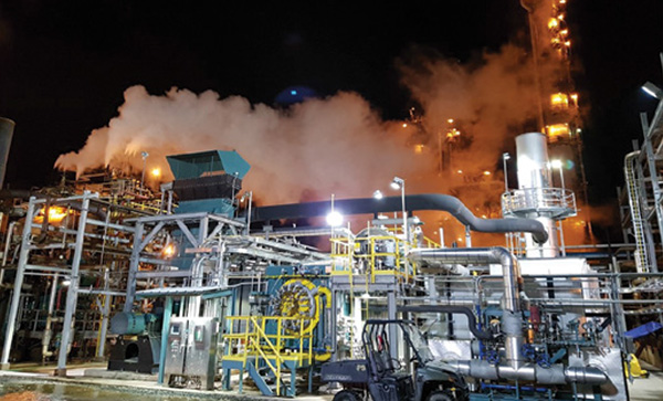
FIGURE 1. Lower NOx and CO emissions requirements are forthcoming, and burner technologies are evolving to help achieve these goals
Turndown is a concept that is important to understand. Regarding boiler systems, it is a ratio that identifies a system’s high-fire and low-fire settings. For example, a 100-million Btu/h burner with 10:1 turndown will reach high fire at 100 million Btu/h and low fire at 10 million Btu/h. The main benefit of high turndown for a boiler system is reduced cycling, which reduces the energy consumption and thermal stress of a boiler.
By reducing cycling, less fuel is needed and fewer emissions escape into the atmosphere. Turndown is highly dependent on the burner design. Many high-turndown burner systems require an advanced control system — typically, these either involve parallel positioning or fully metered systems.
NOx types
- It is first critical to understand that there are three different types of NOx.
- Thermal NOx is based on temperature and makes up most of the NOx formed during combustion
- Prompt NOx is formed when molecular nitrogen in the air combines with the fuel in fuel-rich conditions
- Fuel-bound NOx is based off nitrogen in the fuel and is a natural occurrence during combustion
The type of NOx that is reduced most with burner technology is thermal NOx. This can be achieved by lowering the temperature of the flame or by eliminating prompt NOx, some of which can be reduced by optimizing the fuel-to-air mixture in the burner. There are different types of burner technologies and combustion systems that can be implemented today, and each one has its own characteristics to reduce NOx and increase efficiency. These methods include the following:
- Fuel staging
- Fuel staging with fluegas inducers
- Fuel- and burner-induced fluegas recirculation (FGR)
- High excess air
- Two-step combustion (fuel and air injection)
- Selective catalytic reduction (SCR) can be added on these technologies to reduce a plant’s emissions and NOx
Fuel staging
Fuel staging injects a portion of the main fuel to mix with combustion gases in the furnace prior to ignition (Figure 2). Thus, it dilutes the fuel with gases, primarily N2 and H2O. Staging the fuel in this manner causes it to ignite off the main flame, and the volume decreases the amount of radiant-heat transfer of the furnace. This radiant-heat transfer helps to cool the flame. Combustion of these two effects reduces the flame temperature, thus lowering the NOx formation.
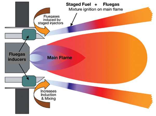
FIGURE 2. Fuel staging with fluegas inducers involves injecting a portion of the main fuel into the furnace prior to ignition, which serves to dilute the fuel with gases, effectively lowering the flame temperature and inhibiting NOx production
Behind the process, some of the gas injectors on the outer side of the combustion head (or perforated portion of the head) have a single, large grill in them, called staged injectors. These injectors direct the fuel jets on the outside of the main flame combustion.
Larger injection orifices produce larger jets that travel further into the furnace itself. Mixing more slowly before igniting on the main flame produces a larger flame envelope that helps to increase the radiant heat transfer. More heat transfer from the boiler to the furnace and into the flame itself yields more heat and increases NOx emissions.
Fuel staging by itself can reduce NOx by about 20–25%. For example, for a 100-ppm NOx standard uncontrolled type of burner with fuel staging in place, NOx emissions can be reduced to 75–80 ppm.
Induced fluegas recirculation
Induced fluegas recirculation (FGR) is one of the most common and efficient methods to reduce thermal NOx (Figure 3). The process takes cool, inert fluegas and mixes it with combustion air to increase mass flow through the flame front, thus reducing the temperature and thermal NOx formation.
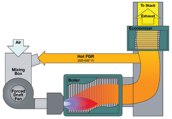
FIGURE 3. A typical firetube boiler with fluegas recirculation (FGR) is shown, where the hot recirculated gas stream is diverted before reaching the economizer
Figure 3 demonstrates how the fluegas is pulled out before it reaches the economizer. On a small firetube with higher temperatures, recirculated fluegas will be pulled off and mixed with the air. From there, with the fan, it will be introduced and mixed with the fuel into the combustion process. This will minimize the flame temperature to reduce thermal NOx and lower burner emissions.
This technique is used in many combustion engines today. It can be called exhaust gas recirculation (EGR). Basically, it is a simple solution. By adding a little water, the system cools down. It can be likened to putting fluegas in the system to help cool down the flame and keep NOx emissions low.
For larger-capacity boilers, such as IWTs, FGR will typically be taken off after the economizer. On larger boilers, it is preferred to have slightly cooler temperatures for FGR.
NOx can be reduced by 90% when utilized with other burner technologies. With internal technology, 9–10 ppm NOx is achievable when combining multiple technologies. Today, even 5 ppm NOx is achievable in certain circumstances.
High excess air
The high excess air method increases the mass flowrate of excess air to cool the flame, similar to the FGR solution. To be effective, it is necessary to control the flame-front position. Also, it is very important in this method for the fuel-and-air mixture to be premixed prior to burner ignition. Otherwise, the flame will move up and flow into a fuel-rich condition. Once that happens, the burner will go into displacement, and the flame temperature will start to rise again, counteracting the benefits of premixing.
Because the fuel and air mixture must be premixed and control of the flame position is required, a high excess air strategy can only be used with certain types of burners.
Utilizing this type of technology, NOx can be reduced to 7.5–9 ppm. A major benefit of high excess air is achieving low emissions without utilizing FGR.
Two-step combustion
The last of the combustion technologies is two-step combustion, of which there are two types: two-step fuel-injection and two-step air-injection. The processes are somewhat similar with the main difference being that two-step fuel injection utilizes a lean premix combustion in the first step, and in two-step air injection, the first step involves a very fuel-rich combustion.
The first step in the fuel injection method consists of high excess air and heat transfer (Figure 4). All of the combustion air goes through the burner, whereas only a portion of the fuel ges goes through, which results in very lean combustion.
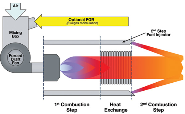
FIGURE 4. The first step in the fuel-injection method involves high excess air and heat transfer
In the second step of the combustion process, additional fuels are injected into the combustion products. For this to be effective, some amount of heat must be removed prior to the first step and before subjecting the second step to fuel. The heat generally can be removed by a radiant heat exchanger to the furnace walls.
During the first step, the combustion reduced to flame temperature between the heat exchanger is insufficient. FGR can be added to the first-step combustion to reduce the flame temperature itself. The fuel injected in the second step may be staged to blend it with furnace gases and fuel station of the second fuel injection step, which is common for this system.
The typical packaged boiler using a two-step fuel-injection system achieves around 30 ppm NOx without FGR. If FGR is added to the two-stage injection process, NOx can be reduced to 9–10 ppm.
Applying the two-step air injection method to very large furnaces, such as field-erected boilers, requires two combustion systems because of the sheer volume required.
In the air-injection method (Figure 5), the first step is a very rich, or what is called sub-stoichiometric, combustion. In this type of combustion, there will be only partial combustion in the first step.
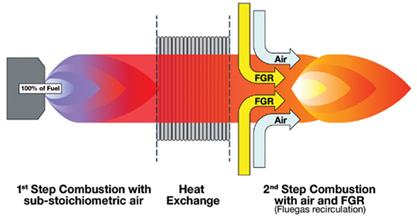
FIGURE 5. The air-injection method begins with sub-stoichiometric combustion
In the second step, the rest of the combustion air is introduced, and usually the heat transfer between the two injection steps is not sufficient to reduce the temperature. Therefore, FGR has to be introduced in the second injection step along with air.
The second combustion step is responsible for most of the thermal NOx production, so it is important to control the temperature of the flame. In the field, this is often referred to as over-fire air on field-erected boilers. By utilizing the two-step air-injection method, NOx can be reduced to 30 ppm. With Number 6 oil (a high-Btu-content residual oil), NOx can be reduced to 140 ppm, whereas it normally would be around 375 ppm.
Advanced controls
To utilize these combustion technologies or processes, advanced controls, such as parallel positioning systems or fully metered systems, are required. Additional options include variable speed drives (VSD) and O 2 trim airflow-trimming systems (described in the upcoming section). These systems provide precise control, which is needed to control the fuel-to-air ratio and achieve a good mixture with the firing technologies.
Parallel positioning. Basically, parallel positioning is a control system that optimizes the burner’s fuel-to-air ratio. There are many benefits of utilizing a parallel positioning system instead of a standard, single-point position.
Parallel positioning provides precise fuel-and-air ratio control because there is an actuator directly coupled to the control valve, whether it be the air damper, gas metering valve or FGR valve to ensure repeatability. At all points in the combustion process, it is always going to repeat.
Parallel positioning utilizes dedicated servos that are high-resolution actuators, and each one of the fuels or air has its own dedicated servo. The air damper has its own dedicated servo. The gas control valve has its own dedicated servo, and if FGR is present, there is a servo on the FGR valve that will control the amount of recirculation. Every actuator is also equipped with a feedback signal to improve safety. If an actuator does not reach its position, it will signal an alarm and shut down.
Each of these can have its own separate curve that will be applied. The air-fuel curve for parallel positioning is a software function. Because of that, it is possible to modify a curve or even have multiple curves for the fuels to meet the requirements for the various burner technologies. Also, because it is a software function, there is the capability of adding a variable-frequency drive (VFD), VFD bypass and O2 trim systems.
Since high-resolution actuators are used, there is good combustion throughout the entire modulating process of the burner. And, a big benefit is there is less hysteresis loss. Because of this, expect fuel savings of about 2 to 3%. This fuel savings means less fuel is being burned, which translates to fewer emissions going into the atmosphere.
By utilizing an advanced control with a newer combustion firing technology, NOx emissions can be reduced to 9 ppm or, in some cases, as low as 5 ppm.
Fully metered systems. A fully metered system is the preferred method used to accommodate air and fuel pressure or temperature changes in a firing-rate control system. To graduate from a parallel positioning system is to go to a fully metered system with cross-limiting capabilities (Figure 6).
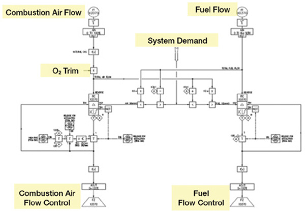
FIGURE 6. This fully metered control system includes cross-limiting capabilities and individual device actuators
Similar to a parallel positioning system, a fully metered system uses individual device actuators. The primary operational difference is that a parallel positioning system uses the position of the air- and fuel-control devices as indications of proper flow, and a fully metered system uses flow sensors to monitor the actual air and gas fuels flow. Additionally, while it is monitoring, a fully metered system will adjust the control devices as necessary to achieve the desired flow.
A fully metered system is used to create the air and fuel setpoints against which the respective flows are prepared to create the flow control position air signals. Using an O2 trim system is highly recommended with this type of system.
A fully metered system with a cross-limiting firing control has the highest efficiency and best emissions control of all the systems in use today, because it comes with air and fuel meters enabling flow indication and totalization.
In addition, a fully metered system has the potential for pressure and temperature compensation. It also is compatible with multiple-burner applications and alternative fuels. It can do simultaneous firing with different types of fuels safely, efficiently and reliably. Both federal and local regulations often require fuel totalizers, and this fuel metering system includes those.
O2 trim. O2 trim is an option that maintains excess air at a desired level in a combustion system. It compensates for small variations in the fuel-to-air ratio caused by operating conditions. Variations include atmospheric pressure changes, temperature changes, or just mechanical wear and tear of the burner and components themselves.
Remember, one thing about burner combustion is that anything that can impact air or fuel flow will impact burner performance, which negatively impacts emissions.
The O2 trim option requires an O2 sensor that is installed in the fluegas outlet, up in the stack of the boiler. It gives a feedback signal to the combustion control system.
The system maintains the optimal O2 combustion to achieve NOx targets with good, complete combustion. This is both a performance factor and safety factor. Having O2 trim prevents the combustion from getting too rich or falling below 1% O2. On some burners, it is critical to not exceed 8–9% O2 during combustion.
O2 trim is also a very effective way to identify a potential problem. If O2 levels start increasing, O2 trim systems will reveal it.
Additional benefits of O2 trim are efficiency and reliability. Basically, the control ensures fluegas O2 consistency, better combustion and fuel-air corrections in conjunction with air temperature changes, all of which result in fuel savings of about 2–3%.
VSD. Another option is installing a variable speed drive (VSD) on the fan that improves the ability to control combustion air, especially if the fan is oversized. With better air control, there is more control of the fuel-air ratio, which translates into better, more accurate, more efficient combustion. And, by doing that, low and ultra-low NOx emissions can be achieved.
Post-treatment solutions
A selective catalytic reduction (SCR) system can help reduce NOx emissions by as much as 94%. For instance, if a facility has an uncontrolled burner with 100 ppm NOx, an SCR system can reduce emissions to 6 ppm NOx. Another benefit with SCR systems is that by utilizing some of the burner technologies above, less catalyst is required.
On a 30-ppm burner, 5–6 ppm NOx is achievable with SCR, while using less of the catalyst. This solution works with any fuel if the fluegas temperature is within the 400–700ºF range. In this temperature range, the catalyst exhibits its highest level of activity. The catalyst bed can be designed for small to very large exhaust flowrates of millions of columns per hour, and ammonia injection can be varied to accommodate various fuels for multiple-fuel- and simultaneous-firing applications.
Note that there are a couple of limitations with SCR. One is that fluegas flow cannot contain too much particulate matter. Otherwise, the catalyst will plug up quickly. There are different catalyst pitches that can be used to mitigate this problem. Also, the catalyst can be deactivated in the presence of certain substances, such as catalyst poisons.
Also, because ammonia is a base, the fluegas acid concentration must be monitored closely on this type of system. Below the acid dewpoint, ammonia will combine with an acid to form a salt, which can plug the catalyst itself. Figure 7 illustrates how an SCR system works to reduce emissions and NOx.
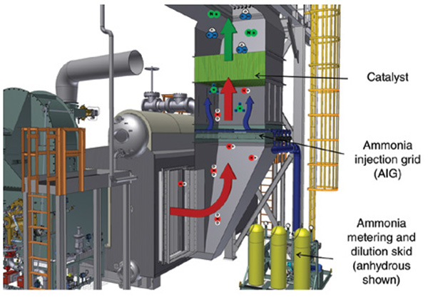
FIGURE 7. A selective catalytic reduction (SCR) system is used to further reduce emissions downstream of combustion processes
In an SCR system, the reaction to ammonia with NOx will occur naturally at high temperatures, around 1,600˚F. This reaction decomposes the NOx, NO and NO2 into harmless water and nitrogen gases.
The introduction of ammonia in the boiler system adds a new emission that has to be contained — ammonia slip. This is the unreacted ammonia that finds its way through the SCR system.
Stack ammonia slip limits are usually between 2 and 10 ppm. Because of the slip limit, the ammonia flowrate needs to be precisely controlled to match NOx flowrate. This function is controlled by an ammonia flow-control unit. Also, to minimize ammonia slip, the ammonia injection pattern needs to match that of the NOx distribution pattern.
This function of the ammonia is part of the ammonia injection grid. As the exhaust gas flows through, the ammonia flow-control monitors the amount of ammonia going into the ammonia injection-grid area. Inside, it is mixing with the exhaust gases, going through and out of the catalyst. Again, with SCR, N2 and H2O are the byproducts.
The future of combustion
The boiler industry will continue to strive to decrease NOx emissions. In addition to reducing NOx emissions, there is emphasis on reducing the carbon footprint.
In the near future, look for technologies to be implemented within these combustion cycles to not only reduce NOx emissions, but also to reduce the amount of carbon output from the combustion process. Carbon-capture systems and other technologies are gaining more traction.
Another focus for our industry is energy efficiency. Higher efficiency equipment utilizes heat better, which naturally reduces the amount of fuel needed to be burned, and hence, emissions (Figure 8).
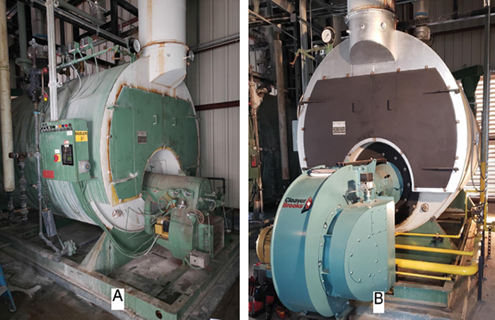
FIGURE 8. Replacing a legacy burner (A) with a new low-NOx burner (B) helped this plant to reduce NOx emissions from 90 down to 24 ppm. Also, cycling and excess air were reduced, increasing overall efficiency and reducing fuel usage by 10%
Lastly, there is also big focus on engineered and renewable fuels, especially on the hydronics side. Renewable fuels have less emissions byproduct, which is helping many companies today achieve their targeted sustainability goals. ■
Further reading
1. Achieving Balance in Combustion, Chem. Eng., August 2022, pp. 14–17.
2. New Ways to Achieve Better Control of Emissions, Chem. Eng., January 2021, pp. 12–15.
3. Low-Cost Techniques for NOx Reduction, Chem. Eng., May 2020, pp. 30–36.
4. Enclosed Combustion Equipment and Technology, Chem. Eng., January 2018, pp. 46–49.
Author
Jonathan Stoeger is an inside sales and application manager, for the Burner Systems Group of Cleaver-Brooks (221 Law St; Thomasville, GA 31792; Email: [email protected]; Website: www.cleaverbrooks.com). He has been with Cleaver-Brooks for 17 years, and has served on the ASME’s CSD-1 Code committee (Controls & Safety Devices for Automatically Fired Boilers), and is currently an alternate member of the committee. Stoeger holds a degree in mechanical engineering from the University of Wisconsin-Platteville.