The continuing development of natural gas extraction from shale deposits, known simply as shale gas, is fueling the growth of simple- and combined-cycle power plants. Much coal-fired power is being replaced by these technologies. In addition, though, simple- and combined-cycle units are well suited for power and steam production at industrial facilities.
The combustion turbine
Back in the heyday of large power-plant construction, primarily from the 1950s through the 1970s, the most popular technologies were complex coal-fired or nuclear facilities, with hydro power providing much of the remainder. Concerns regarding nuclear safety, global climate change, and quite frankly, cost, have led to movement away from large steam generators to smaller units, and in many cases decentralized power. This includes chemical process industries (CPI) and other manufacturing facilities that produce process steam and at least some of their own power, rather than relying solely on electricity from utilities.
 |
|
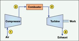
Figure 1. This schematic shows the basics of a combustion turbine
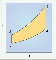
that follow the four steps of the Brayton cycle (shown in Figure 2) |
 |
The core of many modern systems is the combustion turbine (CT), a simplified outline of which is shown in Figure 1.
A CT operates similarly to a jet engine via the following steps, which are part of a fundamental thermodynamic cycle, the Brayton Cycle (Figure 2).
1. Inlet air is compressed and injected into the turbine. The compressor is attached to the turbine shaft, and thus the compressor and turbine rotate in unison
2. Fuel, typically natural gas but occasionally fuel oil, is injected and ignited in the compressed air stream
3. The expanding gas drives the turbine
4. Hot exhaust, at 850°F or higher, exits the turbine
Like other energy-producing devices, most CTs are equipped with auxiliary features to improve efficiency, and we will examine some of these later in this article. For the time being, key points of a combustion turbine include very fast start times, low capital cost as compared to coal or nuclear, simplicity of fuel feed and minimal operations and maintenance issues. These benefits are quite important in the power industry, especially the fast start times during peak power periods when demand skyrockets. However, for industrial processes with continuous steam and electrical requirements, steady and efficient operation is required. Enter the combined-cycle plant.
The combined-cycle
The downside to simple-cycle operation is that the turbines are only about 35% efficient. Much energy escapes with the turbine exhaust. This is where the combined-cycle design, of which many readers are undoubtedly familiar, shines forth.
With combined-cycle, a heat recovery steam generator (HRSG) is placed at the exhaust of the combustion turbine or turbines to utilize the exhaust heat for steam production. While many HRSG designs are available, the most common is the multi-pressure, drum-type unit as depicted in Figure 3.
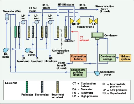
In this particular design, the condensate is split between the circuits, with a relatively small flow to the low-pressure (LP) steam network and the bulk of the flow to the intermediate-pressure (IP) and high-pressure (HP) circuits. Steam extraction may be taken from any of the circuits, or, as is most efficient, from a non-condensing turbine. A less complex scenario that may be better for cogeneration applications is a combustion turbine with a single-pressure HRSG perhaps without a steam turbine, where the HRSG operation is less complex than with multi-pressure units. For example, a colleague and I recently prepared the water balance for a proposed power project in which one scenario called for two combined-cycle units, one with a CT and a three-pressure HRSG, and the other with a CT and a single-pressure HRSG that partly supplies steam for power augmentation. This example illustrates the flexibility that is possible with combined-cycle generation.
Net efficiencies of combined-cycle units for power production have closed in on 60%, while up to 80% efficiency is possible for co-generation. However, capacity and efficiency are greatly influenced by inlet air conditions — temperature foremost — but also humidity.
Maximizing capacity output
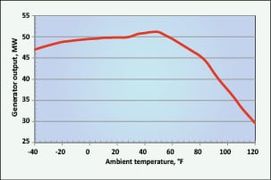
Figure 4 illustrates what happens to aeroderivative combustion-turbine capacity with increasing ambient air temperatures. Similar effects occur in larger frame units, albeit without a subcooling loss of efficiency.
To this point in time, the two most common methods for turbine inlet-air cooling have been mechanical chilling or water-fed evaporative cooling. With the former, parasitic power load may be in the 1 to 3 MW range. Evaporative coolers on the other hand, as their name implies, chill inlet air by evaporation of water spread upon an inlet media. Water requirements for these coolers may range from 30 to 80 gal/min. Also, evaporative coolers can only provide chilling down to a fixed approach to wet-bulb temperature.
A third method is gaining interest, absorption refrigeration turbine inlet air conditioning (ARCTIC), which mitigates or eliminates both parasitic power consumption and water requirement issues, while offering precise control over inlet air temperatures. Such control can be quite important for plants based in hot or humid environments. ARCTIC technology uses the extremely well-known process of closed-cycle, ammonia-based absorption refrigeration, with turbine exhaust heat as the energy source.
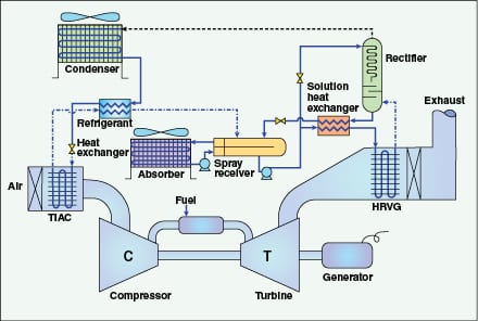
Figure 5 outlines the general flow schematic for ARCTIC technology. The process relies upon classic thermodynamic refrigeration. The turbine exhaust warms an aqueous ammonia solution in heat exchanger coils (HRVG on the diagram) located within the exhaust-gas path. The ammonia is then separated in the rectifier to produce a nearly pure vapor, which is condensed, reduced in pressure, and then allowed to expand within turbine inlet air-cooling coils (TIAC) located in the inlet air stream. The pure ammonia discharge from the cooling coils is blended with the aqueous ammonia bottoms product from the rectifier (a process that requires additional heat exchangers due to the exothermic reaction), and is re-pressurized for return to the HRVG. Thus, the process is a closed loop, with all equipment but the TIAC and HRVG coils located on a single skid.
A standard skid-mounted cooling unit can provide over 2,000 tons of chilling at 220 kW of auxiliary load. The parasitic power load for a mechanical compressor to provide similar chilling ranges from 1.6 to 3.2 MW. During one summer day in 2011 at a plant in the southwestern U.S., an ARCTIC system maintained an inlet air temperature of 48°F (5°C) when the ambient temperature was 107°F (42°C). An added feature of this process, and one that is gaining interest in arid climates, is that cooling coils may be placed downstream of the HRVG to recover water from the fluegas. As is well known, the combustion process, and particularly that from gas turbines, produces a significant quantity of water due to the reaction of hydrogen in the methane fuel with oxygen.
CH4 + 2O2 → CO2 + 2H2O
Recovery of fluegas moisture can potentially turn some plants from fresh water consumers to water producers. As an example, consider a combustion turbine fired with natural gas at a fuel flowrate of 87,000 lb/h. We will use three simplifying assumptions:
• Natural gas composition is 100% methane (CH4)
• Complete combustion is achieved in the turbine
• The process recovers 100% of the water produced by combustion
Stoichiometric calculations show a water recovery rate of 390 gal/min. Given that natural gas is typically a very clean fuel, the recovered water could easily be returned to the inlet of the plant makeup-water system or to other processes. An obviously important issue with fluegas water recovery is the effect that chilling would have on the buoyancy of the fluegas stream, and in turn, how this might influence fan design and air-permitting issues.
In addition to inlet air cooling, other techniques are available for maximizing power during peak-load conditions. One method, whose primary purpose is to control of oxides of nitrogen (NOx) formation, is injection of demineralized water into the turbine. The demineralized water lowers the combustion temperature, which is the driving force for NOx formation. But, the water adds mass to the combustion gases and improves capacity, albeit at a bit of an efficiency penalty. Another option that I have seen in a few recent power applications is steam injection to the combustion turbine. This process is primarily utilized for power augmentation (PAG) when an extra few megawatts are needed from the plant. One drawback to PAG and water injection for NOx control is that extra makeup water is necessary to produce the fluids for turbine injection. This requirement can increase the size of makeup-water treatment equipment or demineralized water storage capacity. The reader will note that I have emphasized demineralized water for these applications, as anything of lower quality injected into the combustion turbine would cause fouling and corrosion.
Don’t neglect HRSG chemistry
In 2008, I discussed the importance of maintaining proper chemistry in CPI steam generators during regular operation and times of shutdown [ 2]. These principles also apply to heat recovery steam generators. The following list sums up many of the most important details of steam generator chemistry that have evolved over the past decades, and particularly within the past 20 years:
• Even seemingly minor contaminant in-leakage to condensates can result in major problems, most notably steam-generator tube failures that cause unit shutdowns
• For systems with water-cooled steam condensers, the condenser can be the most dramatic source of contaminant in-leakage. Impurity introduction via a condenser-tube leak has been known to cause boiler tube failures within weeks, and sometimes even days or hours
• Too often at CPI or other manufacturing plants, insufficient attention is given to condensate return from process equipment to the steam generator. The impurities introduced by contaminated condensate may be as harmful as those introduced by condenser tube leaks. Condensate recovery can be quite cost effective, but only if it is properly treated to prevent boiler contamination. Treatment may include filtration, ion exchange, or other techniques
• Unless the condensate/feedwater system of a high-pressure steam generator contains copper alloys, the use of oxygen scavengers is highly discouraged. These are now known to propagate flow-accelerated corrosion (FAC) in feedwater systems, economizers, and the low-pressure evaporator of HRSGs, among other locations (for more, see Chem. Eng.; March 2013, pp. 38–40). FAC-induced failures have caused a number of fatalities at power plants in the last 25 years. The same phenomenon will occur in CPI steam generators
• The most common treatment for IP and HP circuits in HRSGs is the program known as phosphate continuum, and most commonly at the low end of a 1 to 10 parts-per-million (ppm) phosphate range. This program was developed by the Electric Power Research Institute in response to problems with earlier phosphate programs, and calls for the use of only tri-sodium phosphate with perhaps a slight amount of caustic at startup. Alternatives include straight caustic treatment (at less than 1 ppm free sodium hydroxide) and all-volatile treatment, where only the ammonia or amine utilized for feedwater pH control provides the treatment for the steam-generator circuits
• For all of the above items, accurate and reliable online monitoring systems need to be in place to detect upsets. Operators of the steam generator must be properly trained to recognize off-specification conditions
• Improper boiler layup can cause excessive corrosion that not only damages components but generates massive amounts of corrosion products that travel to the steam generator and deposit on boiler tube surfaces. Under-deposit corrosion via several possible mechanisms is a primary cause of boiler-tube failures. Ideally, for short-term shutdowns where water is left in the steam generator, nitrogen blanketing can be utilized to protect the system from air in-leakage. If nitrogen blanketing is not an option, then other wet lay-up procedures should be established. Also, very reliable technologies now exist to remove dissolved oxygen from steam generator fill water. This is an important issue, particularly for units that face frequent shutdowns and layups, and where demineralized water and condensate are stored in atmospherically vented tanks [ 3]
Readers who are interested in learning more about steam-generator makeup-water treatment, chemistry, and layup issues are encouraged to attend the annual Electric Utility Chemistry Workshop (www.conferences.illinois.edu/eucw).
References
1. Buecker, B., Steam Generation Thermodynamics, Chem.Eng., November 2010, pp. 44–47.
2. Buecker, B., CPI Water and Steam Chemistry; Chem.Eng., February 2008, pp. 30–34.
2. Buecker, B., and Dixon, D., Combined-cycle HRSG Shutdown, Layup and Startup Chemistry Control, Power Engineering, August 2012, pp. 64–68.
Author

Brad Buecker is a process specialist with Kiewit Power Engineers (9401 Renner Blvd., Lenexa, KS 66219; Phone: 913-928-7000; Fax: 913-689-4000; Email: brad.buecker@kiewit.com). He has over 30 years of experience in, or affiliated with, the power industry, much of it in chemistry, water treatment, air quality control, and results engineering positions with City Water, Light & Power in Springfield, Ill., and Kansas City Power & Light Company’s La Cygne, Kan., station. He has an A.A. in pre-engineering from Springfield College in Illinois and a B.S. in chemistry from Iowa State University. He has written many articles and three books on steam generation topics. He is a member of the ACS, AIChE, ASME, CTI, and NACE. Buecker is also a member of the ASME Research Committee on Power Plant & Environmental Chemistry, the program planning committee for the Electric Utility Chemistry Workshop, and the program planning committee for Coal-Gen.