Comprehensive planning, along with appropriate level-measurement technologies and safety instrumented systems, can empower plant personnel to significantly reduce the likelihood and severity of hazardous chemical spills
In most industries that manufacture, use or store chemicals and other hazardous liquids, a spill prevention, control and countermeasure (SPCC) plan is required to operate storage tanks. Even when not mandated, an SPCC plan can help prevent damage to facilities, contamination of the environment and injury to personnel.
An SPCC plan is designed to prevent spills from occurring — and control them when they do — by deploying countermeasures to mitigate the damage and extent of a spill. This usually begins with installing or upgrading level instrumentation throughout a facility.
Chemical spills are most frequently caused by tank overfill or process leaks. While preparatory prevention is the goal, the possibility for incidents is never zero. This article covers prevention and detection measures for overfill and leak events, as well as instrumentation-specific requirements to accomplish these tasks.
Overfill prevention specification
Overfill prevention of chemical storage tanks is best implemented by combining radar — or another continuous level-monitoring technology — with point-level switches. With such a setup, the continuous level-monitoring instrument provides a process parameter for use by the primary control system, while at least one point-level switch is dedicated to an isolated safety instrumented system (SIS).
Industry best practice for managing tanks combines existing prescriptive standards from the American Petroleum Institute (API; Washington, D.C.; www.api.org), such as API 2350, with functional safety standards from the International Electrotechnical Commission (IEC; Geneva, Switzerland; www.iec.ch), such as IEC 61511. The API 2350 specification can be met by using a SIS designed in accordance with IEC 61511. API 2350 prescribes methods for preventing both automated and manual tank overfills, and achieving its requirements dictates implementing a risk assessment system. Both IEC 61511 and API 2350 require proof-testing of device-safety functions at regular intervals to demonstrate SIS functionality in relation to safety requirements. This includes checking all relevant safety devices, such as level switches, signal horns and flashing beacons.
When implementing a SIS, users have the option to use pre-engineered systems or create customized configurations, depending on their specific site needs. While not a fit for every application, a pre-engineered SIS significantly eases testing efforts and reduces costs by providing users with the ability to execute systemwide proof tests with the press of a button during commissioning and operation, and throughout equipment lifecycles. This can reduce the time it takes to proof-test a tank farm’s SIS to minutes, rather than hours or days.
To meet standards and ensure safe functionality, a SIS must be independent of all other facility control systems. Every equipment element — including level and temperature control and alarming devices — must be dedicated exclusively to the SIS.
High-level overfill prevention switches, like vibrating tuning forks, provide indication when the material in a tank reaches a dangerously high point. This instrument is often referred to as a high-high level switch because it is mounted above the high-level switch used to indicate the normal fill stop point. If a high-level switch or the filling control system fails, the high-high level switch prompts an alarm system to notify personnel of overfill (Figure 1).
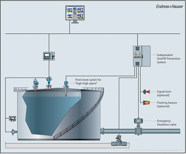
FIGURE 1. A typical overfill-prevention system requires high-high level detection in a safety instrumented system (SIS) isolated from the primary tank-gauging control system
Because high-high level switches are mounted above normal maximum fill points, years can pass without activation. For this reason, testing these switches regularly is critical to verify functionality so they work correctly when dangerous overfilling situations arise. These regular tests should be part of any SPCC plan.
Reduce risk
While testing high-high level switches regularly is required to maintain overfill SIS protection, elevating a process to an unsafe level to test these switches is not permitted under API 2350 for aboveground storage tanks.
Most facilities resort to removing switches from tanks for testing. In these cases, operators typically perform bucket tests, immersing a switch in its process liquid to ensure it works properly. Removing a switch for testing incurs the risks of downtime, lost production and potential chemical exposure for personnel. Additionally, personnel must be available to remove the switch, perform the test and reinstall the switch.
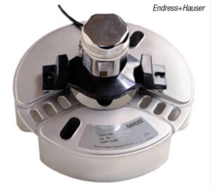
This method has additional drawbacks because removing and reinstalling switches subjects them to potential damage. They may not work correctly when reinstalled, negating a test. For these reasons, it is better to use point-level switches that support in-situ testing for critical safety-related applications (Figure 2).
FIGURE 2. This level switch supports automated in-situ self-testing for critical safety applications
Some plants rely on continuous level technologies, such as free-space radar, guided-wave radar and ultrasonic transmitters to provide overfill prevention with the assumption that continuous level measurement will provide an alert when conditions go awry. However, this thinking fails to consider process occurrences, such as foam, condensation, product buildup and other issues, which can create false readings.
For this reason, point measurement is better suited for detecting high-high levels to prevent accidental overfill and associated spills, rather than continuous level-monitoring instrumentation.
Many switch technologies for high-high overfill-prevention applications exist, including vibrating tuning forks, capacitance, ultrasonic gap switches, float switches and more. Engineers must carefully consider the best instrumentation options for each application, selecting equipment fit to tank geometries, liquids in use and industry accuracy and testing requirements.
Even the best overfill-prevention plan can go wrong, resulting in a spill. Furthermore, not only tanks can experience leaks, but also pumps, pipes, valves and fittings. When any of these adverse events occurs, rapid detection can greatly mitigate the chemical volume released and associated damage.
Application example
Combined vibronic and conductive level-sensing technologies can identify the presence and types of liquids in sumps and dikes
Installed in a drainage sump pit near a tank or pump yard, an oil-leak detector float sensor provides leak detection of petrochemicals, vegetable oils and more. Such a sensor combines vibronic and conductive technologies with dual-level logic to distinguish the presence of specific fluids for effective leak monitoring.
The conductive probe detects water-based liquids, while the vibronic tuning fork confirms the presence of oil or air. Equipped with process diagnostics, these instruments transmit status data if a cable fails or liquid freezes, assuring failsafe operation.
Advanced monitoring software works together with advanced instrumentation by executing algorithms that generate notifications when detecting anomalies or certain conditions. For example, software can notify operators of a high rate-of-change in a tank level, signaling a process issue that requires attention. ❑
Leak detection and prevention
Chemical leaks can wreak catastrophic consequences extremely quickly, and the best method to mitigate damage is to prevent their occurrence or, at the very least, expediently detect them. Doing so requires proactive measurement. Level instrumentation can safely and reliably monitor the contents of a tank, annunciating an alarm in the event of an overfill event or leak.
As the first line of defense in tank leak detection, a continuous level instrument must always identify tank-level fluctuations. If a tank level ever decreases when its associated control system is not actively lowering it, this signals the presence of a leak, and the monitoring system must notify plant staff. Demonstrating the criticality of detail in level measurement, an unexpected drop in level of just 1/8 in. in a 30-ft diameter storage tank — a common size at petrochemical facilities — represents over 60 gal of fluid leaked. As a result, accuracy must be measured in fractions of millimeters. Many radar level gages can provide accuracy of 0.5 mm (Figure 3).
FIGURE 3. Since very small changes in level can translate to large fluid losses, radar level transmitters should be able to detect tank levels within an accuracy span of less than 1 mm
For many hydrocarbons and chemicals, tank instrumentation must also incorporate temperature compensation, because chemical volume expands and contracts with temperature changes. These volumetric fluctuations cause levels to change, even when no fluid escapes or enters a tank. Temperature sensors with multiple measurement points and high-precision accuracy are required for such applications.
Monitoring level measurement with a software system is the best way to determine when level changes should and should not be occurring. When the level drops at a time it should be stable or rising, the system must alert facility personnel of a possible leak or spill.
Monitor the dike
The second line of leak-detection defense is equipping level switches inside retention dikes. All accumulation, including rainwater after a storm, must be removed to maintain dike availability for catching spills or leaks. Level switches to reliably indicate any liquid, such as tuning forks, are best suited for this application.
There are many specialty instruments that indicate the presence of liquid and its conductive properties. This helps identify the liquid to distinguish whether it is rainwater (conductive) or a hydrocarbon (nonconductive). By combining a vibrating tuning fork, which detects liquid regardless of its conductivity, and a conductivity switch, facility personnel and software systems can identify the type of accumulation in the dike.
When the dike is empty of all liquid, neither the tuning fork nor the conductivity switch report any liquid. When the dike is full of water, both the tuning fork and the conductivity switch report liquid presence, assuming the water is conductive, as is typically the case with rainwater. When the dike contains a nonconductive liquid, the tuning fork reports presence of a liquid, but the conductivity switch does not, indicating a spill or leak of a nonconductive chemical.
Maintenance is key
Accurate instrumentation is the cornerstone for any safety system’s reliability. One of the greatest challenges in maintaining instrumentation reliability is a lack of awareness when issues arise.
Many modern instruments, particularly smart instruments, transmit process and device diagnostics, in addition to primary process variables. By monitoring these diagnostic data at central processing points and implementing notifications, control systems can alert operators of automatically detected instrumentation issues, identified directly by the instruments (Figure 4).
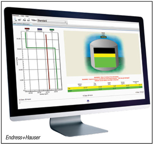
FIGURE 4. Computer-based tank monitoring tools can promptly alert operators of diagnostic and process issues to minimize plant disruption
Diagnostic information is useful for implementing predictive maintenance programs because instrumentation usually begins to register issues prior to complete failure. This can help maintenance staff focus their efforts where most needed, reducing unplanned downtime, along with unnecessary and costly instrument replacement.
Incident response
The more quickly a SIS can identify chemical spills and leaks, the better a facility can control incidents and respond appropriately. The right level instrumentation can provide early indication of issues, and then dispatch alerts to mitigate risk. When an incident occurs, a well defined response can make the difference between acceptable recovery and catastrophic harm to equipment, the environment or humans.
This requires creating a response plan and frequently training personnel. The plan involves assessing the risk each storage tank presents, incorporating its chemical contents, volume and the potential damage a spill or leak could cause. Planners should consider the many types of hazards and events that can occur, creating procedures to handle these permutations, so personnel know exactly what equipment and safety measures are at their disposal to mitigate incidents.
Available equipment includes spill clean-up products, floating dikes, absorption material, emergency pumps, safe storage tanks and more. In addition to facility personnel, most industries specify regional emergency groups and authorities who must be notified when spill events occur. A well-planned and well-practiced response plan limits the damage, reducing consequences.
Tank-inventory management software can help by detecting leaks and spills, directing emergency procedures (such as shutting off pumps), alerting personnel and documenting the spill.
Executing the SPCC plan
A sound SPCC plan greatly reduces the likelihood and severity of chemical spills and leaks. Proper instrument selection for overfill prevention provides the best solution to prevent spills, along with frequent testing to ensure equipment functions properly when needed. By implementing smart instruments and software monitoring, it becomes easier to monitor level changes and other process conditions, providing timely alerts of leaks and minor spills.
Retention dike monitoring helps signal the presence of an issue and identifies the type of liquid leaked. Prompt notification of a leak or spill enables rapid response, and comprehensive response plans and training reduce the severity of incident damage to a minimum. ■
Edited by Mary Page Bailey
Authors
 Howard Siew is the chemical industry manager at Endress+Hauser USA (2350 Endress Pl, Greenwood, IN 46143; Phone: 888-363-7377; Email: info.us.sc@endress.com). He is responsible for the overall business development and growth of the company position related to the chemical industry. Siew is a chemical engineering graduate from Louisiana State University, and he is TÜV certified as a functional safety engineer in SIS. In addition, he participates in the ISA84 working group where he contributes expertise and gains an understanding of the latest industry standards to advise customers and colleagues.
 Brian Howsare is the International Inventory Management Solutions (IMS) business development manager for Endress+Hauser (same address as above). He has been in the process instrumentation industry since 1984 and has been with Endress+ Hauser since 2001. With Endress+Hauser, he has held several positions, including level and digital communication specialist, certified Profibus engineer and technical sales and solutions business manager. In his current role, he works closely with terminals, tank gauging systems, inventory control and the industrial internet of things, using wireless and cellular remote monitoring instruments and gateways.