Distillation is one of the most extensively used operations in the chemical process industries (CPI). It is a highly energy-intensive unit operation, and continuously rising energy costs make it imperative to look for ways to reduce energy requirements. Some energy-saving configurations can increase capital investment costs, so the benefits need to be weighed carefully. Various techniques, such as heat integration, heat pumps, thermal couplings and others have been employed to achieve energy reductions [ 2–4]. Vapor-recompression-assisted distillation is one such technique to reduce energy consumption by utilizing the energy from the column overhead stream, with added external mechanical energy, to boil the bottom stream.
This article illustrates the technique through an example of a typical C3-splitter (propane-propylene splitter) design wherein significant energy savings and operational benefits are achieved by using vapor recompression distillation. With the availability of reliable and proven compressors to handle large capacities for industrial use, this concept is gaining attention and merits consideration for new distillation installations.
The basics
Conventional distillation columns have a separate reboiler and a separate condenser. A vapor-recompression-assisted column has a combined “condenser-reboiler”. The basic feature of a vapor-recompression distillation system is utilization of the heat content of the column’s overhead vapor to supply heat required in the reboiler. The temperature driving force required to force heat to flow from cooler overhead vapors to hotter bottoms product is provided by compressing the overhead vapor. In such a system, column overhead vapor is first sent to a compressor to raise its pressure and temperature. Heat content of this compressed overhead-vapor stream is then utilized for providing vaporization duty of the reboiler. While giving heat to the bottoms reboiler, the overhead vapor is condensed, and part of it is returned to the column as reflux. Figure 1 shows a schematic arrangement of both conventional and vapor-recompression types of distillation for a typical C3-splitter column.
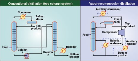
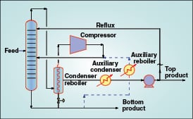
As shown in Figure 1, a conventional C3-splitter column is split into two separate columns due to practical construction limitations on the height of a single column. Vapor recompression distillation for the same application, however, has only one column with a common reboiler-condenser. A flash tank is added to the flowsheet to avoid the return of flashing reflux back to the column. An alternate configuration for vapor recompression distillation consists of compressing the reboiler outlet vapors instead of column overhead vapors. As shown in Figure 2, this configuration includes lowering the pressure on reboiler liquid so that it boils at a lower temperature, and then compressing the bottoms vapor back to the column pressure. In either case, an auxiliary condenser or an auxiliary reboiler may be required if the column reboiling and condensing heat duties do not match exactly.
For many conventional distillation systems, the column operating pressures are dictated by limitations of either heating- or cooling-media temperatures. In these cases, it is not possible to operate the column at lower pressures to take full advantage of the relative volatility factor. This imposes a constraint on optimization and thus on energy requirements. On the other hand, vapor-recompression-assisted distillation columns can be optimized for lower-pressure operation. The vapor recompression concept is generally applied to close-boiling super fractionator systems due to small temperature differences between condensing and reboiling temperatures [ 1]. If the temperature difference is large, it may result in an uneconomical amount of external work to be added — keep in mind that electricity costs are typically much higher than the costs of other utilities, such as steam or cooling water. Thus, the typical application area for this concept is mainly in the separation of close-boiling mixtures.
There are a number of additional advantages associated with vapor recompression systems. First, a large amount of heat can be moved between the condenser and reboiler with a relatively small work input. This results in overall energy savings. Operating pressures of a vapor-recompression-assisted column can be set where desired to achieve the maximum separation, and are not governed by the cooling- and heating-media utilities available. For close-boiling-point systems the result is significant since relative volatility is improved at lower pressures and separation becomes easier, thus reducing the column height and/or reflux requirements.
C3-splitter design case study
Using the basic concepts outlined above, a process optimization case study is presented to demonstrate energy savings achieved by employing a vapor recompression scheme for a C3-splitter column. To illustrate the benefits, energy requirements are compared with a conventional system.
The C3-splitter column is used for separation of propane and propylene to obtain polymer-grade propylene. This is a commonly encountered industrial separation process. Conventional distillation consists of a single column (typically split into two columns due to height limitations, and connected with a pump for internal, liquid traffic flow) with a steam-heated reboiler and water-cooled overhead condenser. The vapor-recompression-assisted distillation consists of an overhead vapor compressor, common reboiler-condenser and an auxiliary condenser. Table 1 gives details for the feed conditions, product specifications and utilities used for the distillation column designs. In a fluid catalytic cracking (FCC) unit of a petroleum refinery, the C3-splitter column is installed downstream of a de-ethanizer column. Hence, the feed stream to the C3 splitter essentially contains propane and propylene with negligible amounts of other components. Therefore, for simplicity, a binary system is considered. For simulation and other comparisons, the feed and product purity as well as recovery are kept the same for both the conventional and vapor-recompression cases.
The simulation model
Rigorous simulations were developed using steady-state simulation software. The thermodynamic systems are based on the Soave Redlich Kwong (SRK) equation of state. The built-in convergence method for distillation models is Russel’s “Inside Out” routine [ 6] converging on error tolerance between inner simple loop and outer rigorous loop. Initial estimates are obtained from the shortcut distillation module, which uses the Fenske method to compute minimum trays required and the Underwood method for computing the minimum reflux ratio [ 7].
Conventional column simulation.Thermodynamically, it is desirable to operate the column at a pressure as low as possible for better separation. However, column pressure is also governed by the available utilities. A circulating cooling-water system used as the cold utility in this case study has a 32/38C supply/return temperature. Considering a reasonable approach of 10C for the overhead condenser design, the dew point of overhead vapors must be 42C, which corresponds to 17 kg/cm2 gage pressure. Thus, the column operating pressure is fixed at 17 kg/cm2 gage based on the constraints of the cold-utility supply temperature.
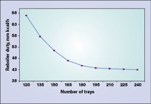
A shortcut distillation model is set up for the given feed composition and required product specifications. The shortcut distillation module uses average relative volatility for the column and calculates the minimum reflux ratio required for the desired separation using the Underwood method [7]. For a column operating at 17 kg/cm2gage pressure, the minimum reflux ratio was calculated as 10.51. A rigorous distillation model is then set up based on the results of the shortcut distillation model. An optimum reflux ratio of 1.5 to 1.6 times the minimum reflux ratio is selected. Theoretical stages are varied from 120 to 240, and the reflux ratio — which in turn is represented by reboiler duty (mm kcal/h) here — is plotted against the number of theoretical trays. The reboiler duty or the reflux ratio decreases as the number of stages increases. As it can be noted from Figure 3, there is no significant reduction in the reboiler duty beyond 180 trays, hence the number of theoretical stages is fixed at 180. Theoretical trays are numbered from the top in the simulation model.
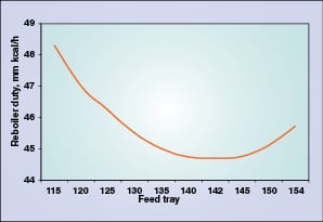
The feed tray location is selected so as to minimize reboiler and condenser duties. Figure 4 indicates that the optimum duty is achieved when the feed tray is located at tray 142. Finally, the column diameter of 6,250 mm is estimated based on a maximum of about 75% flooding. Results of the conventional column simulation are summarized in Table 2 for comparison.
Vapor-recompression-assisted column simulation. Steady-state simulators solve distillation column problems using various built-in algorithms that necessarily include reboilers and condensers as part of the distillation-column module itself. Thus, there is no need for the user to define the recycle streams (such as the reflux or vapors from the reboiler) or solve the distillation system by defining the calculation sequence manually in the simulation (using “tear stream algorithms”). When the vapor recompression system is used, the reboiler and condenser are one integrated unit (called the “common reboiler-condenser”) rather than individual units.
The reboiler temperature approach (the temperature difference between the reboiler outlet and the overhead compressed vapors entering the reboiler) is a major variable that affects compressor design. Available, standard distillation modules of simulators cannot be used in a straightforward manner. One possible way to model such a system is to use the conventional distillation-column module without the reboiler and condenser attached to it. A separate exchanger, as another flowsheet component, would then need to be selected to model the common reboiler-condenser. Also, separate flowsheet streams are required to connect the common reboiler-condenser to the distillation column. These flowsheet streams are thus not part of the column’s built-in algorithm. With this approach, the user encounters a number of convergence difficulties even after matching the tear stream (the recycle stream to solve the closed loop) estimates close to reality. Apart from the common reboiler-condenser, a compressor needs to be defined as part of the external recycle loop. The process-flowsheet model’s intrinsic recycle-loop-convergence method iterates the model until the specified heat-and-mass-balance related tolerances are achieved. Thus, convergence of the system will be highly iterative and it is also observed to diverge from the solution in each successive iteration, even if initial estimates are close to reality.
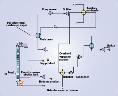
To overcome the above-stated simulation difficulties, an indirect modeling method is used [ 5]. A pseudostream is used to generate stream properties and rates for the stream leaving the top tray. This pseudostream becomes input for a standalone, sequentially executed compressor-exchanger recycle loop. The advantage of this approach is that it substitutes a recycle-stream convergence model with a once-through calculation. Multi-unit operations, such as the compressor-exchanger, can be solved independently without having any interference with the standard, distillation calculation module. Figure 5 illustrates the development of this model to define the vapor-recompression-distillation flowsheet.
Simulation of the vapor-recompression-distillation column uses the same feed conditions and meets the same product quality and recovery as given in Table 1. A main advantage to the vapor-recompression system is the possibility to operate the column with a lower operating pressure than a conventional column because cooling-water conditions no longer limit the system due to the common reboiler-condenser. The column operating pressure is dependent upon various optimization considerations.
The compressor is a key equipment item in the vapor recompression configuration. The overhead vapor stream is compressed to increase the condensing temperature to a temperature sufficiently greater than the temperature of the reboiler feed stream. Lower temperature differences increase the reboiler size, but also reduce the compression ratio and, hence, the size and power consumption of the compressor. The outlet pressure of the overhead vapor compressor is fixed, based on a reasonable 20C approach temperature in the common condenser-reboiler. The column operating pressure, which is also the compressor suction pressure, is fixed based on the optimum compression ratio. The operating pressure was thus fixed as 12 kg/cm2gage.
A further reduction in column operating pressure requires an additional compressor stage and additional capital cost. The compressor discharge pressure is such so as to obtain a discharge temperature of about 70C. Based on the heat duty requirement of the reboiler and the need to match the heat balances, the compressor discharge stream is split. Part of the stream is routed to the common reboiler-condenser and the balance is condensed in an auxiliary condenser.
There are a number of process variables that affect equipment sizes and the operating costs. Similar to the conventional column simulation, the minimum reflux ratio required to achieve the desired separation is calculated using the shortcut model operating at 13 kg/cm2abs pressure. The number of trays is then estimated using a reflux ratio of 1.5 to 1.6 times the minimum reflux ratio.
Presentation of results. The results for the conventional and vapor-recompression columns are presented in Table 2. For comparison purposes, a uniform basis of design is followed in both cases. The operating reflux ratio is kept at 1.5 to 1.6 times the minimum reflux ratio. Column diameters are chosen based on the same percentage (~75%) of maximum jet flooding in both cases. Simulation in both cases uses theoretical trays for comparison to demonstrate energy savings. Feed tray locations in both cases have been optimized to yield the lowest reboiler and condenser duties. Compressor power is calculated considering 75% polytropic efficiency.
By comparing the simulation results, the following can be seen for the vapor-recompression-assisted distillation:
• Distillation column diameter and height are lower and thus can be accommodated within one column
• The auxiliary condenser size is much smaller since it has a smaller duty
• The reflux pump is smaller in size
• The intermediate column-transfer pump is eliminated
• An additional compressor will be required
It is not the intention here to carry out a capital cost comparison, as it is dependent on various market conditions. However, it is believed that the energy savings (in other words, the operating cost) from the vapor-recompression system provide very high returns on investment.
Operating cost analysis. An operating cost analysis is used to demonstrate the energy savings in a vapor-recompression distillation system. The basis of the operating costs is presented in Table 3. The costs used are typical, and are benchmarked against U.S. Gulf Coast standard operating-plant data.
For the conventional distillation system, the operating energy costs consist of the reboiler steam cost, condenser cooling-water cost and reflux-pump power cost. Because the product pump’s power cost is the same in both the cases, it is not considered for evaluation of cost gains. For the vapor recompression system, the operating energy costs include the cooling water cost for the auxiliary condenser and power costs for the reflux pump and compressor. In this system, no operating costs are associated with steam since the reboiler is heated by compressed column-overhead vapors.
The evaluated energy cost of a conventional distillation system with a steam reboiler and cooling-water condenser are shown to be higher than the vapor recompression system. Table 4 presents the major parameters contributing to operating costs used for cost analysis purposes. This operating cost comparison shows a net saving of about $7 million/yr.
Edited by Dorothy Lozowski
References
1. Ferre, Josep A., Castells, Franceesc and Flores, Joaquin, Optimization Of a Distillation Column With a Direct Vapor Recompression Heat Pump, Ind. Eng. Chem. Process Des. Dev., Vol. 24, No.1, 1985.
2. Chiang, Teh-ping and Luyben, William L., Comparison of Energy Consumption In Five heat-integrated Distillation Configurations, Ind. Eng. Chem. Process Des. Dev., Vol. 22, No.2, 1983.
3. Danziger, R., Distillation Columns With Vapor Recompression, Chem. Eng. Prog., Vol. 75:9, pp. 58–64. Sept. 1979.
4. Bannon, R.P., Heat Recovery in Hydrocarbon Distillation, Chem. Eng. Prog., Vol. 74:7, pp. 41–44, July 1978.
5. Sloley, Andrew W. and Hanson, Daryl W. Folded Distillation Models For Heat Pump Process Design, Paper presented at the IASTED Conference on Applied Modeling, Cancun, Mexico, June 15–17, 1995.
6. Russel, R.A., A Flexible and reliable method solves single tower and crude distillation column problems, Chem. Eng., p. 53, Oct. 17, 1983.
7. Perry, R.H. and Green, D.W., “Perry’s Chemical Engineers’ Handbook,” 8th ed., McGraw-Hill, Chapter 13, Section 13–25, 2007.
Authors

Atul B. Choudhari is the engineering manager-process at Aker Powergas Private Ltd. (Powergas House, I-Think Techno Campus, Kanjurmarg, Mumbai-400042, India; Phone: +91-22-66916025; Email: atul.choudhari@akersolutions.com). His experience of 18 years includes flowsheet simulations, process optimization, basic and detailed engineering for petrochemicals, petroleum refinery and hydrocarbon processes. He has contributed various technical papers in the field of process optimization. He holds a B.E.Ch.E. from Marathwada University, Aurangabad.

Pradnya P. Gune (E-mail: pradnya.gune@akersolutions.com) has 20 years of experience in petrochemicals and petroleum-refining plant engineering and design. Her positions have included technical services, process plant design, project management and technology selections. Presently, she works as senior technology manager at Aker Powergas Private Ltd. in Mumbai. She holds a B.S.Ch.E. from UDCT (Now ICT), Mumbai. She has authored several publications in the field of distillation and energy saving options in process plants.

Jayant D. Divey is the senior vice president in the Polymer Technology Group of Reliance Industries Ltd. (Email: jayant.divey@ril.com) with which he has been associated for the last 14 years. Prior to that, he was with National Organic Chemicals Industries in Mumbai. He has over 30 years of experience in polyolefins and the petrochemical industry including high- and low-density polyethylenes, polypropylene and fluid catalytic cracking in petroleum refining. He has specialized in process design and development, technology, projects and all aspects of manufacturing. He is a chemical engineer with a postgraduate degree from IIT Bombay and a diploma in management studies from Bombay University.