This article highlights the inherent design advantages of dry-feed gasification technology that can reliably overcome the challenges posed by high-ash coals — namely those found often in India, providing a proven path from high‑ash coal to chemicals that can deliver reliably, efficiently and at scale
India has the fifth largest coal reserves (accounting for some 378 billion metric tons (m.t.) [1]) in the world and stands at a second position in terms of consumption. Coal accounts for approximately 55% of the national energy mix.
The government of India, to strengthen domestic coal production and enhance energy security, launched coal gasification initiatives in 2024. There is an increasing focus on coal gasification, positioning India to leverage synthesis gas (syngas; CO + H2) for producing methanol, fertilizers and synthetic natural gas.
India has established a robust, multi-tiered policy and funding framework to accelerate coal gasification as a cornerstone of energy security and import substitution, targeting 100 million m.t. of gasification capacity by 2030. This includes an initial ₹8,500 crore incentive scheme (around $1 billion) [1] providing viability gap funding for public and private sector projects, supplemented by a landmark ₹37,500 crore program (around $4.5 billion) [2] offering up to 20% capital support for large-scale gasification projects targeting around 75 million m.t. of capacity. Supported by long-term policy measures, such as 30-year coal linkages and a technology-agnostic framework, these initiatives are designed to mobilize ₹2.5–3.0 lakh crore (around $30–36 billion) of investments and significantly reduce reliance on imported fuels, chemicals and fertilizers, reinforcing coal gasification as a strategic pillar of India’s industrial and energy transformation.
Coal deposits in India are of the ‘Gondwana’ category, which typically contains higher mineral content. Organic material and vegetation were transported through rivers to form coal deposits through carbonation over millions of years. During the process of collection and transportation, the material was contaminated with clay and other inorganic matter, resulting in substantially high inorganic content in the Indian coal deposits.
Due to this mode of coal deposit formation, coal mines have accumulated large quantities of mineral matter, resulting in higher ash content in coal commonly ranging between 25 and 40% and locally exceeding 50% on dry basis.
Typical Indian coal-ash composition range is described in Table 1. It can be observed that SiO2 and Al2O3 are predominant in Indian coal, with limited CaO, causing high fusion temperatures that are often greater than 1,500oC. 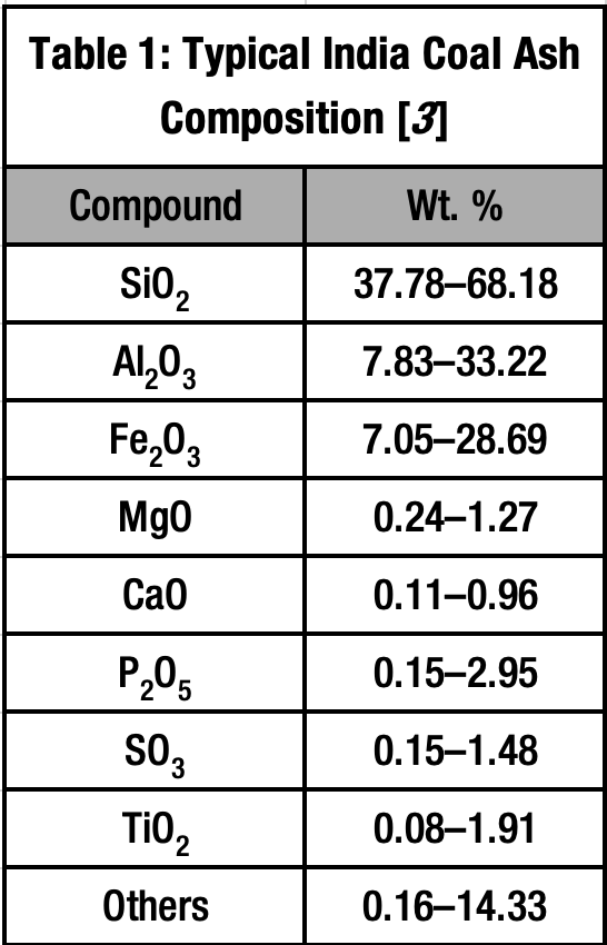
Therefore, high ash content from 20–50 wt% and high fusion temperatures are the two major challenges for gasification of Indian coal.
Overview of the gasification process
Figure 1 represents a process block flow diagram for a commercial dry-feed gasification technology with bottom quench design option.
Crushed coal with a specified top size is received from the coal yard at the coal milling and drying (CMD) battery limits. Coal is milled in a dry grinding mill with sufficient hot flue or inert gas for drying to produce fine pulverized coal with the desired particle-size distribution and target moisture content. In the coal pressurization and feeding system, coal passes through a series of lock hoppers under pressure. During the final stage, high-pressure carrier gas transports pulverized coal to the gasifier through opposing pairs of coal burners. High-pressure oxygen with a small amount of steam is also introduced to the gasifier through the coal burners. The coal and oxidant streams flow through multiple burners configured to form a radial flow inside the gasifier, where they react to form syngas and a mixture of molten ash and minute amounts of unconverted carbon.
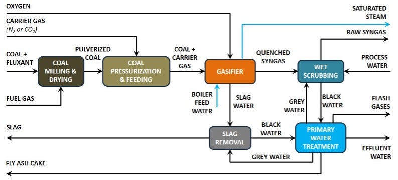
FIGURE 1. Gasification process block flow diagram from Air Products
The hot syngas and molten slag then enter the slag bath through a dip leg, which is protected by a continuous water layer formed by a quench ring and coarse spray nozzles. Within the slag bath, the syngas is rapidly quenched and becomes saturated with water vapor. The quenched syngas then takes annular space between dip leg and draft tube and exits the gasifier to the scrubbing section. The fused solids from the slag bath are then routed to a slag removal section which operates in batch mode to safely discharge the slag to an offsite location. The water with slag fines is routed to a primary water treatment section for solids separation.
The quenched syngas is transferred to a wet scrubber through a venturi scrubber to separate the entrained fine solid particles. A defined bleed stream of scrubber water is sent to primary water treatment. The primary water treatment system includes flash/heat recovery vessels and separators to recover heat and remove dissolved sour gas components.
Black water from the slag removal section and flash vessel bottoms are processed in a clarifier to further concentrate solids and collect water for internal reuse. The fine solids are discharged offsite as a dewatered filter cake, a solids-rich cake coming from settling/decanter. To prevent buildup of trace components within the gasification section, a bleed stream is taken out and routed to an effluent water treatment section outside the battery limits.
High ash content
The presence of high ash content in coal during gasification results in reduced syngas generation per a unit quantity of coal feed with a lower yield of hydrogen and carbon monoxide in the product stream. Hence, it is preferred to opt for a coal ash reduction step whenever feasible. If it is not a viable option, then the solids handling system should be designed within the battery limits to cater to the higher ash coal through appropriate equipment sizing. Typically, no additional or new equipment is needed to accommodate high ash while generating the same target syngas production.
High fusion temperature
The gasification process described in this article is a slagging-mode gasification process, meaning the gasifier operating temperature should be higher than the coal-ash fusion temperature to ensure that all of the ash present in the coal particle melts and flows down the reactor.
For higher fusion-temperature coal types, slag-modifying agents generally known as fluxant are blended with coal to reduce the fusion temperature. These are generally high-alkali metal oxides containing calcium originating from limestone.
To ensure optimized operation, the fluxant dosage rate should be accurately estimated to achieve the desired slag flow characteristics within the gasifier reactor.
Potential slag blockage
In the gasification process, swirling opposed burners create a stable flow field, promoting a uniform temperature profile and minimizing local cold spots at the slag tap. This reduces the risk of localized freezing and potential blockage of the slag tap and supports high carbon conversion across a range of ash loadings.
When equipped with a uniform, circulatory flow pattern, the gasifier slag-tap design imposes no inherent limitations on sizing. This enables customized configuration for high-ash coal applications, ensuring continuous and reliable slag discharge without risk of blockage, even under elevated ash loading conditions.
Black-water solids load
A swirl-driven wall attachment carries molten ash to the membrane wall where it forms a protective slag layer, so most of the ash exits as coarse slag rather than micron-scale carryover. In addition, the slagging efficiency (ratio of coarse slag formation to total ash) is higher at over 80% due to the specific reactor and feed system design. The result is a lower fines yield in the black-water loop and reduced erosion/maintenance in the black water system. Again, the engineering design of the black-water circulations system is carefully designed to maintain an optimum solids concentration to ensure smoother and more reliable operation of the system.
The membrane wall operates with a self-healing slag layer, enabling long service life under high solids loading.
Why downstream products matter
For chemical products such as ammonia, methanol, dimethyl ether (DME), urea and ammonium nitrate, processes typically require:
- Ultra-clean syngas (very low tar/organics and manageable contaminants)
- High carbon conversion (small percentage losses translate to large annual value loss at mega-scale)
- Stable H2/CO ratio and low methane for synthesis efficiency
- Large single-train capacity and high availability (>8,000 h/year)
- Lower unit count/plot space and simplified operation
These requirements strongly favor proven entrained-flow slagging technology for world-scale chemicals, while “ash tolerance” alone is not a sufficient selection criterion.
Case study: Performance comparison — Low-ash versus high-ash Indian coal
To illustrate the difference between low- and high-ash coal gasification performance, the following case study was performed. Each process section within the gasification process block diagram was analyzed to provide insights on design features to mitigate challenges associated with high-ash coal gasification.
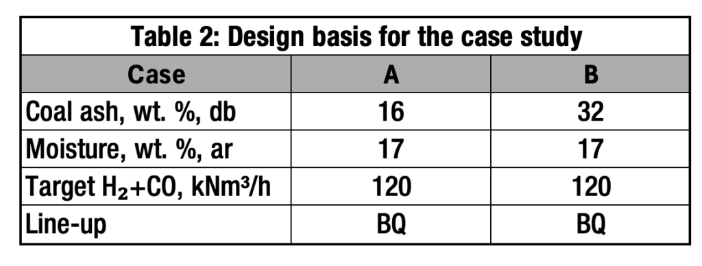
Key assumptions considered for this case study are shows in Tables 2 and 3.
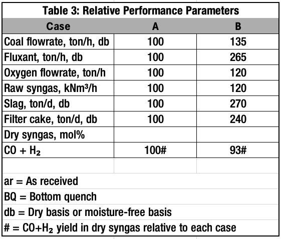
Coal milling and drying. The major equipment in this section includes a coal-grinding mill and fluegas or inert gas generator for drying. Coal and fluxant inlet flowrates are the design basis for this section. As can be observed in Table 3, the coal and fluxant flowrates for Case B are ~33% and 164% higher than Case A values, respectively. Therefore, the CMD section for Case B requires a higher-capacity coal mill and bigger fluegas generator to meet the desired grinding and drying requirements.
Coal pressurizing and feeding. Again, the design basis for this section is coal and fluxant flowrates. As Case B feedstock flowrates are higher, the coal lock hoppers should be designed with larger dimensions to maintain the same retention time. The carrier gas flowrate also increases in the same proportion.
The volumes of the sluicing vessels and critical valves sizing shall be carefully estimated by a design engineer to ensure smoother functioning of the coal processing and feeding section.
Gasification. Although there is no major change in the gasifier reactor section, the feedstock capacity may change the size of the coal feed line and burner channels. The bottom quench section will be designed with larger solids loading capacity to accommodate higher slag generation in Case B due to high ash coal. This section includes a dip leg, draft tube and slag bath.
Slag removal. The slag removal section consists of a slag crusher, slag sluicing vessel, drag chain, slag dewatering silo and associated circulating pumps, which shall be designed for higher solids capacity of Case B. Retention time and slag sluicing valve sizing are critical aspects that the design engineer pays additional attention to so that reliable operation of the slag removal section is ensured. Proportionate to the higher solids capacity, the size of the sluicing vessel will be larger in Case B.
Wet scrubbing. The raw syngas at the battery limit for Case B is higher than Case A. As the yield of H2+CO in the syngas for Case B is lower, the total raw syngas for Case B is higher to maintain equal H2+CO target generation among both cases. Therefore, the sizing of the wet scrubber, quench circulating water to the quench ring, the venturi scrubber and scrubber pump will be proportionately higher in Case B than Case A.
Primary water treatment. The bleed water from the scrubber bottoms and slag removal section and associated fines are higher in Case B than Case A. This will result in slightly larger flash vessels, condensate separators and deaerators. The capacity of heat exchangers and pumps also increases proportionately.
With excess filter-cake generation in Case B, the clarifier, grey water tank and filtration system will be relatively larger to accommodate the additional solids burden. The associated dosing chemicals and utilities will also increase accordingly. ♦
Edited by Mary Page Bailey
Acknowledgment
All images provided by authors
References
- PIB Delhi, Coal Gasification Key to India’s Energy Security and Industrial Growth: Union Minister G.Kishan Reddy, March 2026.
- PIB Delhi, Cabinet approves proposal to promote coal/rear coal gas generation with an outlay of Rs.37,500 crore, May 2026.
- Khare, P., Sharma, A. and Salkia, A., The chemical composition of tertiary Indian coal ash and its combustion behaviour – a statistical approach: Part 2, Journal of Earth System Science, Vol. 123, August 2014, pp. 1,439–1,449.
Authors
 Hidayathullah Mohammad (Email: MOHAMMH1@airproducts.com) is a gasification technology expert within Air Products’ Equipment Sales & Plant Support and Gasification Licensing organization. He is a member of the global team responsible for supporting Air Products’ gasification technology portfolio, including solid, residue, and partial oxidation gasification processes. With more than 19 years of experience in gasification and related technologies, Mohammed has expertise in process design, technology evaluation, project execution support and technology licensing. He holds a master’s degree in chemical engineering from the Indian Institute of Technology Madras in India.
 Nishant Singh (Email: SINGHN5@airproducts.com) is a business development manager for the India and CIS regions at Air Products within the Gasification Licensing organization. He has more than 15 years of experience spanning engineering, project execution, and business development across the industrial gas and energy sectors. He holds a Master of Science degree in Mechanical Engineering from Michigan Technological University.