Dry-coal-feed systems (DCFS) deliver pulverized coal to a gasifier. A study of the feed system with a lockhopper revealed findings that are contrary to conventional design approaches, including that increasing the number of lockhoppers offers operational and cost advantages
Several coal-based gasification technologies employ dry coal, rather than slurry, as feed. In all such processes, equipment is required to receive pulverized coal from the pulverizer at near-atmospheric pressure, increase its pressure, and continuously deliver it to the gasifier. The conventional design approach utilizes a three-vessel stacked arrangement, referred to in this article as the dry coal feed system (DCFS).
As part of an engineering evaluation, the feed system for a dry coal-fed gasifier operating at 1,000 psig was analyzed for a 3,000 short-tons-per-day facility. The study revealed key findings that were both unexpected and contrary to conventional design approaches. The information presented in this paper is based on an original study conducted in 2014, with costs updated to 2025 using best-effort estimates. These adjustments do not materially affect the conclusions of the original work.
Current design trends favor systems with capacities on the order of 3,000 short tons per day operating at approximately 1,000 psig. A conceptual representation of the DCFS for a gasifier operating at 1000 psig is shown in Figure 1.
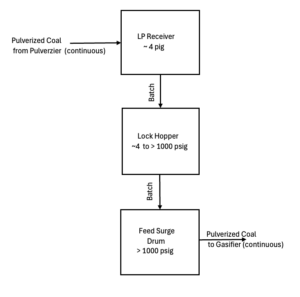
FIGURE 1. The schematic diagram shows the arrangement of a dry coal feed system (DCFS)
DCFS system description
The DCFS is typically a tall structure, often exceeding 150 ft in height. It includes a vessel known as the low-pressure receiver (LPR), located on the uppermost platform and operating at approximately 2 to 4 psig. A second vessel at ground level is known as the feed surge drum (FDSD), which operates at a pressure higher than that of the gasifier. There is also an intermediate vessel, the lockhopper (LH), positioned between the two. The LH cycles between the pressures of the LPR and the FDSD.
Moisture-conditioned pulverized coal, with a top particle size of about 200 microns (1 mm = 1000 microns), is continuously conveyed pneumatically to the LPR. From there, the coal is transferred by gravity in batches to the LH. After pressurization, it is discharged by gravity in batches from the LH to the FDSD. The LH is then let down in pressure to receive a new batch from the LPR.
With the LH initially isolated from both the LPR and FDSD and at low pressure, a time-based sequence is initiated consisting of the following steps (with typical durations representative of large-scale operation):
- Open inlet valve to the LPR and receive a batch of coal (6–8 minutes)
- Isolate from the LPR
- Pressurize with N₂ (or CO₂) to match FDSD pressure (6–9 minutes)
- Open discharge valve and transfer the batch to the FDSD (6–8 minutes)
- Isolate from the FDSD and let down pressure to LPR pressure (12–15 minutes)
- Repeat the cycle
As discussed in Ref. 1, cycle time represents a trade-off between equipment size and valve wear. Longer cycle times require larger vessels and valves, resulting in a taller structure, but reduce wear on the valves, which are both critical and costly components. For reference, a one-hour cycle corresponds to 8,760 cycles per year, with each cycle involving one opening and one closing. For large-scale systems, cycle times in the range of 30–40 minutes are generally considered optimal.
Full-port (FP), Class V or VI tight shut-off (TSO) metallic ball valves designed for solids service are typically used in this application. These valves are very expensive. Budgetary quotations obtained from a major U.S. supplier at the time of the study, and escalated to 2025 dollars, indicate costs ranging from approximately $33,000 for a 2-in. valve to about $450,000 for a 20-in. valve (including actuator), based on 900# flanged carbon steel (CS), Class V TSO, full-port valves with chromium-molybdenum (Cr-Mo) balls (Figure 2).
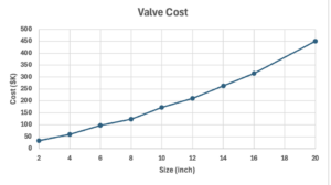
FIGURE 2. This graph shows valve cost according to size
Gas vented from the LPR is routed to a bag filter to recover entrained solids. Similarly, gas released from the LH during Step 5 is typically directed to the same bag filter. Design options for the LH vent system are discussed in detail in Ref. 1.
The continuous discharge of coal from the FDSD to the gasifier results in a gradual pressure decrease, which is compensated by the addition of gas. During the LH filling step, the FDSD is opened to the LH, allowing gas displaced by incoming solids to flow back into the LH. Occasional venting of gas from the FDSD is also required, due to factors such as changes in ambient temperature. This vent flow is relatively small and is regulated by a control valve located downstream of a sintered metal filter, which serves to capture any entrained dust.
Basis of study
The following represent the conditions of the study.
- Single-train gasifier with 3,000 short tons per day capacity
- Gasifier pressure of 1,000 psig
- N2 for LH pressurization (alternate of CO2 was also assessed and will be briefly discussed)
- Carbon-steel (CS) vessel when using N2, Cr-Mo for LH and FDSD when using CO2
- 900 # Class V TSO FP Cr-Mo ball valves with CS flanges with N2, or Cr-Mo flanges with CO2
- Escalated cost of $4.50 per lb. fabricated cost for CS vessels, $12 for Cr-Mo (budget quotes from fabricators)
- Escalated cost of $32 per ft3 of volume for steel-framed structure (from installed cost of other projects with comparable scope, dimensions and weight on structure)
Study results
Several configurations were evaluated. Case 1, designated as the Base Case, consists of one LPR, two LHs and one FDSD, all sized on the basis of a 30-min. LH holdup, cycling once per hour (this is known as a 1-2-1 configuration). Additional configurations examined included systems with 1, 3, 4 and 6 LHs — denoted as 1-1-1, 1-3-1, 1-4-1 and 1-6-1, respectively — with LH holdup and cycle time optimized for each case (Table 1). Conventional practice typically limits each LH to about 1,500 tons per day, consistent with the Base Case.
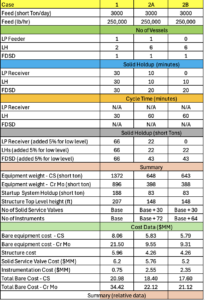
TABLE 1. Different lockhopper arrangement scenarios
The analysis shows that, at the elevated pressures considered, the 1-6-1 configuration is more advantageous. In this arrangement, each LH is sized for 10 minutes of holdup and cycles once per hour. The sizing basis and relative cost estimates for selected cases are summarized in Table 1. Case 1 represents the Base Case; Case 2A corresponds to the 1-6-1 configuration; and Case 2B represents a 0-6-1 configuration, similar to Case 2A, but without the LPR, while retaining the bag filter (discussed later). The 1-3-1 and 1-4-1 configurations yielded results very close to the 1-2-1 case and, given the accuracy of the cost estimates, were considered equivalent and therefore not presented. The 1-1-1 configuration resulted in significantly higher costs than the 1-2-1 case and is also omitted.
Wall thickness of vessels increases with both internal diameter and the operating pressure, and when over 2-in. thick is typically made of at least two plates of thinner layers. There is a large drop in the number of fabricators worldwide that can supply large-size vessels with over 2-in.-thick walls.
On paper, for a given holdup, it is feasible to limit the wall thickness by selecting smaller-diameter vessels with larger aspect ratios but as the aspect ratio for the vessel goes up, so does the height of the structure, and therefore the total system cost. That is, the structure plus the added length of piping, instrument cables and instrument trays. One should also note that using a very-high-aspect-ratio vessel with pulverized coal, which is irregularly shaped, can lead to operational issues even with the best feasible designs due to coal particles bridging.
Comparing Case 2 to Case 1 leads to the following observations:
Benefits
- Reduced total pressure vessel metal weight (reduced cost)
- Reduced structure height, so combined with reduced weight, reduced holdup and less piping and wiring, leading to cost saving
- More valves, but of smaller ball diameters. As shown previously, there is a significant increase in cost of FP, TSO solids-service ball valves for solid and gas service with size, so the total cost actually went down
- More independent inlet/outlets for feed to flow through, so production loss impact will likely be less in the event of failure in one path
- More fabrication shops worldwide capable of building the vessels
- Reduced total holdup for the system as a whole and each vessel within it (so less weight for operation to have to manage in case of flow stoppage)
Drawbacks
- More instruments used for measurement, hence higher instrument cost
- More equipment and instruments to maintain and track documentation for, so some added maintenance and warehousing cost
FDSD operation
Level fluctuations in the FDSD require addition or venting of gas to hold near-constant pressure in the vessel. As previously noted, the FDSD is opened back to the LH during fill step, so displaced gas can vent back to the LH. In theory, this should allow pressure in the FDSD to remain constant as it is being filled. In practice, the FDSD does experience a momentary pressure surge which takes time to dissipate. Therefore, higher fluctuations in level suggest higher degree of difficulty in keeping the pressure constant and in good control (Figure 3A). Achieving good pressure control in the FDSD with little or no fluctuations is important to stability in gasifier operation because it eliminates pressure surging in the injectors.
Magnitude of level fluctuations in the FDSD decreases as the number of LHs is increased. The figure below shows how level in the FDSD fluctuates using a system with 30 minutes of surge in the FDSD and two LHs, each with 30 minutes holdup, cycling once per hour:
In comparison, the same system is shown below when six LHs each with 10 minutes holdup, cycling once per hour, plotted on the same Y-axis scale as the previous example. A significant reduction in level fluctuation is observed (Figure 3B).
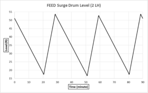
FIGURE 3A. With two lockhoppers the level in the surge drum fluctuates widely
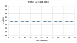
FIGURE 3B. With six lockhoppers, the level in the surge drum remains relatively stable over time
Use of CO2 instead of N2
Some of the N2 used in the DCFS will end up in the gasifier becoming a diluent in the synthesis-gas product. Using CO2, a product of gasifier operation, will help remedy this. The issue with CO2 is that it will self-refrigerate in the LH as the pressure is let down, but this is manageable by proper design providing higher heating levels in the mill, using Cr-Mo material, and heat tracing the LHs and FDSD. Use of higher cost Cr-Mo makes the cost advantage of Case 2 even more significant.
The CO₂ Mollier diagram shown in Figure 4 illustrates how liquefaction can be avoided through appropriate preheating from the pulverizer and by controlling the rate of pressure letdown.
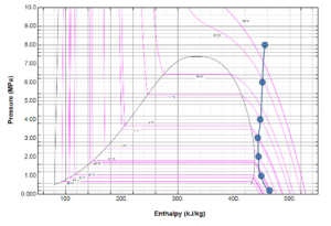
FIGURE 4. The CO2 Mollier diagram shows how liquefaction can be avoided
Need for LPR (Case 2B)
The LPR acts as a surge vessel for the LHs. With six LHs, the likelihood of two or more failing simultaneously is extremely low, making the benefit provided by the LPR questionable. An alternative concept can be envisioned in which material is transferred directly from the mill into the LHs, using valving to direct flow sequentially from one LH to the next, as presented in Case 2B. This configuration still requires the bag filter; and, assuming there is insufficient space one level below for its installation, this approach has only a minor impact on the overall height of the structure. It does, nevertheless, eliminate one piece of equipment, along with its associated piping and instrumentation, while also reducing the structural load on the upper level, and requiring a significantly smaller top-level platform area.
For a 3,000 short-tons-per-day dry-coal-feed system operating at very high pressures, employing six lock hoppers instead of the conventional system (two 1,500-short-tons-per-day units) is expected to provide significant operational and cost advantages.
Edited by Scott Jenkins
References
- Jazayeri, B., Engineering Fluidized Beds Peripheral Systems, in “Engineering Fluidized Beds Peripheral Systems,” Jazayeri, B., Ed., Chapter 1, pp. 4–48, Amazon KDP, 2026.
Author
 Behzad Jazayeri is an experienced process engineer collaborating with many leading EPC companies across the U.S. He has served as an embedded owner’s engineer on multiple projects, providing technical leadership and bridging design and execution. Jazayeri is a subject matter expert in the design and scale-up of reactors and gas–solid systems, particularly fluidized bed operations spanning pilot to full commercial scale. Over the course of his career, he has led the process design of numerous units, including nine pilot/demo plants and seven first-of-a-kind commercial systems ranging in size from 7 cm to over 12 meters in diameter. Jazayeri has designed over 30 fluidized-bed reactors that are currently operating worldwide. He is the author of eleven technical publications and two technical books, and a co-inventor of one patented technology.