Presented here are practical considerations concerning the equipment and methods used for experimental verifications of simulations
The use of process simulation tools for modeling distillation columns is invaluable for designing plant-scale columns. However, it can be difficult to know if the simulator is generating accurate predictions. Additionally, there are potential problems associated with distillation columns that process simulators do not address. Hence, experimental distillation studies are quite important to either verify the simulation results or to provide a path forward to improve the simulations (Figure 1). As a followup to a previous article that discussed the needs for experimental validation [1], this article presents the experimental methodologies used for validating process simulations.
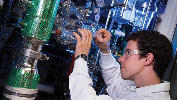
Figure 1. Experimental studies are important to either verify distillation simulations or to provide a path forward to improve the simulations
Batch, continuous or pilot?
Once the need for experimental validation of distillation simulations has been identified, a decision must be made as to whether the experiments should be conducted in a batch column, a stand-alone continuous column or a continuous column within a pilot plant representing all, or part, of the entire process. Below are some of the initial considerations for each of these options:
-Laboratory batch column
- Relatively simple and inexpensive to set up
- Will not represent the same composition profiles, temperature profiles or reboiler residence times as a continuous column
- Can validate some or all of the required vapor-liquid equilibrium (VLE) predictions from a simulator
- Can demonstrate, qualitatively, decomposition, byproduct generation, foaming and fouling issues
- Can help to decide if distillation is a viable option for the separation scheme
-Stand-alone continuous column
- More difficult and expensive to set up than a batch column, but less costly than a full separation train
- The same composition profiles, temperature profiles and reboiler residence times that will be experienced in the full-scale column can be experimentally modeled
- VLE predictions can be validated for full-scale composition profiles and liquid/vapor (L/V) ratios
- Can demonstrate, more quantitatively, decomposition, byproduct generation, foaming and fouling issues
-Continuous column in pilot plant with recycles
- All the same considerations as for the stand-alone column
- Byproducts may form in other parts of the process that build up and affect the column
- Products and byproducts from the column may affect other process equipment
Often, initial experiments are conducted in a batch column, and if warranted, followed by a continuous column. The size of the experimental column is another important issue. Sizing is discussed in the next sections.
Batch column considerations
If the VLE for a binary system is unknown, the ultimate path forward is to experimentally measure the VLE using an ebulliometer. However, the expense and effort of this method may not be warranted in many cases. If there is a reasonable degree of confidence in the physical property model for the distillation simulator and there is a desire to just check the model or tweak its parameters, experimental testing in a simple laboratory batch column may be acceptable. A batch column is relatively easy to set up and to operate. A significant amount of useful data can be collected from experiments with this equipment.
However, the use of a batch distillation simulation program that accounts for tray volumes and process changes with respect to time, may be necessary to use the laboratory batch-column data for physical property validation. Many engineers conducting process simulator work are simulating continuous processes and do not all have experience with batch distillation simulators. To properly evaluate experimental batch data, simulations must be run in a corresponding batch mode so that the experimental data can be compared to the corresponding simulator prediction. The effort required to develop and run the batch simulation needs to be taken into consideration.
For systems operating between about 5–10 mm Hg and atmospheric pressure, the traditional equipment used for batch validation purposes is a 25–50-mm dia. vacuum-jacketed column with Oldershaw-style trays (Figure 2). The kettle can be charged with an initial composition of the chemicals of interest, and brought to total reflux. After reaching steady state, the reflux ratio can be set at a finite value to remove a small distillate sample of the light-boiling compounds, and a sample of the kettle can be taken at the same time. Keep in mind that as distillate is removed, the reflux ratio is temporarily being lowered and the separation changed, so take as small of a sample as possible. Collecting samples at total reflux significantly reduces the concern about heat effects, since the L/V ratio will be essentially 1.0 throughout the column, no matter how much condensation occurs in the column.
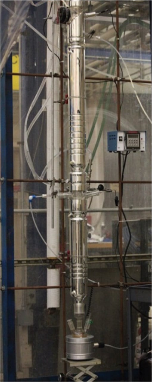
Figure 2. Shown here is a laboratory Oldershaw distillation column with a vacuum jacket
It is important to know the actual tray efficiency for the experimental column with the chemical system of interest whose physical property model is being validated. If necessary, the tray efficiency of the laboratory column can be measured using a known binary system that is as similar as possible to the actual chemical system. This experiment should be conducted at nearly the same flowrates and pressure that will be used for the batch-distillation experiment with the actual chemical system. Compare the predicted and actual tray efficiencies for the known binary system and adjust the efficiency prediction for the actual chemical system.
Make sure that the compositions at the top and bottom of the column are in a range that will allow accurate analyses. At very low concentrations of the heavy-boiling component at the top of the column or light-boiling component at the bottom, the analytical errors may represent several theoretical stages in the column.
The heat loss throughout the column should not be so great as to cause major changes in the tray activity (froth) between the top and the bottom of the column. The worst case is to have dry trays at the top of the column and nearly flooded at the bottom. Experimental setups with tall columns, high operating temperatures, and/or small diameter columns will be especially prone to troublesome heat-loss problems.
It is likely that some of the experiments will involve charging the kettle with the actual chemicals and removing the bulk of the kettle charge overhead as distillate cuts, possibly every 5–10% of the kettle charge. Data collected from such batch tests will provide an indication as to whether distillation is a viable option, help determine the difficulty of the separations, and generate samples that can be used for physical property validation.
One experimental approach with such batch testing is to set the reflux ratio at a value that is relatively high, but not so high as to prevent the experiment from being completed in a reasonable time. However, this method raises two additional concerns. Heat loss becomes important, since it can change the L/V ratio in the column and cause the effective reflux ratio throughout the column to be different than what would be expected based on the measured reflux ratio. Also, the column will never be at steady state, since the compositions within the column are continuously changing. The negative effects from the unsteady state problem can be reduced by increasing the kettle volume, relative to the column size, and increasing the reflux ratio. These changes will slow the rate of composition change in the column. A batch-distillation simulator will likely be required to correctly evaluate the data from such experiments.
Another experimental approach involves removing a series of distillate cuts at a finite reflux ratio and putting the column on total reflux after each cut. After the column reaches steady state at total reflux, a small distillate and kettle sample are removed at a high, but finite reflux ratio, then the column proceeds with the next cut (using a finite reflux ratio). This method is more time-consuming, but it solves the heat-loss and unsteady-state problems. It may be possible to simulate these data using a continuous distillation simulator.
Equipment considerations
Size Selection. For small-scale experimental continuous-distillation columns that are intended to model the operation of a full-scale column, significant judgement is required to choose the equipment size necessary to conduct useful validation experiments while minimizing costs. Generally, larger-scale columns will provide better data but the cost of the experimental effort will increase with size. Several concepts are discussed below that should help with the trade-off between the quality of the data and the cost of the effort.
Generally, to minimize the cost of the experimental work, it is desirable to use the minimum size that will allow meaningful scaleup data to be collected. For columns using Oldershaw-style trays, the minimum recommended diameter is 50 mm with a minimum tray spacing of 50 mm. For smaller columns, especially for chemical systems with high surface tension, the tray activity (froth on tray) becomes more erratic and difficult to quantify. In addition, smaller columns are more difficult to control. Even with the use of insulation and heat tapes (instead of vacuum jacketing with silvering), the higher surface-area-to-volume ratio of columns smaller than recommended makes it more difficult to run the column adiabatically. However, in certain cases, a smaller column may be adequate.
For columns using random packing instead of trays, the column diameter is recommended to be at least 5–15 times the packing diameter, depending on the packing. In the case of Pro-Pak 0.16-in. packing, the minimum recommended column diameter is 20 mm. For structured packings, columns with diameters as small as 20 mm may be used, as is the case with Sulzer EX gauze packing (designed specifically for laboratory columns).
Other sizing considerations include the following:
- If the distillation column is part of a pilot plant that includes other process equipment, such as a reactor, there may be a minimum size for this other equipment. Material balance calculations will then dictate the distillation column size
- If a reactor, distillation column or other major equipment already exists, the desire to utilize the existing equipment may affect the choice of the size of the pilot unit and of the distillation column
- To ensure accurate data for all important flows and compositions, the considerations of managing the smallest critical stream may determine the size of the pilot unit and the distillation column
- If samples need to be generated, their volume requirements will be an important factor in the sizing decision
- The availability of feed materials or the cost of disposing of wastes may place an upper limit on the pilot plant size
Cost estimation. Cost is always a consideration in the sizing of an experimental unit. Although costing is beyond the scope of this article, Ref. 2 provides good insights into the cost issues involved with designing and constructing a pilot plant.
Materials of construction and equipment design. If the column pressure is 1 atm or less, glass should be considered as the material of construction for the column. Glass allows visual observation of internal flows, foaming, and fouling issues (Figure 3). Visual observations are not only important for collecting reliable data for model validation, but will be invaluable for plant equipment design considerations.
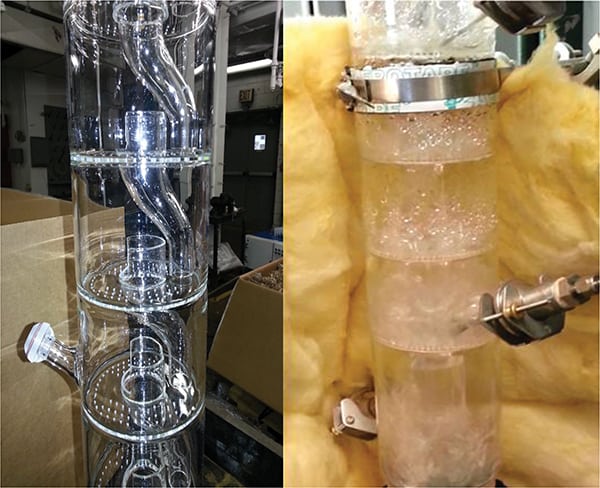
Figure 3. These photos show unjacketed Oldershaw-style column sections with (right) and without (left) liquid and vapor traffic. These column sections were custom-made with a reduced number of holes for high L/V ratios and with side ports for a thermocouple or sample apparatus. Glass allows visual observation of the tray activity (froth, foaming and fouling issues)
If trays are to be modeled, an Oldershaw-style tray is recommended for the contactor. The standard Oldershaw design works well for many chemical systems. However, for processes with extreme L/V ratios, high surface tensions, high viscosities, or residence-time concerns, several manufacturers have the capability to create custom trays. If the column will use packing, then open tubes can be utilized for the column sections, with a screen at the bottom to support the packing. At the feed point and between packed sections, there should be a collector-distributor section that collects all the liquid from the bottom of the packed section above and redistributes it properly to the next packed section below. Usually, a tube-style distributor is adequate (for 50–75-mm dia. or less, with one tube that introduces liquid to the center of the packing). There will be a recommended maximum packing height for each packed section that can be provided by the packing vendor. Reflux to the top of the column can be accomplished with either a liquid-dividing head, or a system of flowmeters and pumps that measure and control the reflux and distillate. The liquid-dividing head uses a timer mechanism to alternately divert the entire condensate flow as either column reflux or distillate product. The liquid-dividing head has the advantage of simplicity, but does not allow for direct measurement of the flows, and the splitter device can become stuck if the electromagnet is misplaced or there are fouling issues. For packed columns, the reflux must be distributed properly to the top packed section.
If custom trayed column sections are to be purchased, it is strongly recommended that a port be incorporated into the column at every two to three trays, which could be used for a thermocouple or a liquid sample extraction point (it may be possible to install both in the same port). This arrangement will allow the temperature and liquid composition profiles to be determined directly and will be invaluable for any system with uncertainty regarding the physical properties or the generation of byproducts. For packed columns, these ports could still be useful, especially for thermocouples. It may be difficult to obtain a liquid sample from the packing, but it may be possible to collect vapor samples with the proper sampling arrangement.
The choice of the reboiler residence time should be given ample consideration, since this time can affect the amount of degradation and byproduct formation that occurs in the base of the column. Also, the reboiler configuration and heat source should be designed to avoid excessive skin or localized temperatures.
Insulation. Knowing the liquid and vapor flowrates is critical for a distillation column that is producing simulator validation data. Since heat loss will affect these flows, how the column is insulated is an important issue to consider. If the column is glass, the two main options are vacuum-jacketing or insulation with heat tape. Vacuum jackets traditionally have the interior surface silvered to reflect radiant heat, and there is usually a non-silvered vertical “line” (about 6 mm wide) the full length of the column section on the front and back that allows viewing into the column. For relatively short distillation columns that are not very hot, vacuum-jacketing is acceptable. However, although this is a simple and elegant means of insulating the column, there will be some heat loss and additional internal reflux. The other alternative, insulation with heat tape, allows a column to run at near adiabatic conditions no matter the operating temperature (Figure 4). It can be used on glass and metal columns, and has the advantage of reducing the cost of the column sections, since the expense of the vacuum jacket is avoided. This method is somewhat more cumbersome, in that it requires wrapping each column section with insulation and heat tape. This inconvenience is offset by the increased confidence that it provides better experimental data. The traditional way to implement this method of insulation is to wrap the column with two layers of insulation, with heating tape wrapped between the layers. One thermocouple is placed next to the column with another one near the heating tape (on the column side). The input for the controller is the temperature difference, with a setpoint of zero degrees. This represents no heat loss or gain. Several sections of heat tape and insulation should be installed based on the expected temperature profile for the column. This will minimize the range of column temperatures for each heat tape and insulation section, so that each section can be as close to adiabatic conditions as possible.
Air leaks. Air leaks into vacuum columns, especially those operating under high vacuum, can obviously affect the vapor flowrates, if severe enough. However, at leak rates well below this threshold, the leaked oxygen may contribute to byproduct formation, particularly if the air is entering the reboiler. In addition, the flowrate of the leak will be additive with any nitrogen blowback for pressure and differential-pressure sensors, and will contribute to light-boiling component losses from the condenser to the vent system. The loss of lights in this manner can introduce significant errors if not properly considered.
Concerns and recommendations
The relative liquid-to-vapor flowrates (L/V ratios) and tray or packing efficiencies must be understood to use the experimental data to validate the physical property models used in the simulator. The following discussion provides some guidance to assist with that task.
New distillation columns should be checked to ensure that all sensors are reading correctly and that heat losses are controlled or, at least, understood. The efficiency of the trays or packing should be determined at operating conditions near the design conditions. Ideally, these tests should be conducted using a binary chemical system, with known VLE, that is as close to the actual system as possible, just as for the calibration of a batch column. This method eliminates the uncertainty due to incorrect VLE predictions, leaving the relative vapor and liquid flowrates and the contactor efficiency as the unknown parameters to be determined initially.
If there is a concern about whether the liquid and vapor flowrates are accurately known in the experimental apparatus (that is, heat losses are not minimal or not well understood), use the following procedure. Simulate the column at a pinched condition (for instance, reflux-to-distilate ratio = R/D= 0.5) and vary the Murphree Efficiency between 40 and 80% to ensure that the predicted distillate and bottoms compositions are relatively insensitive to tray efficiency. It may be necessary to change the feed composition or to adjust the R/D ratio in the simulation to ensure that the separation is not sensitive to the Murphree Efficiency. Make sure that accurate analyses are possible at the predicted distillate and bottoms compositions. Then run the experiment at those conditions in the actual column. Since the VLE curve is known, if the distillate and bottoms compositions from the experiment do not agree with the computer simulation, these differences are an indication that the internal flows are different than those used in the simulation. The differences could be due to inaccuracies in the flow sensors, or heat losses from the column causing internal reflux.
After any problems are corrected from the previous test, the column should be evaluated with respect to efficiency. The column should be operated at conditions as similar as possible to the design conditions for the actual system. Keep in mind that the efficiency of a vapor-liquid contactor is affected not only by the L/V ratios, the pressure, and the composition, but also by the absolute flowrates. The amount of bubble/froth activity on a tray will affect the interaction between the phases, and, therefore, the efficiency.
For packing, liquid flowrates will affect the film thickness, liquid residence time, and surface turbulence; vapor flowrates will affect the degree of vapor mixing, vapor residence time and surface turbulence of the liquid, all of which will affect the packing efficiency or HETP (height equivalent to a theoretical plate). Ideally, the efficiency will be estimated using a software tool, or equations from the references provided earlier [ 1], and the calculations compared with the actual efficiency. This comparison will calibrate the efficiency predictor tool. If sample points are available in the column, the actual column profile can be compared with the computer simulator predictions to show if deviations are consistent throughout the column or tend to vary at one end of the column relative to the other.
Finally, the column can be operated with the actual chemical mixture. The efficiency prediction tool can be used to estimate the contactor efficiency for the actual system, incorporating any tuning adjustment. Now, the relative and absolute internal liquid and vapor flowrates are known and a good estimate of the contactor efficiency is available. Any discrepancies between actual and predicted composition profiles (and temperature profile) can be attributed to errors in the distillation simulator’s physical property model, and the parameters for this can be adjusted as necessary.
Concluding remarks
Key points to consider when contemplating the need to experimentally validate distillation simulations include the following:
- Without experimental validation, it is difficult to know if the simulations are accurate.
- Byproduct generation, foaming and fouling are difficult or impossible to predict by process simulators.
- Experiments should be conducted to validate distillation simulations and to determine if other non-simulated problems will occur.
- The main concepts that affect the separation in a distillation column are the VLE, L/V ratios, and contactor efficiency (pressure also plays a role).
- Major experimental options include the scale and whether to use a batch column, a stand-alone continuous column, or a continuous column within a pilot plant.
- A laboratory batch column may be able to provide adequate initial data for validation purposes.
- If an experimental continuous distillation column is to be utilized, several factors must be considered regarding its size.
- Heat loss should be minimized or properly accounted for in any experimental column.
- Initial experiments should be conducted to ensure that L/V ratios can be set at desired values and that contactor efficiency can be predicted.
- After ensuring that the experimental apparatus functions properly and is well understood, experiments should be conducted with the actual chemical mixture.
References
1. Graham, G., Pednekar, P. and Bunning, D., Experimental Validation of Column Simulations, Chem. Eng., February 2018, pp. 30–37.
2. Nunley, R., Considerations for Estimating the Costs of Pilot Scale Facilities, Chem. Eng., December 2016. pp. 38–46.
3. Nunley, R., Managing Heat Loss in Pilot Plant Operations to Simulate Full Scale Operation, paper presented at the AIChE National Spring Meeting, San Antonio, TX, March 2017.
Authors
 Glenn Graham is a distillation SME and senior chemical engineer at MATRIC (Mid-Atlantic Technology, Research, & Innovation Center, P.O. Box 8396, South Charleston, WV 25303; Phone: 304-552-6554; Email: glenn.graham@matricresearch.com; Website: www.matricinnovates.com). Prior to his position at MATRIC, Graham worked for Union Carbide Corp. and The Dow Chemical Co. as a distillation specialist in their R&D separations groups. Graham holds a master’s degree in chemical engineering from Montana State University.
 Pratik Pednekar is a project manager and research chemical engineer at MATRIC (Email: pratik.pednekar@matricinnovates.com). He works in the areas of process conceptualization and development, laboratory experimentation, pilot plant testing and technology evaluation. Prior to working at MATRIC, Pednekar was awarded his Ph.D. from West Virginia University in the field of process development, involving simulation, optimization and reactor modeling.
 Don Bunning is currently employed by MATRIC (Phone: 304-720-1049, Email: don.bunning@matricresearch.com). He has extensive experience in process development, reaction engineering, new catalyst development, demonstration of new technologies in pilot units, commercialization, on-site startup support, and licensing of the technologies. His more than 45 years of R&D experience in the chemical industry includes technical and management positions at Union Carbide and Dow Chemical. He hold an M.S.Ch.E. from the University of West Virginia and is a registered P.E. in West Virginia.