Control valves ensure safe and efficient operation of process plants by regulating the fluid flow in connected pipes. This one-page reference outlines key considerations for specifying control valves during the design phase of a plant.
Valve sizing. The size of a control valve is derived from its flow coefficient (Cv), a parameter defined as volumetric flowrate (in gal/min) of water through the valve at 60°F when pressure drop across the valve is 1 psi. Cv is calculated using the formula given in the standard ISA-75.01.01-2007 (Flow Equations for Sizing Control Valves).
Valve controllability. Valve controllability should be effective over the entire range between minimum and maximum flowrates. This can be established by estimating the maximum and minimum Cv that correspond to maximum flowrate and minimum flowrate, respectively. In general, the controllability of a control valve is deemed acceptable if its travel at maximum flowrate does not exceed 90% of the rated travel, and if travel at minimum flowrate is in the range of 10–20% of the rated travel. This means the ratio of estimated maximum Cv to estimated minimum Cv should preferably not be more than 15. If the ratio far exceeds this value, travel at minimum flow may be less than 10% of the rated travel, or the travel at maximum flow may be greater than 90% of the rated travel — both scenarios mean poor controllability of the valve.
Cavitation. When fluid is flowing through a control valve, the minimum pressure occurs at the vena contracta (the point in a fluid stream just downstream of a valve opening where the cross-sectional area of the jet is at its minimum, the velocity is at its maximum and the static pressure is at its lowest), then pressure increases along the path of flow until the fluid reaches the outlet of the control valve.
For liquids, if the pressure at the vena contracta is less than the vapor pressure of the liquid, vapor bubbles will form (Figure 1). Downstream of the vena contracta, pressure recovery takes place, resulting in higher pressure at the valve outlet than at the vena contracta. If pressure at the outlet of the control valve exceeds the vapor pressure, the vapor condenses and bubbles collapse. As bubbles collapse, it causes impact on the valve body and creates noise. This phenomenon is called cavitation. Full cavitation occurs when pressure drop across the control valve is more than or equal to a certain minimum pressure drop (or critical pressure drop), and the pressure at the outlet of the control valve is more than the vapor pressure of the liquid.
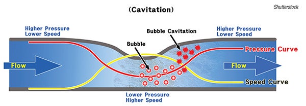
FIGURE 1. When the pressure in the fluid stream is less than the vapor pressure, bubbles can form and cavitation can occur
Multiple operating cases. Whereas a control valve is generally specified for three cases — minimum, normal and maximum flowrates, with corresponding pressure drops — there may be more than three operating cases. In such situations, normal flowrate and corresponding pressure drop should be specified in accordance with the normal operating case, whereas other operating cases (if there are more than two) should be narrowed down to two cases.
When narrowing down the operating cases, Cv should be estimated for each case. Then, minimum and maximum flowrates (and corresponding pressure drops) should be specified in such a way that they correspond to the minimum and maximum Cv of the control valve, and the Cv corresponding to all other cases should lie between minimum and maximum Cv.
Valve type. Compact and with generally low cost, butterfly valves are often the first choice. However, constraints may dictate otherwise. For instance, if high pressure drop across the valve is required, a globe valve may be better. Because the resistance of a globe valve is higher than that of a butterfly, higher pressure drop can be obtained across a globe valve with reasonable size. In liquid applications, high pressure drop could lead to cavitation. As the pressure-recovery factor of globe valves tends to be higher than that of other valve styles, cavitation can often be avoided with globe valves.
Leakage class. The allowable control valve seat leakage is specified in terms of ANSI/FCI 70-02-2006 leakage class. This standard recognizes six classes of allowable seat leakage (Class I, II, III, IV, V and VI). Class I means the highest allowable leakage; Class VI is the least allowable leakage. Generally, control valves for chemical process industries (CPI) applications are specified with leakage Class IV. However, in situations where tight shutoff is required, at least Class V should be specified. If a valve discharges to a flare, or is controlling fuel flow to a burner, it should be Class VI.
Flow. Here are common types of inherent flow characteristics:
• Linear — Valves with an ideal linear inherent flow characteristic produce flowrates that are directly proportional to the amount of valve plug travel, throughout the travel range.
• Equal percentage — Ideally, for equal increments of valve plug travel, the change in flowrate may be expressed as a constant percentage of the flowrate at the time of the change.
• Quick opening — A valve with quick-opening flow.
Editor’s note: Material in this column was adapted from the following article: Singh, S.K., Key Considerations in Specifying Control Valves, Chem. Eng., March 2017, p. 84–87.