Determining the field performance of centrifugal compressors can benefit operation and maintenance of the equipment. Presented here is an overview of the parameters that must be measured and calculated for effective testing
Compressors are used in all areas of production and in many different sectors of the chemical process industries (CPI). Production facilities can have a number of compressors of different types and in a range of sizes. The three main compressor types are centrifugal, axial and reciprocating. This article focuses on centrifugal compressors (Figure 1) and how field performance testing can be carried out in this equipment class to benefit the end-users, manufacturers and maintenance personnel. The benefits of field testing for existing units include the ability to quantify performance deterioration as a function of equipment age, to determine if and when certain maintenance tasks should be performed, and to identify specific equipment components for product improvement. For new units, field testing helps validate product performance.
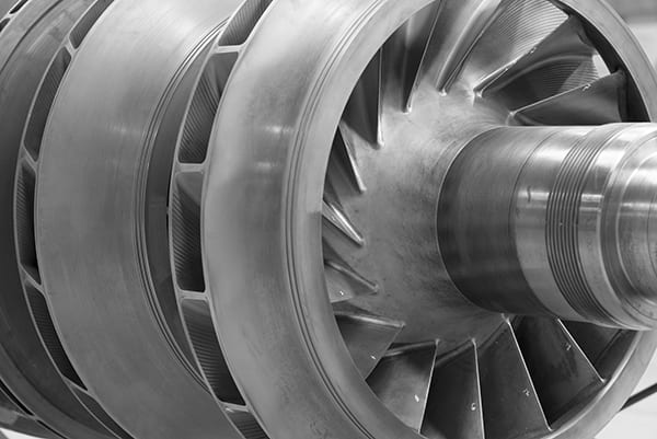
Figure 1. Performance tests on a multi-stage centrifugal compressor, like the one shown here, will quantify the factors of energy, head, work and flow
Performance principles
Regardless of compressor type, there are certain terms and parameters that will be used to define and quantify equipment performance. Primary among these are energy, head, work and flow. Energy is a parameter of the fluid in question, and will most commonly be defined as the total enthalpy of the fluid. Enthalpy is a combination of the kinetic (fluid velocity) and potential (static pressure) energy of the fluid. Because enthalpy is a derived term, there is no direct way to measure the enthalpy of a fluid. Instead, it is common practice to rely on equations of state (EOS) that relate measurable parameters (most commonly temperature and pressure) to derived terms, such as enthalpy and entropy, for a given fluid composition. A variety of EOS are available, and each will be best applicable for only a given set of fluid compositions over a specific range of operating conditions. Because of this, it is important that all parties involved in a performance test understand and accept the chosen EOS.
Head is a measure of the increase of energy within a fluid, and is typically defined as the change in enthalpy of the fluid between the suction and discharge conditions. Work is the mechanical means of transferring energy into the fluid.
Flow can be defined in terms of mass or volume, with volume taking one of two common forms. The first is the capacity, or actual flow, which considers the volume flow for the actual pressure and temperature of the fluid, usually at inlet conditions. The second is referred to as standard, or normal, flow, and calculates the volume flow for the given mass flow at a “standard” condition. For example, this could be a temperature of 60°F and pressure equal to 14.7 psia. For either volume flow term, the mass flow would be identical.
Measurements and calculations
The data gathered to determine performance include temperatures, pressures, flow and gas composition. Temperatures and pressures are relatively straightforward to collect using a variety of available sensors. However, flow can be a bit more complex to determine. Such measurements often rely on additional measurements, but there are still a number of sensor options available. Gas composition is probably the least accessible data to obtain, either requiring an online gas chromatograph (rarely available in most installations), or sampling of the fluid for analysis by a laboratory after the testing.
In addition to these base measurements, some common performance parameters that will be generated include the work, head and efficiency. Work and head, discussed earlier, lead to the definition of efficiency, which can be defined in many different ways.
First, there is the thermodynamic efficiency that only involves the actual compression process, and relates the actual head to an ideal head. The ideal head can also be defined in multiple ways; the two most common are isentropic and polytropic. It is critical to understand which of these two definitions is being used in a given case. Isentropic efficiency calculations assume that the thermodynamic process is adiabatic, and compares the actual head to the ideal head, with entropy at the suction and discharge assumed to be the same.
Polytropic efficiency compares the actual head to the head conceptually calculated by breaking the entire compression step into a number of smaller steps, with some heat added at each step. The two processes converge at low pressure ratios, yielding identical results. One benefit of using polytropic efficiency is that for multistage machines, if all stages have the same polytropic efficiency, then the entire machine polytropic efficiency is equal to the stage polytropic efficiency. Overall machine isentropic efficiency in this case will be lower than the stage isentropic efficiency.
Another way that efficiency can be defined is the mechanical efficiency of the compressor. This usually involves additional measurements to evaluate the mechanical work going into the compressor, usually through the use of a torque-meter. This allows calculation of the compressor efficiency as the actual head compared to the mechanical work going into the compressor.
Finally, a total system efficiency can be generated if measurements are taken of the total energy being put into the system. For electric-motor-driven compressors, the total energy can be determined based on electrical measurements and knowledge of the motor. For engine- and gas-turbine-driven compressors, knowing the fuel composition and flowrate can be used to determine total energy input.
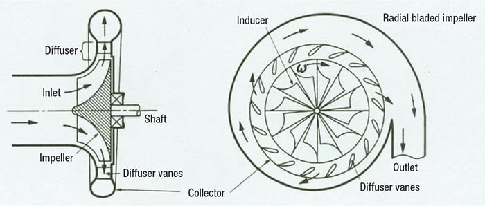
Figure 2. Centrifugal compressors have a rotating impeller that imparts head to a fluid
Centrifugal compressors
A centrifugal compressor uses the rotating energy of an impeller to impart head to a fluid primarily by first accelerating the fluid, and then converting the kinetic energy into potential energy by slowing the fluid. The typical internals of a centrifugal compressor are shown in Figure 2. Fluid enters the compressor and is directed in the inlet toward the rotating impeller. The blades on the impeller are designed to accelerate the fluid either axially or radially. There can be a potential energy rise due to the impeller blade geometry, but the majority of energy increase after exiting the impeller will be primarily kinetic. In order to convert this energy into a static pressure, the diffuser section will convert the kinetic energy into static energy by slowing down the fluid flow before it is directed to the outlet in the collector.
The design of each of these individual components can have a significant effect on the compressor performance, and therefore, must be considered carefully for each specific application. In addition, a centrifugal compressor can use multiple impellers in many different configurations to either increase the operating flow or compression ratio of the whole unit, with each individual impeller and diffuser sets of the compressor possibly comprising different designs.
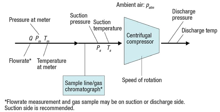
Figure 3. The diagram shows the locations of test instrumentation for a centrifugal compressor [4]
Field performance testing
One of the first things to consider when planning a performance test of a centrifugal compressor is the placement of sensors for gathering the operating conditions of the system. The ideal layout of measurements is shown in Figure 3. Included is a flow-measurement device (preferably on the suction side of the unit), instruments for measuring temperature and pressure on both the suction and discharge sides (although discharge temperature is not necessary), a means for determining gas composition, a means of measuring the unit rotational speed, and instruments to measure atmospheric conditions (mostly to correct gage-pressure measurements to absolute). Specific locations of the actual sensors should be selected to avoid errors due to flow distortion from piping, valves or upstream sensors. Acceptable locations for sensors are defined in industry standard documents available in the references section.
From these measurements, and with the aid of an appropriately selected and agreed upon EOS, performance parameters of the compressor unit can be generated, including power, which is shown in Equation (1).
![]() (1)
(1)
Assuming isentropic compression, the efficiency of the unit can be calculated according to Equation (2).
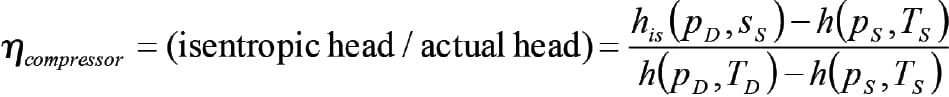 (2)
(2)
Where:
ss = s(ps, Ts)
h(p,T) = enthalpy (heat content) of gas
h is (pD, ss) – h(ps, Ts) = isentropic enthalpy change of gas
s(p,T) = entropy of gas (a thermodynamic quantity representating unvailable energy; Necessarily increases with turbomachinery process due to frictional losses
m•compressor = compressor mass flowrate
Along with selecting the specific measurement sensors and determining their placement, preparation for the field performance test should also include the following items:
- Defining the operating conditions to be used for the test points
- Selecting the approach for data reduction and test uncertainty. The accuracy of calculated compressor performance depends on measurement uncertainty in the inlet and exit pressures and temperatures, gas composition, and mass flowrate. Uncertainties in performance can range from less than 0.5% in laboratory tests [6] to 2–3% or more in field measurements [7]. Overall measurement uncertainty depends on a large number of factors, including sensor accuracy and calibration, proper probe installation, signal conditioning, flow non-uniformity or unsteadiness, and heat loss from the system.
- Specifying the ultimate objective of the test. For example, in the case of an acceptance test, the field performance test results will be used as an acceptance criterion. In cases where the performance test data will be used for maintenance scheduling, engineers should specify how the data will be compared to previous measurements for equipment aging practices.
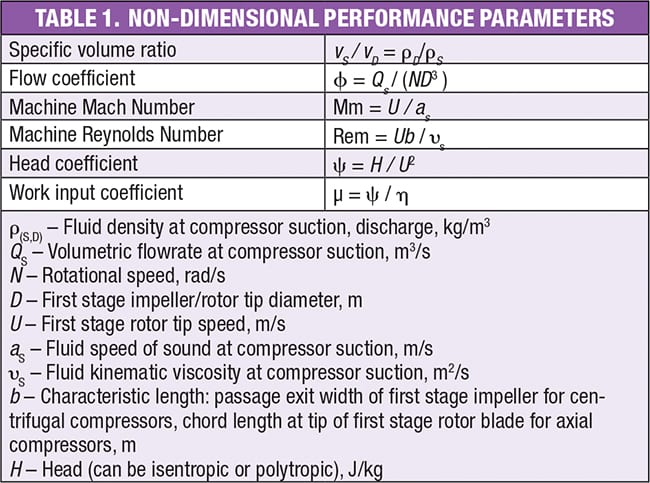
When making a comparison between current and previous field measurements, it is important to recognize that measurements taken at different operating conditions cannot be directly compared. Therefore, it is necessary to either ensure that exactly the same operating conditions are duplicated for the two sets of measurements, or that there are non-dimensional parameters that can be used for comparing the data from tests taken under different operating conditions.
The six most common non-dimensional performance parameters used for centrifugal compressors are the specific volume ratio, Machine Mach and Reynolds numbers, and the head, flow and work input coefficients. These terms are defined in Table 1. Test conditions that closely match the specific volume ratio and flow coefficient are expected to produce similar results for the head coefficient and work input coefficient, with some variation due to different Mach and Reynolds numbers. These variations can be minimal or can be corrected based on test standards if the Mach and Reynolds number deviations are within allowable limits.
Example plots showing measured isentropic head coefficient efficiency versus flow coefficient are provided in Figure 4 for a single centrifugal compressor stage that was tested at multiple Machine Mach numbers (MU2). The predicted curves (solid lines) compare reasonably well with the measured curves (dashed lines), although the peak head and choke flow measurements are both below predicted values, and efficiencies near the design flow coefficient of 0.08 exceed predictions. The results for head coefficient show a typical characteristic of increasing head rise at lower flowrates, with a zero slope at low flow (surge point). The choke line at high flow is shown to be a strong function of the Machine Mach number. The normalized efficiency results show peak efficiencies near the design flow coefficient regardless of Machine Mach number, and also highlight reduced efficiencies and lower choke flow at high Mach numbers.
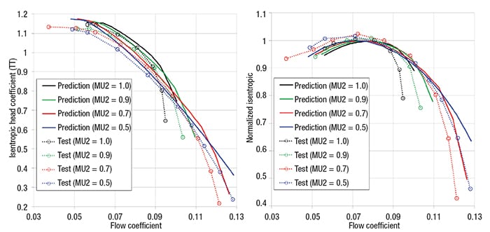
Figure 4. The graphs show example performance data for a centrifugal compressor [5]
Concluding remarks
Field-performance tests can benefit compressors in all stages of equipment life. For new units, performance tests can validate product performance, while for existing units, performance tests can help to monitor for maintenance practices. In addition, performance can be used to determine an end-of-life metric.
Centrifugal compressor performance metrics are based primarily on measured temperatures, pressures, flows and gas compositions, as well as an appropriately selected equation of state. Careful selection and placement of measurement transducers are necessary to reduce test uncertainty. Proper planning of the testing is also necessary to define operating conditions and the desired ultimate objective of the test.
Edited by Scott Jenkins
References
- Content in this article was taken from material presented at the 2018 Turbomachinery and Pump Symposium.
- ASME PTC 10-1997, Performance Test Code on Compressors and Exhausters, American Society of Mechanical Engineers, www.asme.org.
- ASME PTC 19-5-2004, Flow Measurement, American Society of Mechanical Engineers, www.asme.org.
- ISO 5389, Turbocompressors – Performance Test Code. International Organization for Standardization, www.iso.org.
- Brun, K., and Nored, M., Guideline for Field Testing of Gas Turbine and Centrifugal Compressor Performance, Release 2.0, GMRC 2006.
- Allison, T.C., Moore, J.J., Rimpel, A.M., Wilkes, J.C., Pelton, R., Wygant, K., Manufacturing and Testing Experience with Direct Metal Laser Sintering for Closed Centrifugal Compressor Impellers, Proceedings of 43rd Turbomachinery Symposium, Houston, September 2014.
- Smith, N.R., Clarke, C., Allison, T.C., Cave, M., and Wilkes, J.C., The Comparison of Aerodynamic Performance Data Acquired from Thermal Measurements and a Torquemeter on a Compressor Impeller, Proceedings of ASME Turbo Expo, Paper #GT2018-77016, Oslo, Norway, June 2018.
- Kurz, R. and Brun, K., On Test Uncertainties in Field Performance Tests, Proceedings of ASME Turbo Expo, Paper #GT2015-42035, Montreal, Canada, June 2015.
Authors
 Nathan Poerner is a senior research engineer in the Fluid Machinery Section at Southwest Research Institute (6220 Culebra Road, San Antonio, TX 78238; Phone: 210-864-5111; Email: nathan.poerner@swri.org; www.swri.org). He holds B.S. and M.S. degrees in mechanical engineering from Texas Tech University. His work experience has primarily been in field measurements and troubleshooting mechanical systems, specifically pulsation and mechanical resonance issues. This work is supported by mechanical and fluid simulations and modeling. Poerner is involved in numerous research projects focused on rotating and reciprocating machinery.
 Tim Allison is the manager of the Rotating Machinery Dynamics Section at Southwest Research Institute (same address as above; Email: tim.allison@swri.org). His research at SwRI includes finite element analysis, modal testing, instrumentation and performance testing for applications including high-pressure turbomachinery, centrifugal compressors, gas turbines, reciprocating compressor valves, high-frequency piping vibration and test rigs for rotordynamics, blade dynamics and aerodynamic performance. He has published over 50 articles on various turbomachinery topics and is an associate editor for the ASME Journal of Engineering for Gas Turbines & Power. He holds a Ph.D. in mechanical engineering from Virginia Polytechnic Institute and State University.
 Hector Delgado leads the Machinery Services group at Southwest Research Institute (same address as above: Email: hector.delgado@swri.org). Delgado received B.S. and M.S. degrees, both in mechanical engineering from the University of Nuevo Leon (Mexico) and University of Texas at San Antonio, respectively. Delgado’s research interests are in the areas of turbomachinery dynamics, root-cause failure analysis and mechanical design. He has significant experience in the study of mechanical vibration, especially related to the applied analysis of the blade and impeller dynamics. His experience also includes diagnosing causes and recommending solutions for machinery reliability improvement, as well as pipeline pulsation and vibration control.