This overview presents guidance for the safe design of piping systems that are used for the distribution of hydrogen gas
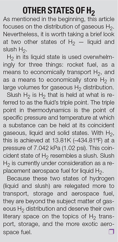 Hydrogen gas is a very volatile fluid that has a high propensity to leak. This is a very dangerous and lethal combination of tendencies, a volatile fluid that is difficult to contain. These are tendencies that need to be taken into consideration when selecting material, gasketing and sealing, as well as the design characteristics of such a system. These topics regarding H 2 gas distribution are the focus of this discussion, not the manufacture of H2, H2 in its liquid state, nor slush H2 (see sidebar, at right).
Properties of H2
The following are a few key points of hydrogen gas and H2-air mixtures that are helpful to know. There are two modes in which H2 gas will burn: by deflagration and by detonation.
Deflagration. Deflagration is the ordinary mode of burning in which the flame travels through the mixture at subsonic speeds. As an example, this happens when a free cloud of H 2 -air mixture is ignited by a small ignition source. In such a case the flame will travel at a rate anywhere from ten to several hundred feet per second. The rapid expansion of hot gases produces a pressure wave whose force is in direct proportion to the size of the cloud. The force of the pressure wave can be strong enough in some cases to damage building structures and other objects in its path and cause injury to personnel.
Detonation. With a detonation, the flame and the shock wave travel through the mixture at supersonic speeds. The pressure ratio across a detonation wave is considerably greater than that found in a deflagration. The hazards to personnel, structures and nearby facilities are greater in a detonation due to the added force. A detonation can build up from an ordinary deflagration when ignited in a confined area. In such a confined area, ignition can be caused by a minimal energy source. But detonation of a H2-air mixture in an unconfined area requires a more powerful ignition source.
The pressure ratio across a detonation wave in a H2-air mixture is about 20. At atmospheric pressure, a ratio of 20 equals 300 psi. When this wave of pressure strikes a fixed object the pressure ratio increases to between 40 and 60. This is due to the pressure wave bouncing back on itself from a fixed obstacle.
Propensity to leak. Due to its low viscosity and low molecular weight, gaseous H2 has a high propensity to leak, and even permeate through or into various materials.
H2 gas is eight times lighter than natural gas, 14 times lighter than air, 22 times lighter than propane and 57 times lighter than gasoline vapor. This means that in an outside installation, H2 gas will rapidly rise and disperse, mitigating any evidence there is even a leak. But this can be a double-edged sword. If welding should be done on an outside installation above or downwind in close proximity of a H2 leak without first performing a leak detection survey prior to welding, there could be a detonation. In an enclosed facility, the H2 gas will rise and accumulate from the ceiling down — a circumstance that allows it to build to a large volume before increasing its chances of coming into contact with an ignition source near the floor level.
Autoignition. Autoignition is the phenomenon in which a mixture of gases or vapors ignites spontaneously with no external ignition source. It is also referred to as “autogenous ignition” or “spontaneous ignition.” Autoignition is dependent upon temperature, not pressure.
The autoignition temperature is the lowest temperature at which a fuel, in contact with air or an oxidizer, will self-heat to ignition without an external ignition source. The autoignition temperature for a monopropellant is the temperature at which it will self-heat to ignition in the absence of an oxidizer. The autoignition temperature of gaseous H2 in air is 585°C.
The ignition energy is the amount of energy needed to initiate flame propagation through a combustible mixture. The minimum ignition energy is the minimum energy required for the ignition of a particular flammable mixture at a specified temperature and pressure. Minimum spark ignition energy for gaseous H2 in air at 1 atm = 1.9×10⁻⁸ Btu (0.02 mJ).
Explosive limits are the maximum and minimum concentrations of vapor, mist, or dust in air or oxygen at which explosions occur. The size and geometry of the environment as well as the concentration of the fuel control the limits. “Detonation limit” is sometimes used as a synonym for “explosive limits.”
The explosive limits for a mixture of H2 in air are 18.3 vol.% (lower limit) and 59 vol.% (upper limit).
Piping materials
In the design of piping systems (Figure 1), one of the first steps in the process will be to determine the material of construction needed for each fluid service. And each fluid service will be categorized in accordance with ASME B31.3 para. 300(b)(1), which states that, “The owner is also responsible for designating piping in Category D, Category M, High Pressure, and High Purity Fluid Services, and for determining if a specific Quality System is to be employed.”
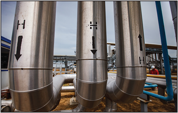
FIGURE 1. Hydrogen pipelines are a common sight at petroleum refineries
Categorizing a fluid service identifies the degree of examination and the types of examination that are required along with a number of other requirements based on a fluid’s category. The owner’s responsibility for this will typically fall to the owner’s engineering department or an outsourced engineer.
And while the B31.3 Process Piping Code does not tell an owner what material to use for specific fluid services, it does give guidance for a material’s strength, thickness and joining requirements. There are also two statements within the Introduction of the Code that are explicit in stating that:
- “It is the owner’s responsibility to select the Code Section that most nearly applies to a proposed piping installation.”
- “The Code is not a design handbook. Many decisions that must be made to produce a sound piping installation are not specified in detail within this Code. The Code does not serve as a substitute for sound engineering judgments by the owner and the designer.”
And to expand on the first bullet point above, B31.3 Para. 300(b)(1) also states that, “The owner of a piping installation shall have overall responsibility for compliance with this Code, and for establishing the requirements for design, construction, examination, inspection and testing that will govern the entire fluid handling or process installation of which the piping is a part.” Having therefore set a few ground rules for responsibilities and the requirement for designating fluid service categories, let’s see where gaseous hydrogen fits into all of this.
Because of, and aside from, its tendency as a leak-prone, volatile fluid, gaseous hydrogen can be, in accordance with B31.3 fluid service categories, considered either a Normal Fluid service or a Category M fluid service. As mentioned above, categorizing a fluid service is the owner’s call, so long as it fits within a selected Category guideline as described in B31.3, para. 300.2 Definitions, under “fluid service.” Following are definitions of both Normal Fluid service and Category M Fluid service:
“Normal Fluid Service: a fluid service pertaining to most piping covered by this Code, i.e., not subject to the rules for Category D, Category M, Elevated Temperature, High Pressure, or High Purity Fluid Service.
Category M Fluid Service: a fluid service in which both of the following apply:
(1) the fluid is so highly toxic that a single exposure to a very small quantity of the fluid, caused by leakage, can produce serious irreversible harm to persons on breathing or bodily contact, even when prompt restorative measures are taken
(2) after consideration of piping design, experience, service conditions, and location, the owner determines that the requirements for Normal Fluid Service do not sufficiently provide the leak tightness required to protect personnel from exposure.”
In the above definition for Category M, gaseous hydrogen does not meet the criteria for item (1) because it is not considered a toxic fluid. But the Code leaves the door open to enable the assignment of a fluid service as Category M by applying paragraph (2) in stating that after due consideration of “…piping design, experience, service conditions, and location…” the owner can indeed make the determination that the requirements for Normal Fluid Service do not sufficiently meet the needs for ensuring a heightened level of integrity in the design, construction, examination, inspection and testing of a gaseous hydrogen piping system.
Hydrogen embrittlement
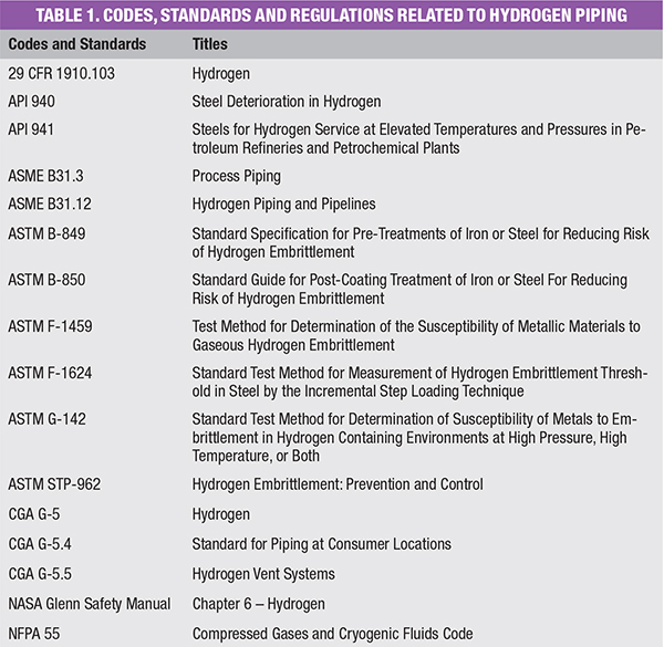
Before touching on high-temperature hydrogen attack (HTHA), please refer to Table 1. In this table are a list of codes, standards, and regulations that include six documents on the topic of hydrogen embrittlement (HE), a generalized corrosion anomaly that includes HTHA. HE can occur at low temperatures and at high temperatures. Considered a form of corrosion, it can be initiated in a number of ways while also affecting a wide range of materials.
HE comes in many forms that can be characterized as hydrogen-assisted cracking (HAC), hydrogen stress cracking (HSC), stress corrosion cracking (SCC), hydrogen-assisted corrosion cracking (HACC), hydrogen blistering (HB), hydrogen induced cracking (HIC), stress oriented hydrogen-induced cracking (SOHIC), step-wise cracking (SWC), sulfide stress cracking (SSC), soft zone cracking (SZC), and high temperature hydrogen attack (HTHA).
Taken to its simplest form, hydrogen embrittlement is the mechanics of failure at the grain boundary of metals, causing a reduction of ductility as a result of the permeation of atomic hydrogen. The means by which this occurs is varied and somewhat identified by the respective titles, such as HTHA, in which the coincident high temperature and high pressure of hydrogen are the requisites for embrittlement, and SSC, in which atomic hydrogen is produced as an off-gas resulting from acid corrosion with the hydrogen then permeating the metal containment to potentially cause embrittlement. But the general result is the same with all of the above hydrogen embrittlement cases in which the strength of a metal is reduced below its allowable stress range through embrittlement, in turn setting the stage for a possible catastrophic event, given the volatility of the fluid.
With regard to material selection for gaseous H2 service, there are two main considerations, beyond that of wall thickness and mechanical joint ratings: 1. high-temperature hydrogen attack (HTHA) and 2. the deep concern regarding leak potential. Both of these topics are now discussed.
HTHA
Atomic hydrogen, as opposed to molecular hydrogen, can propagate, among other ways, by means of hydrogen being put under elevated pressures at elevated temperatures, which sets the stage for potential HTHA. At these conditions, atomic hydrogen is able to diffuse into carbon-steel piping material or equipment, where it reacts with the carbon in solution with the metal to form methane gas at the grain boundaries. Unable to escape, the gas expands to create fissures and cracks in the pipe or vessel wall — this is HTHA. You can see clearly the results of HTHA in Figure 2, where the fissures and cracks are apparent in the wall of the 8-in. nominal pipe size (NPS) section of piping that failed under these conditions.
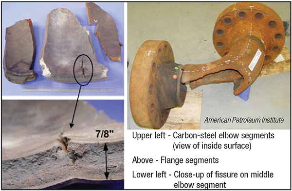
FIGURE 2. Shown here is the damage caused by high-temperature hydrogen attack
Carbon steel is acceptable for use in hydrogen service when operating temperatures remain below 500°F. HTHA occurs, as mentioned above, when hydrogen is contained under high partial pressure in combination with high temperatures. When the partial pressure of hydrogen is expected to be approximately 3,000 psig, at coincidental temperatures above approximately 450°F, which is what the conditions were for the Figure 2 catastrophe, then carbon steel is not recommended.
As can be seen by the modified Nelson diagram in Figure 3, as taken in part from API 941, elevated temperatures have the greatest effect in contributing to hydrogen attack. In selecting carbon steel for use in operating temperatures not exceeding 500°F, the partial pressure of hydrogen can exceed in access of 1,000 psig.
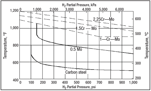
FIGURE 3. This modified Nelson diagram (adapted from API 941) can be used for selecting the right material for hydrogen service at different temperatures
The Figure 3 diagram indicates the choice of steel warranted to avoid hydrogen attack as a function of operating temperature and partial pressure of hydrogen. Austenitic stainless steels are not susceptible to HTHA and are a satisfactory material at all temperatures and pressures.
With a proven track record, the most practical material used in hydrogen service is 316/316L austenitic stainless steel. While it is advised to post weld heat treat (PWHT) carbon steel to bake out any residual hydrogen from the welding process and decrease the post weld hardness in the heat affected zone (HAZ) this is not required for austenitic stainless steel.
Heat treatment and thermal heat effect caused by welding have little effect on the mechanical properties of austenitic stainless steel. However, the mechanical properties, such as strength and hardness of austenitic stainless steels, can be increased by cold working. When bending and forming austenitic stainless-steel pipe, its mechanical properties will be altered, including a reduction in the material’s ductility.
If cold forming is required of austenitic stainless steel, a full solution anneal (heating to around 1,045°C followed by quenching or rapid cooling) will restore the material’s mechanical properties to their somewhat original values. This will also remove alloy segregation, sensitization, and sigma phase realized after cold working. In performing the solution annealing process, you are cautioned that the rapid cooling might well introduce residual stresses back into the material if not done properly.
For a selection of material that is acceptable for H 2 service, Tables GR-2.1.1-1 “Material Specification Index for Piping and Pipe Components” and GR-2.1.1-2 “Material Specification Index for Pipelines” found in ASME B31.12 Hydrogen Piping and Pipelines are a good place to start.
Mitigating leaks
With a standard atomic weight of 1.008 atomic mass units (amu), hydrogen is the lightest and smallest element in the periodic tables, giving it a high propensity to leak; with, I might add, potentially devastating results. It is therefore imperative that a gaseous piping system be designed to limit mechanical type joints and enhance those joints that are truly necessary.
In limiting potential leak points, the system should be entirely welded, with the exception of flanged joints at equipment, inline components and valving. Threaded joints should be avoided as much as possible, if not entirely. If threaded joints cannot be avoided for some reason, it is recommended that they be fully engaged without thread sealant then seal welded. Piping joints should be buttwelded, and post-weld heat treatment (PWHT) when carbon-steel pipe is used. After welding, pipe within the heat-affected zone (HAZ) becomes susceptible to hydrogen attack, even at ambient temperatures. And while hydrogen attack mainly occurs at elevated temperatures, the PWHT step will reduce, if not eliminate, that possibility entirely, even at ambient conditions.
The weak point in an all-welded system will be the flange joint. In order to provide a high degree of integrity at flanged joints, the Kammprofile gasket (Figure 4), or some form of that gasket design, should be considered. Manufactured in much the same way by multiple manufacturers, it is a very forgiving gasket. It consists of a serrated solid metal ring sandwiched between a soft, deformable sealing material. The serrations concentrate bolt load on a smaller area to provide a tight seal at lower stress. Its design allows it to compensate for irregularities in the flange surfaces as well as fluctuations in service conditions.

FIGURE 4. Kammprofile gaskets come with a metal core bonded with a soft filler material on both sides. After installation, the soft non-metallic filler gets pushed into the metal core serrated grooves to provide good sealing
Another consideration in system integrity is the valving. Leaks around valve stem packing and body flanges is a real concern. In an effort to prevent this, the selection of bellows seal valves are recommended.
Using a 1-in. sch. 80 carbon steel pipe, in our following example, per ASTM A106 Gr B with allowance for manufacturing tolerance, corrosion, and mechanical allowances the maximum allowable working pressure (MAWP) can be calculated for temperatures up to 300°F in a two-step process. (Note: The reason it states, “…for temperatures up to 300ºF…” is due to the fact that the allowable stress (S) for ASTM A106 Gr B material begins to deteriorate when the temperature exceeds 300ºF. (S), in Equation (1) would therefore need to be adjusted for temperatures above 300ºF.)
Referring to Equation (1), the first step requires calculating for the theoretical burst pressure of the pipe.
P = (2 × T × S)/ D(1)
Where:
D = Outside diameter of pipe, in.
P = Burst pressure, psig
Pa = Maximum Allowable Working Pressure (MAWP), psig
S = Maximum allowable stress for the material at design temperature, psi
T = Pipe wall thickness minus mechanical allowance, corrosion allowance, and manufacturing tolerance, in.
The second part of the process is to calculate for the maximum allowable working pressure, Pa, for the pipe by applying a safety factor, S f, against the results for P in accordance with Equation (2):
Pa = P/Sf (2)
Therefore, in using the 1-in. sch. 80 material mentioned above, the calculation for the burst pressure would look like the following:
P = (2 × 0.107 × 20,000)/1.315
= 3,254 psig
= Theoretical burst pressure
By then applying a safety, Sf, of 4, as recommended in the ASME Pressure Vessel Code Section VIII-1 2019, para. UG-101, the calculation would look like the following:
Pa = 3,254/4 = 813.5 psig, or say 810 psig MAWP
The resulting 810 psig MAWP applies to the pipe only. The flange joints, or the lowest rated component in the system will be the governing factor in determining the allowable pressure for the system.
Based on ASME B16.5, at temperatures from –20°F to 100°F, the Class 150 carbon-steel flange joint has a maximum allowable working pressure of 285 psig. Class 300 has a maximum allowable working pressure of 740 psig. This will be the limiting pressure-containing factor for the system as per the following material specification example. And additionally, those values can be exceeded by a factor of 1.5 for hydrotesting only.
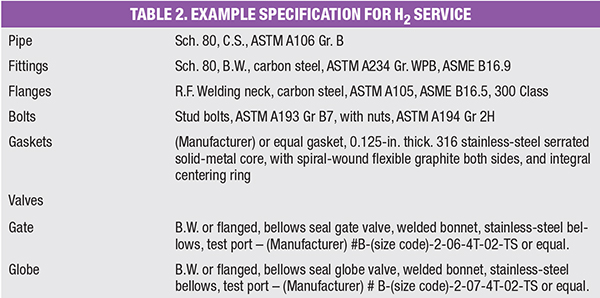
Example specification
As an example for a basic carbon-steel material specification, a pipe specification for gaseous H2 service operating at ambient temperatures with design pressures below 740 psig might consist of the material requirements shown in Table 2. The following are the types of notes that might be included in the specification:
- Examination shall include 100% radiography or ultrasonic examination of all welds.
- Installation should minimize or eliminate the use of breakout flanges. Flange joints should only exist at flanged equipment, including instruments, and flanged valves.
- When a carbon-steel-to-carbon steel threaded connection is required, do not apply thread compound during assembly. Seal-weld after full thread engagement.
- Examine 100% of buttwelds by non-destructive testing (NDT) methods, such as radiography or ultrasonic, prior to PWHT. Document the examination process.
- Welds shall be post weld heat treated. PWHT is required to prevent HTHA of the pipe weld seam and material around the heat affected zone at weld joints. The service provider shall provide documentation of the PWHT process. As an alternative, weld metal hardness controls can be put in place such that the maximum weld metal hardness in carbon steel is equal to or less than 200BHN and weld procedure qualification testing shall be done to ensure that the hardness of the heat-affected zone (HAZ) at each weld does not exceed 248 VHN (reference: NACE RP0472).
- The maximum design limit is based on the weakest component in the system. It is not based strictly on the maximum temperature or maximum pressure of the component, but on the highest allowable coincident of the two.
Honorable mention
There are many elements, other than the pipe itself, that make up a piping system, such as fittings, valves, inline equipment, and so on. And while many of these items would be incorporated to make up a piping system to discuss them at length would require more pages than this article can accommodate.
Having said that, the same information found in this article can also be applied to the fittings, valves and inline equipment that make up a gaseous hydrogen piping system.
Leak testing
When installing a piping system for a material as potentially volatile as H2 a procedure for leak testing should be established that not only sets forth thorough and definitive guidelines, but also identifies the best suitable means of assuring system integrity.
Part of that assurance lies with the leak testing procedure. Using a two-step procedure wherein the first step is a pneumatic leak test for pressure integrity followed by a sensitive leak test for leak integrity. Both tests are in accordance with ASME B31.3, ensuring the integrity of the joints with a close approximation of the H2 service gas and its leak potential.
Aside from hydrogen’s potential volatility, its molecular size, with an atomic mass of 1.008 amu, creates a containment problem. (The reason for the follow-up sensitive leak test.) Helium, with an atomic mass of 4.002602 amu, provides a very close approximation of that containment problem. Nitrogen, with an atomic mass of 14.00674 amu, would not provide the same assurances found when using helium as the test gas. I would recommend against using a heavier gas for the leak test, such as nitrogen, by then extrapolating the results of a nitrogen leak rate to determine what the leak rate might be if it were H2.
When testing potentially volatile or lethal piping systems for leaks, a maximum allowable leak rate should be predetermined and specified. The quantitative aspect of the accumulation of H2 from a leak can be assessed under two separate criteria:
1. Is the piping inside a building?
a. Is the building well ventilated?
b. Are there any potential ignition sources within close proximity to the piping?
c. Is the piping in an area that could pocket and accumulate hydrogen emission?
2. Is the piping in open air?
a. Are there potential ignition sources within close proximity to the piping?
Two different acceptable leak rates could be established for inside piping systems and outside piping systems. The high diffusion rate of helium makes it difficult to test for minute quantities of helium on an inside installation, and even more difficult on an outside installation. For that reason, and because H2 would probably not have a place to accumulate outside, a higher leak rate could be tolerated for an outside installation.
Detecting leaks can be accomplished with a soapy water solution like Snoop. However, this is not the best method for locating the relatively small leaks that could occur with helium. Nor does it provide a means to quantify the leak rate.
Using a helium probe (spectrometer), leak rates can be determined to a level of 10–6cm3/s. This allows leaks to not only be located but to be quantified as well. Determining and specifying the maximum allowable leak rate for gaseous hydrogen is a plant- or owner-specific issue that is based on a plant by plant circumstance.
If it is determined that a single maximum allowable leak rate would apply to both inside and outside installations, then the basis for a worse case inside installation would determine the maximum allowable leak rate. In making that determination, a scenario would have to be created whereas a leak would occur at a joint, at an assumed leak rate, inside a building, in still air, with a vaulted or penthouse-type ceiling; a space above the leak where H2 could accumulate.
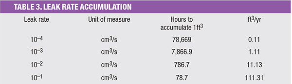
Assuming good design practices have been followed, the main concern regarding this discussion is with a gaseous H2 discharge from a leak accumulating in an enclosed building. Table 3 lends some perspective when assessing the magnitude of a given leak rate.
When setting a value for an allowable leak rate, it should be assumed that good design practices may not be adhered to. Even though a good design, particularly where H2 is concerned, would not allow a building to be designed without good ventilation, and would not allow a penthouse type ceiling without ventilation, it should be assumed otherwise; a worst case scenario, if you will.
As a reference, ASME B31.3 – Process Piping provides for a Sensitive Leak Test in Para. 345.8, subparagraph 345.8.2 Method, in which it states that, “The test shall be the Bubble Test — Direct Pressure Technique in accordance with ASME BPVC, Section V, Article 10, Mandatory Appendix I or another leak test method that has a demonstrated sensitivity not less than 10−3 std. mL/s under test conditions.”
Final remarks
Whether you’re designing a low-pressure gaseous H2 distribution system at ambient temperatures or a resid-hydrotreater system operating in the neighborhood of 3,000 psig at 600°F, engineering and construction need to go into it with a good understanding of the many risk nuances that H2 brings to the table.
As mentioned a number of times, H2 is very volatile and unforgiving. Do the design and construction as if you were the one who had to work around such a system every day. That kind of mindset brings a whole new perspective to what you are doing.
The list of codes, standards and a regulation in Table 1 provide a wealth of information regarding the design and construction of hydrogen piping systems. I would recommend gaining access to the information contained in these volumes prior to getting involved with designing and constructing a H2 system. Understanding the nuances in H2 piping design helps you avoid the pitfalls you might otherwise overlook.
Author
 W. M. (Bill) Huitt has been involved in industrial piping design, engineering and construction since 1965. Positions have included design engineer, piping design instructor, project engineer, project supervisor, piping department supervisor, engineering manager and president of W. M. Huitt Co. (P.O. Box 31154, St. Louis, MO 63131-0154; Phone: 1-314-966-8919; Email: wmhuitt@aol.com; Website: www.wmhuittco.com), a piping consulting firm founded in 1987. His experience covers both the engineering and construction fields and crosses industry lines to include petroleum refining, chemical, petrochemical, pharmaceutical, pulp & paper, nuclear power, biofuel and coal gasification. He has written numerous specifications, procedures on design and construction, guidelines, papers, and magazine articles on the topic of piping design and engineering. Huitt has also written “Bioprocessing Piping and Equipment Design – A companion guide for the ASME BPE Standard.” He is a past member of ISPE (International Society of Pharmaceutical Engineers), CSI (Construction Specifications Institute) and a current and active member of ASME (American Society of Mechanical Engineers). He is a member of the B31.3 section committee, Chair of B31.3 Subgroup H on High Purity Piping, Vice Chair of ASME BPE subcommittee on Certification, a member of three other ASME-BPE subcommittees and is active on several Task Groups. Huitt is also a member of the ASME Board on Conformity Assessment for BPE Certification, a member of the A13 Standards Committee for Standard A13.1 Scheme for the Identification of Piping Systems, a member of the API (American Petroleum Institute) Task Group for RP-2611, and he serves on two corporate specification review boards. He has also authored the training program and provides training to ASME consultants for auditing fitting manufacturers applying for ASME BPE Certification.