Expanders can take advantage of pressure reductions to drive rotating machines. Information on how to assess the potential benefits of installing expanders is provided here
Often in the chemical process industries (CPI), “a considerable amount of energy is wasted in pressure control valves, where high-pressure fluids must undergo a pressure reduction” [1]. Depending on various technical and economic factors, it may be feasible to transform this energy into rotational mechanical energy that can be used to drive an electrical generator or another rotating machine. In the case of incompressible fluids (liquids), this is accomplished by using hydraulic power-recovery turbines (HPRTs; explained in Ref. 1). For compressible fluids (gases), expanders are the appropriate machine.
Expanders are a mature technology with a host of successful applications, such as fluid catalytic cracking (FCC), refrigeration, natural-gas city gate-valve stations, air separation or off-gas venting, to name a few. Basically, any gas stream subject to a pressure reduction can be used to drive an expander, yet “the energy output is proportional to pressure ratio, temperature and flowrate of the stream” [2], and the technical and economic feasibility of implementing expanders in a process depends on these and other factors, such as the local price of energy and the availability of suitable machines from manufacturers.
While turboexpanders (which function in a manner similar to that of turbines) are the best-known type of expander (Figure 1), there are other types suitable for different process conditions. This article describes the main types of expanders and their components, and summarizes how operations managers, consultants or energy auditors in various sectors of the CPI can assess the potential economic and environmental benefits of an expander installation.
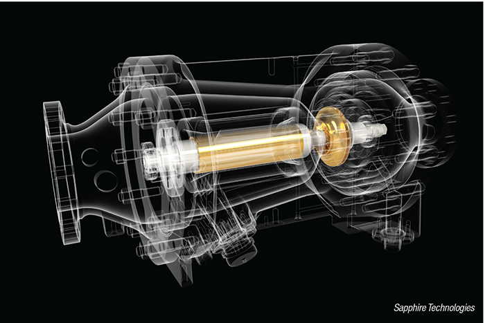
Figure 1. This image shows a three-dimensional rendering of an inline turboexpander
Expander types
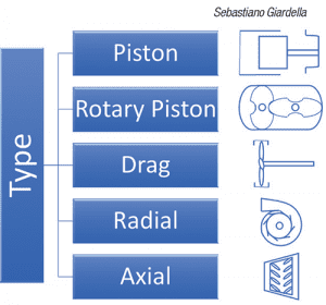
Figure 2. Different types of expanders vary widely in their geometries and their capabilities
There are many different types of expanders, varying widely in geometry and capability. The main types are shown in Figure 2, with a brief description of each given below. Further details and a chart comparing the operating regimes of each of these types as a function of specific diameter and specific speed can be found in Ref. 3.
Piston turboexpander. Piston and rotary-piston turboexpanders operate like backward combustion engines, taking high-pressure gas and converting its stored energy into rotational energy through a crank shaft.
Drag turboexpander. Drag turboexpanders consist of a concentric flow cavity with scoop-shaped fins fixed to the periphery of the rotating element. These are designed much like a water wheel, but the concentric cavity gradually increases in cross section from inlet to outlet, allowing for expansion of the gas.
Radial turboexpander. Radial turboexpanders are designed with axial-flow inlets and radial-flow outlets, such that the gas is expanded radially through the turbine wheel. Similarly, axial-flow turbines expand gas through the turbine wheel, but the direction of flow remains parallel with the axis of rotation.
The main focus in this article is on radial and axial turboexpanders, discussing their various subtypes, components and economic benefits.
Turboexpanders recover energy from high-pressure gas streams and convert the energy to drive a load. Generally, the load is either a shaft-coupled compressor or an electric generator. Compressor-loaded turboexpanders compress a fluid in other parts of the process stream requiring a compressed fluid, and thus increase the overall plant efficiency by utilizing otherwise wasted energy. Generator-loaded turboexpanders convert the energy into electricity, which can be used in other plant processes or returned to the local electrical grid for sale.
Turboexpander generators can be configured with a direct-drive shaft from the turbine wheel to the electric generator or through a gearbox, which effectively reduces the input speed from the turbine wheel to the generator through a gear ratio. Direct-drive turboexpanders are superior in terms of efficiency, footprint and maintenance costs. Gearbox turboexpanders are much heavier and require a larger physical footprint, auxiliary oil lubrication equipment and regular maintenance.
Flow-through turboexpanders can be designed with radial or axial turbines. Radial flow-through expanders contain an axial inlet and a radial outlet such that the gas flow exits the turbine radially from the axis of rotation. Axial flow turbines allow the gas to flow axially along the axis of rotation. Axial turbines extract energy from the gas flow via inlet guide vanes to the expander wheel, while the cross-sectional area of the expansion chamber gradually increases to maintain constant velocity.
Components
A turboexpander generator has three primary components: turbine wheel, specialized bearings and generator.
Turbine wheels. The turbine wheels are typically designed specifically for the application, in order to optimize aerodynamic efficiency. Application variables affecting turbine wheel design include inlet/outlet pressure, inlet/outlet temperature, amount of volumetric flow and fluid characteristics. Turboexpanders with several turbine wheels are required when the pressure ratio is too large to reduce via a single stage. Both radial and axial turbine wheels can be designed with multiple stages, but the axial turbine wheel has a much shorter axial length and thus is more compact. A radial multi-stage turbine requires the gas to flow from axial to radial, then back to axial again, and thus produces higher friction losses than the axial turbine.
Bearings. Bearing design is critical for efficient turboexpander performance. Bearing types associated with turboexpander designs vary widely and can include oil lubrication, fluid film, conventional ball and magnetic. Each has its own advantages and disadvantages, as summarized in Table 1.
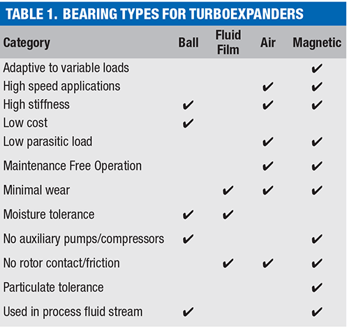
Many turboexpander manufacturers are transitioning to magnetic bearings as the “bearing of choice,” due to their distinct advantages. Magnetic bearings provide frictionless operation for the dynamic components of the turboexpander, dramatically reducing operating and maintenances costs over the life of the machine. They are also designed to adapt to a wide range of axial and radial loads and surge conditions. Their higher upfront costs are offset by much lower lifecycle costs.
Generator. The generator takes the rotational energy from the turbine and converts the energy into useable electricity through an electromagnetic generator, which can be either an induction or permanent magnet (PM) generator. Induction generators are rated for lower speed, and thus require gearboxes for high-speed turbine applications, but are capable of being designed to match the frequency of the grid, thereby eliminating the need for a variable frequency drive (VFD) to transfer the generated electricity. PM generators, on the other hand, can be directly shaft-coupled to the turbine, and can deliver electricity to the grid via a VFD. The generator can be designed to output the maximum amount of electricity according to the available shaft power of the system.
Seals. Sealing is also a critical component in designing a turboexpander system. To maintain high efficiency and meet environmental standards, systems must be sealed to prevent potential process gas leaks. Turboexpanders can be designed with dynamic or static seals. Dynamic seals, such as labyrinth seals and dry gas seals, provide sealing around the rotating shaft, usually between the turbine wheel and the rest of the machine where the bearings and generator are located. Dynamic seals wear over time and require regular maintenance and inspection to ensure they are working properly. Static seals may be used when all components of the turboexpander are contained inside one housing, protecting any lead wires exiting the housing, including leads for generators, magnetic bearing actuators or sensors. These hermetic seals provide permanent protection against gas leaks and do not require any maintenance or servicing.
Expander process arrangement
From a process point of view, the basic requirements for an expander installation are a high-pressure compressible (non-condensable) gas being delivered to a lower-pressure system at a sufficient flowrate, a pressure differential and a use factor to maintain the equipment’s working parameters within safe and efficient levels.
From a pressure-reduction function, expanders can be used to replace a Joule-Thomson (J-T) valve, also known as a throttling valve. Given that the J-T valve follows an isenthalpic path, whereas the expander follows a nearly isentropic path, the latter reduces the gas enthalpy, with the enthalpy difference being transformed to shaft power, achieving a lower outlet temperature than the J-T valve. This is useful in cryogenic processes aiming to reduce the temperature of the gas.
In cases where there is a lower limit to the outlet-gas temperature (for example, in pressure letdown stations, where the temperature of the gas must remain above freezing, hydrate-formation or minimum design-material temperature), at least one heater is added to control the gas temperature. When a pre-heater is located ahead of the expander inlet, part of the energy supplied to the gas is also recovered in the expander, thus increasing its power output. In some configurations where outlet temperature control is essential, a second post-heater can be installed after the expander to ensure a faster control.
A simplified diagram of the overall process arrangement for an expander generator with a preheater used to replace a J-T valve is shown in Figure 3.
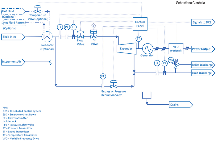
Figure 3. The diagram shows an example of an overall process arrangement for an expander generator
In other process configurations, the energy recovered in the expander can be directly transferred to a compressor. These machines, sometimes referred to as “companders,” typically have the expander and compression stages linked via one or multiple shafts, which may also include a gearbox to adjust for speed differences between both stages. It may also include an additional motor to supply more power to the compression stage.
Described below are some of the most important components that ensure the proper operation and stability of the system.
Bypass or pressure-reduction valve. A bypass valve allows service continuation when the turboexpander is taken out of service (for example, to perform maintenance or during an emergency), whereas a pressure-reduction valve is used in continuous operation to deliver excess gas, when the total flow exceeds the expander design capacity.
Emergency shutdown (ESD) valve. An ESD valve is used to stop gas flowing into the expander during a contingency to prevent mechanical damage.
Instruments and controls. Important variables to monitor include inlet and discharge pressures, flowrate, rotational speed and power output.
Overspeed trip. This device shuts off the flow to the turbine, which causes the turbine rotor to decelerate, protecting the equipment from an excessive speed derived from unexpected process conditions that could damage the equipment.
Pressure safety valve (PSV). A PSV is usually installed downstream of the turboexpander to protect the low-pressure line and the equipment. The PSV must be sized for the worst contingency, with typical cases including bypass valve failure open. In cases where the expander is added to an existing pressure let-down station, the process design team should determine if the existing PSV already provides adequate protection.
Preheater. A preheater compensates for the temperature decrease caused by passing gas through the turbine, making it necessary to preheat the gas. Its main role is to increase the temperature of the upstream flow to maintain the temperature of the gas at the expander discharge above minimum values. The temperature increase has the added benefit of increasing power output while also avoiding corrosion, condensates or hydrates that can have a detrimental effect on the nozzle of the equipment. In systems containing heat exchangers (such as the one shown in Figure 3), gas temperature is typically controlled by regulating the flow of heating fluid to the preheater. In some designs, a fired or electric heater may be used instead of a heat exchanger. In existing J-T valve stations, a preheater may already exist, and the addition of an expander may not require further preheaters to be installed, but rather an increase in heating-fluid flowrate.
Lube oil and seal gas systems. As described above, expanders may use different seal designs, which may require lube oil and seal gas. Where applicable, the lube oil must be maintained at high quality and purity as it encounters process gas, and the viscosity levels of the oil must be maintained within the required operation ranges of the oil bearings. A seal gas system generally accompanies a lube oil installation to prevent the oil from the bearing housing from entering the expander housing. In the particular case of companders for use in the hydrocarbons industry, it is common to design lube oil and seal gas systems to API 617 [5] Part 4 specifications.
Variable frequency drive (VFD). When the generator is asynchronous, a VFD is typically included to adjust the alternating current (a.c.) signal to match the frequency of the grid. Typically, designs that rely on VFDs have higher overall efficiencies than those with gearboxes or other mechanical components. Systems based on VFDs also can accommodate a wider range of process variations that may result in varying expander shaft speeds.
Gearbox. In some expander designs, a gearbox is used to reduce the rotational speed of the expander to match the generator’s nominal rotational speed. The use of a gearbox comes at the expense of a reduction in overall efficiency, and hence output electrical power.
Expander process design
When preparing a request for quotation (RFQ) for an expander, process engineers must first define the service conditions, including the following information:
- Operating conditions (inlet and outlet pressure, differential pressure, flowrate, inlet temperature)
- Fluid properties (including gas composition, molecular weight, viscosity, specific heats ratio, dewpoint, presence of corrosive or condensable components)
- Design conditions (inlet and outlet design pressure, design temperature and rating)
- Site and utility data (location, elevation, atmospheric conditions, utility conditions, such as electricity, cooling fluid, instrument air or steam or heating fluid). Where multiple operating cases are foreseen, process engineers should clearly identify these cases, as well as extremes of process parameters (for example, minimum and maximum inlet pressure) and provide process data for each. They may also provide a sketch of the proposed facilities, such as a process flow diagram (PFD) or piping and instrumentation diagram (P&ID)
Mechanical engineers typically complete the expander generator data sheets and specifications with the inputs from other engineering disciplines. These inputs may include the following:
- Design code requirements
- Electrical area classification
- Electrical and instrumentation requirements
- Civil/structural design with seismic and wind design data
The specifications should also include a list of documents and drawings to be supplied by the manufacturer as part of the bidding process and as part of the scope of supply, along with test procedures, as applicable, according to project requirements.
Technical information to be provided by the manufacturer as part of the bidding process should typically include the following items:
- Predicted performance (hydraulic power, power output at generator terminals, outlet gas conditions) at each specified case
- Performance curves, utility requirements and auxiliary electrical consumption
- Preliminary drawings
- Technical description
- Scope of supply
- A list of spare parts
- A list of engineering deliverables to be supplied and warranties
If any aspects of the proposal differ from the original specifications, then the manufacturer should also provide a list of deviations along with the reasons for the deviations.
The project design team, upon receipt of the proposals, must then check compliance with the RFQ, and determine whether any deviations are technically justifiable.
Other technical considerations that should be taken into account when evaluating proposals include the following:
- Space and utility requirements
- Warranties offered
- Lead times
- Operational limits
- Technical support and remote monitoring capabilities
- Past performance
- Maintenance requirements
- Other criteria as valued by the project team
Finally, an economic analysis should be performed. Since different options may present different initial costs, it is recommended to perform a cash-flow or lifecycle-cost analysis to compare long-term project economic performance and return on investment. For instance, a higher initial investment can be compensated in the long run by better performance or by reduced maintenance requirements. For guidance on this type of analysis, see Ref. 4.
Calculating power potential
All turboexpander generator applications require an initial calculation of total power potential to determine the total amount of available energy that can possibly be recovered in a specific application. For turboexpander generators, the power potential is calculated as an isentropic (constant entropy) process. This is an ideal thermodynamic case considering a frictionless, reversible adiabatic process, but it is the proper process for estimating realistic power potential.
Power potential is dependent on the following input parameters:
- Gas composition
- Inlet pressure, kPa-gage
- Exit pressure, kPa-gage
- Inlet temperature,°C
- Normalized volumetric flowrate (0°C and 1 atm), Nm3⁄h
The isentropic power potential (IPP) is calculated by taking the difference between the specific enthalpy between the inlet and exit of the turboexpander, and multiplying the result by the mass flowrate. This power potential will be expressed as an isentropic value (Equation (1)):
IPP = ( hinlet – h(i,e)) × ṁ x ŋ (1)
Where, h(i,e) represents the specific enthalpy, considering isentropic exit temperature, and ṁ is mass flowrate.
Although the isentropic power potential is useful in estimating power potential, all real-world systems contain friction, heat and other auxiliary energy losses. Thus, a realistic power potential calculation should consider the following additional inputs:
- Desired exit temperature, °C
- Total turboexpander system efficiency, %
In most turboexpander applications, the temperature is limited to a minimum value to prevent unwanted issues, such as freezing pipelines, as mentioned previously. In the case of natural gas flow, hydrates are almost always present, which means the pipes downstream from a turboexpander or J-T valve will freeze internally and externally if the exit temperature drops below 0°C. Freezing causes restrictions in flow and eventually downtime to defrost. Thus, a “desired” exit temperature is used to calculate a more realistic power potential scenario. However, for gases such as hydrogen, temperature limitation is much lower because hydrogen does not change phase from gas to liquid until it reaches cryogenic temperatures (–253°C). Specific enthalpy is calculated using this desired exit temperature.
Turboexpander system efficiency must also be considered. System efficiency can vary widely depending on the technology being used. For example, a turboexpander that utilizes a step-down gearbox to transmit rotational energy from the turbine to generator will experience far greater friction losses than a system that uses a direct drive from the turbine to the generator. Total turboexpander system efficiency is expressed as a percentage and is considered when estimating actual turboexpander power potential. The realistic power potential (PP) calculation is as follows:
PP = ( hinlet – hexit) × ṁ x ŋ (2)
Where:
h(i,e) = specific enthalpy, considering isentropic exit temperature
ṁ = mass flowrate
ŋ = turboexpander system efficiency
Example 1: Natural gas PP calculation
Let’s consider a natural-gas pressure let-down application. Company ABC runs and maintains a pressure let-down station that delivers gas from a main pipeline and distributes the gas to a local municipality. At this station, inlet gas pressure is 40 bar, while the exit pressure is 8 bar. The inlet temperature of the gas with pre-heating is 35°C, and the gas is pre-heated to prevent freezing pipelines. Thus, the exit temperature of the gas should be controlled such that it will not drop below 0°C. In this example, we will use 5°C as a minimum exit temperature to add a factor of safety. The normalized volumetric flowrate of the gas is 50,000 Nm3/h. To calculate power potential, we will assume all the gas flows through the turboexpander and calculate a maximum power output. The following calculation is made to estimate the total output power potential:
Natural gas mixture:
- Methane: 95.1%
- Nitrogen: 0.1%
- CO2: 2.5%
- Ethane: 3.3%
- Propane: 0.6%
- Isobutane: 0.1%
- Butane: 0.1%
- Inlet pressure: 40 bar (4,000 kPa-gage)
- Exit pressure: 8 bar (800 kPa-gage)
- Inlet temperature: 35°C
- Exit temperature: 5°C
- Normalized volumetric flowrate (0°C and 1 atm): 50,000 Nm3 ⁄h
- Turboexpander system efficiency: 93%
The power potential available in this case is 342 kW at 5°C. The isentropic power potential is 1,754 kW, which indicates that further optimization may be considered. Further optimization may include increasing the temperature of the inlet gas stream by providing additional pre-heating. Doing so will increase the amount of recoverable energy from the stream, but it only makes sense if the spark spread is significant enough for a beneficial economic case. The spark spread is the difference between the wholesale price of electricity and its cost of production using natural gas.
Example 2: H2 PP calculation
Another applicable gas for turboexpanders is H2. With the global energy industry looking more at hydrogen as a long-term clean-energy solution, development of a H2 infrastructure is rapidly growing. As with natural gas, H2 pressure is transmitted at high pressures and let down at specific locations for production, storage and consumption. The distinct pressure let-down cases for H2 are the cryogenic liquefaction process from liquid transportation to gas storage, from gas storage to gas distribution and from gas distribution and local transportation to consumption. During the hydrogen liquefaction process, H2 is compressed and cooled to its inversion point, where the temperature is further reduced while the gas expands to finally reach its liquefaction temperature of –253°C. This liquefaction process allows efficient, high density transportation of H2 throughout its infrastructure.
Consider a H2 fueling station example where gaseous H2 is transferred from a fuel tanker to a storage tank. In this case, hydrogen’s storage pressure in the tanker is 275 bar with a temperature of 60°C. The storage tank required pressure is 18 bar. The gaseous H2 is dispensed into the filling station storage tank at a rate of 5,000 Nm3/h. The trailer is emptied in 3.5 hours, with a turboexpander operating during the first half of this timeframe, while a compressor operates during the second half.
- Process fluid: gaseous H2
- Inlet pressure: 275 bar (27,500 kPa-gage)
- Exit pressure: 18 bar (1,800 kPa-gage)
- Inlet temperature: 60°C
- Exit temperature: not critical
- Normalized volumetric flowrate (0°C and 1 atm): 5,000 Nm3 ⁄h
- Turboexpander system efficiency 93%
The power potential available from Equation (2) is 318 kW and would be dispensed into the storage tank at a temperature of –124°C. In this case, the power produced would be returned to the electrical grid or to provide supply for the immediate facility. During the second half of the emptying process, the compressor will be activated to fully dispense the hydrogen from the tanker. This case is an example of a net-zero process. Using a turboexpander, we can recover energy losses and offset electrical requirements and CO2 emissions.
Example 3: Economic case
Recovery of lost energy through turboexpanders is beneficial to overall plant efficiency, and it offsets electrical requirements and reduces CO2 emissions, but decisions on whether or not to use a turboexpander must include a financial component of the equation as well. Installation of a turboexpander is a capital expenditure (CAPEX), so the payback period should be carefully evaluated to ensure the CAPEX makes financial sense. There may also be potential government incentives for offset of CO2 emissions and sale of electricity to the grid. These variables are the building blocks for a valuable economic case for a turboexpander. To build a simple and straightforward economic case, the following inputs and outputs should be considered:
Inputs:
- Technical specifications (pressures, temperatures, flowrate and so on)
- System purchase price
- System installation price
- Wholesale price of electricity
- Price of natural gas (for pre-heating in natural gas PLD)
- Plant capacity factor (what percentage of a day does the plant run?)
Outputs:
- Payback period
- Electricity produced
- CO2 emissions offset
- Annual revenue
Using the natural gas example from company ABC (Example 1), we can build an economic case for the purchase and installation of a turboexpander. First, we look for market availability of a turboexpander with the appropriate power production for our application. In this example, we will use a 280-kW turboexpander. The price for this system is $300,000 and the installation costs are $50,000. The wholesale price of electricity for the region where this plant is located is $0.16/kWh, while the price of natural gas for pre-heating is $0.06/kWh, bringing the spark spread to $0.10/kWh. The plant operates about 20 hours per day, which we will round to 85% of the day, with an average flowrate of 50,000 Nm3/h.
We will need to optimize the flow through the turboexpander to achieve maximum power production. Since there is 342 kW of available power, we will divert 41,000 Nm3/h of flow through the turbo-expander, while the remaining 9,000 Nm3/h flows through the pressure-reduction valve.
Based on the power production and wholesale price of electricity, we will generate a total of $334,000 per year of electrical revenue. The cost for pre-heating the gas from 20°C to 35°C is $175,000 per year. Subtracting the two, we get a net revenue after pre-heating of $159,000 per year. To calculate the payback period, we divide the CAPEX ($350,000) by the net revenue, yielding a payback period of 2.2 years. This amounts to quite an expeditious payback period for a capital expenditure.
The annual electricity produced can be calculated by multiplying the kilowatt-electric produced by the number of hours per day times the number of days per year. We get about 2.0 Gigawatt-hours of power production per year, which is equivalent to 1,000 tons of CO2 emissions offset per year [5].
Concluding remarks
Turboexpander generators are a mature technology and an ideal candidate for gaseous pressure let-down (PLD) applications. Turboexpander generator design has become more efficient and cost-effective through the integration of magnetic bearings, permanent-magnet motors and variable-speed drives. As global energy demand continues to increase, it is imperative for plant processes to be optimally efficient. Recovering lost energy from PLDs can reduce CO 2 emissions, increase overall plant efficiency, offset electrical costs and generate additional revenues.
Edited by Scott Jenkins
References
1. Giardinella, S., Chung, K., López, D., and Ávila, M., Improve Energy Efficiency using Hydraulic Power Recovery Turbines, Chem. Eng., June 2017. pp. 59–63.
2. IPIECA, “Turbo-expanders,” from www.ipieca.org/resources/energy-efficiency-solutions/power-and-heat-generation/turbo-expanders/, accessed May 2020.
3. Nichols, K. E., “How to Select Turbomachinery for Your Application,” Barber Nichols Inc., 2012.
4. Giardinella, S., Baumeister, A., Baumeister, Z., Applying LCCA for Best Project Value, Chem. Eng., December 2020, pp. 32–39.
5. U.S. Energy Information Administration, www.eia.gov/tools/faqs/faq.php?id=74&t=11#:~:text=In%202018%2C%20total%20U.S.%20electricity,of%20CO2%20emissions%20per%20kWh, accessed December 2020.
6. American Petroleum Institute, Axial and Centrifugal Compressors and Expander-compressors. 8th edition, 2014.
Authors
 Sebastiano Giardinella is the vice president and co-owner of the Ecotek group of companies (Bldg. 239, 3rd floor, City of Knowledge, Panama City, Panama / Coral Gables, FL, USA; Phone: +507-646-10311; Email: sgiardinella@ecotekgrp.com). He has experience in feasibility studies, corporate management, project management and process engineering consulting in projects for the chemical and energy industries. He is a project management professional (PMP), has a M.Sc. in renewable energy development from Heriot-Watt University, a Master’s Degree in project management from Universidad Latina de Panamá, and a degree in chemical engineering from Universidad Simón Bolívar. He has written technical publications for magazines and other international associations, and holds one patent for an energy storage system and method.
 Edwin Diaz is a Mechanical Engineer at Ecotek (same address as above; Phone: +507-203-8490; Email: eediaz@ecotekgrp.com). He has experience in the conceptual design and rating of heat exchangers, hydraulic calculations for conceptual, basic and detailed engineering projects, and support of the process engineering department. He is a mechanical engineer from Florida State University and is currently pursuing his master’s degree in mechanical engineering at the University of South Florida (Tampa).
 Freddie Sarhan is the CEO of Sapphire Technologies (16323 Shoemaker Ave., Cerritos, CA 90703; Phone +1-562-293-1361; Email: fsarhan@sapphiretechnologies.com). He has over 20 years of experience in the energy and aviation sectors. He was formerly the vice president of business development for Calnetix Technologies. Before joining Calnetix, Sarhan was the vice president of Americas for Praxair Surface Technologies, in charge of all company operational and sales activities for North and South America. Prior to that, he held the position of vice president of customer service at Capstone Turbine Corp. He began his career at Rolls-Royce as a member of the industrial gas turbine development team.
 Scott Sakakura is a sales engineer at Sapphire Technologies (same address as above; Phone +1-562-293-1696; Email: ssakakura@sapphiretechnologies.com). He has eight years of experience in the energy and oil and gas sectors. Previously, he was a sales engineer and project engineer for Calnetix Technologies, responsible for managing the development of new motor/generator systems. Before Joining Calnetix, he was lead engineer at Black Gold Pump and Supply and was responsible for rod pump and ESP product development. Sakakura holds a B.S.M.E. from California State University, Long Beach.