Inline viscosity measurements can give continuous, realtime readings of a fluid’s viscosity during processing and consequently, can provide a means to automate the viscosity control of process fluids. While it is difficult to control all factors in the process that can affect a fluid’s viscosity (such as temperature, air bubbles, shear history, turbulence and so on), if these factors are kept relatively constant, then good control can be achieved. This article presents the applications for inline viscosity measurement and the means by which they are achieved. Let’s first discuss the subject of viscosity.
The basics
Viscosity is a property that is often considered by process engineers, but seldom completely understood. It is generally not a subject that is covered in much detail in many engineering curricula. Most engineers know what viscosity is, but may have trouble explaining it or even understanding the full implications of the measured number. Scientifically, viscosity is the property of a fluid that causes it to resist flow.
For materials that flow, either while being processed (for pumping, spraying or coating) or in an end-use (like shampoo, detergent or paint), it is important to think about the material’s flow characteristics or viscosity. Engineers and quality-control personnel need ways to measure viscosity so that they can quantify whether a material will flow the way it needs to for the process or for the application.
Plant personnel may have an indication of the viscosity or “consistency” of a material by looking at it, rubbing it between their fingers, or having it drip off a stick or shovel. This type of practical “measurement” of a material’s characteristic was eventually developed into a somewhat more scientific approach by using cups with holes in the bottom and a stopwatch to measure how much time it would take to drain the fluid. The cups (for example efflux cups) are relatively inexpensive and easy to use. This type of test uses the force of gravity to drain the fluid out of the cup. The shearing action on the fluid takes place at the orifice on the bottom of the cup. As the level in the cup goes down, the shear rate at the orifice decreases because the weight of the fluid remaining in the cup is lower. This type of measurement is referred to as kinematic viscosity. This method was one of the earliest quality control (QC) tests that checked viscosity in a quantifiable way.
But the cup method could not always discriminate successfully between materials that proved acceptable and those that were marginal or even poor performers because of the varying shear rate. Understanding a defined “shear rate” and how it can affect the viscosity of the fluid is important. Imagine that the fluid you want to test is sandwiched between two plates separated by a known distance. Keeping the bottom plate stationary and moving the top plate at a defined velocity, shear rate is the ratio of the moving plate velocity, V, to the distance separating the plates, X. The use of a rotational viscometer running at different speeds can simulate, in part, what is happening to the fluid during processing. This analytical procedure for simulating the shearing action with an instrument is the key to predicting flow behavior.
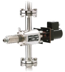
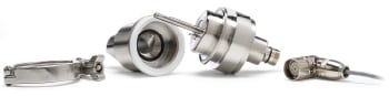
Rotational viscometers (Figure 1) are widely accepted tools for the measurement of viscosity across most industries. The spindle of a rotational viscometer, when inserted into the liquid, rotates at various fixed speeds, thereby shearing the material continuously at defined shear rates. Simultaneously, the viscometer measures the amount of torque resistance experienced by the spindle at each speed of rotation. This torque measurement is quantified as a “shear stress,” which acts across the surface area of the immersed portion of the spindle. These two key concepts — torque resistance and shearing action — are combined in an equation that defines apparent or dynamic viscosity as the ratio of shear stress to shear rate.
The unit of measurement used to quantify rotational viscosity is the centipoise (cP) in the western hemisphere, and the milliPascal second (mPa-s) in other countries, although there is some degree of overlap in useage. The good news is that the two units are interchangeable because 1 cP equals 1 mPa-s. There is a way to correlate viscosity measurements made with dynamic and kinematic methods for materials that are Newtonian, using the following equation: Dynamic viscosity = kinematic viscosity × density (for more on the fundamentals of viscosity, see Viscosity: The Basics, Chem. Eng., August 2009, pp. 34–39).
Process measurements
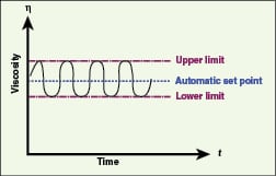
Automatic control of process fluid viscosity ensures consistent product all the time, reduces product hold times, and can eliminate human errors and expensive sample testing (Figures 2 and 3). Also, it provides for a complete record of how the process varied over a span of time, instead of at just one point in time. In a plant environment, there are many ways that viscosity can be measured, such as by a rotational viscometer, a vibrating element and by a falling object. Understanding whether a true, defined shear-rate measurement is needed, or if you are really just looking for set-point control, is beneficial when choosing the right type of instrument for your application.
Process measurements are made inline or in a flow loop. A bench-top rotational viscometer can be used for off-line or near-line measurements, where a sample of the process fluid is drawn and tested under controlled conditions (using the same bath temperature, shear history, shear rate and so on). Inline viscometers are immersed in the process stream and measure continuously under process conditions. Installation can be in a side-stream, in the main flow stream or in a tank. It is important to consider how cleaning and maintenance of these devices might occur, if necessary, when deciding on the installation.
 |
 |
It is also important to make sure that a representative sample of the fluid will be measured. Possible concerns about stratification, mixing and turbulence should be considered. The instrument will measure the product with which it makes contact, so making sure the fluid that the instrument “sees” is the material that you want it to measure, is a primary consideration. The demands of laboratory versus process environments are different, so it is unlikely that the same equipment can be used for both styles of measurement or that the exact same measured value will be generated. However, if done properly, the results of both laboratory and inline measurements will follow the same trend, making inline measurement useful for ensuring consistent production quality.
Choosing an instrument for inline measurement. When evaluating an instrument for inline viscosity control, there are several parameters that must be considered to provide the proper installation. The answers to these questions will eliminate some types of viscometers, and aid in defining the specifications of the final instrument. These questions include the following:
• What are the minimum, maximum and average pressure and temperature requirements for the application?
• What is the expected viscosity range, and control set-points desired?
• What are the minimum, maximum and typical flowrates in the process?
• What is the area electrical classification (NEMA 4; NEMA 7; ATEX, for example)?
• What are the necessary materials of construction, and recommended seal and elastomer materials? (This can often be determined based on what the plant is using for other process equipment in the area, such as pumps.)
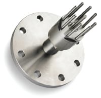
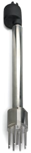
• Where will the instrument be mounted? This will determine the style of instrument to be used. Examples include a tank/flange mount (Figure 4); a flow-through housing (Figure 1); a probe style for barrels (Figure 5); and mounting from the top of an open tank
For process control measurements, the critical factors are stability, repeatability and sensitivity to changes in viscosity. A stable, repeatable reading from an instrument that is sensitive to change in the process will allow the engineer to properly control the process.
 |
Applications
Most products are formulated to flow, spray or coat in a controlled manner. Monitoring viscosity at critical shear points ensures that the product will act the same way every time for the user. This is the most tangible indicator of quality. With the increase in standardization initiatives, such as ISO 9000 and process analytical technology (PAT), there is an increasing use of viscometers to establish and document the desired properties of products. To a much larger extent, the use of viscometers for quality control, and in particular, the use of inline viscometers, wherever possible, to automate the process of controlling desired fluid properties is on the rise. Quality, consistency and customer acceptance require testing and control of key parameters, of which viscosity is certainly an important one.
Some typical operations where process viscosity control can be important include the following:
Determining the endpoint. For applications involving chemical reactions, viscosity of a product is continuously monitored in-tank and the process is either stopped, or the next steps are taken once a specific viscosity limit is reached.
In addition to determining the endpoint of chemical reactions, this approach is also used to determine the endpoint of blending operations, such as the blending of multiple ingredients in a batch process. One example is synthetic-fiber manufacturing. Latex, spandex and other synthetic materials are used to manufacture fibers, which are stretchable, rugged and used in many applications such as clothing. The manufacturing process is carried out in a reactor, where both temperature control and tight viscosity control are required over the steps and additions made during the process.
Carrying properties in oil and gas. In many oil and natural-gas production applications, viscosity is monitored and controlled to make sure that the fluids have the proper rheological properties to carry solids. For example, hydraulic fracturing fluid must have the proper viscosity under various shear conditions to carry the proppant downhole, and deposit it at the required location. For drilling fluids, the viscosity must be correct to carry the cuttings away from the drill bit and out of the hole, as well as to lubricate the bit.
Field engineers in oil-and-gas drilling operations can experience operating problems if the viscosity specifications of fluids pumped downhole are incorrect. This complicates testing procedures, increases the risk of costly errors and wastes time. Consequently, it is necessary to ensure fast, accurate viscosity measurement, data collection and analysis of fluid samples before they are pumped downhole.
The inline couette viscometer (Figure 1) gives field engineers reliable viscosity measurement, onsite at the well. This simplifies complicated test procedures, minimizes human error and ensures quality control without delay. The instrument output allows for constant monitoring and reporting of fluid viscosity or for use in ECD (equivalent circulating density) calculations by oil-rig engineers.
Oil-delivery systems, such as for burners. In this application, the viscosity of a fluid is controlled so that when it is pumped through a spray nozzle, proper atomization of the material occurs. Proper atomization through spray nozzles, which requires continuous and accurate viscosity measurement and control, ensures the best combustion efficiency in oil-delivery systems. To burn fuel oil at the high-volume flowrates demanded of modern boiler units, the oil must be atomized (dispersed into the furnace as a fine mist). This assures high-speed vaporization and ignition. Most burners atomize oil by shearing the oil into small droplets. Burner manufacturers recommend that the oil be supplied to the burners at a specific viscosity to maintain consistent atomization. Failure to maintain proper atomization results in the following: poor fuel burning due to carbon and soot buildup; higher fuel consumption and costs; increased stack emissions and possible fines from government agencies.
The inline process viscometer monitors and controls viscosity and temperature in pressurized oil-delivery systems. Repeatable viscosity measurements are necessary to maximize the efficient atomization and delivery of a variety of paraffin-based oils, asphaltic-based oils, as well as heating fuels and waste oils. The process viscometer can include additional design considerations, which may also be of interest to other spray-type applications, such as spray-drying operations. Some of these considerations are the following:
• Bypass loop for viscometer installation for fail-safe operation
• Use of viscosity feedback to control the heat rate to the oil-feedline heat exchanger
• Output from the viscometer may go to a single-loop controller that instantly responds to inline viscosity changes
Quality control.To ensure consistent quality of many different products, it is important that the viscosity be constantly measured and controlled during the production process. Inline measurement ensures consistent quality control in realtime. It saves on laboratory testing times, and reduces hold-up of product in tanks waiting for evaluation. Examples of quality-control and quality-assurance applications include shampoos, detergents and yogurts to name a few. In these cases, too thin a product might appear to be of poor quality (such as a runny yogurt, or a shampoo that pours like water, without any body). Here it is a matter of consumer perception where specifications of final products are written by companies based upon consumer test groups, and the product must fall within these specifications in order to be shipped.
Other quality-related applications where viscosity is important are in coatings, such as paint applications. A few more examples follow.
Roll-coating thickness control.When dealing in any large-volume coating and printing applications where millions of products are being printed per day, the payback on the cost of inline control can be very short when measured against costs of wasted ink, varnishes, or coatings from too high a viscosity or from wasted product if the viscosity (and hence the color) are too light.
In printing applications, constant maintenance of proper ink viscosity ensures the quality of the printing, which reduces rejects and waste, while also keeping ink costs to a minimum. To assure the uniform application of inks on a variety of substrates (boxes, newspapers, cartons) it is necessary to control viscosity. Continuous monitoring and control of the ink reservoir viscosity using an inline viscometer (Figure 6) can provide viscosity measurement and control at multiple stations and save money by using less ink. Similar controls are needed in the coating of, and the printing on soda and other beverage cans.
Dip-coating thickness control. The thickness or consistency of a fluid is controlled to provide a dependable and uniformly coated item when dipped, then removed, from a coating tank. In this application, the thickness or consistency of a fluid is controlled so that when something is dipped in it and pulled out, it is uniformly and consistently coated.
Dipping applications are designed in automated systems whereby an item is brought over a tank or pan, dipped into the bath, removed and allowed to drip dry before proceeding through the process. The main problem with the open tank or pan is with the evaporation of fluids to the environment. Viscosity control is used for addition of water, solvents or other modifiers as needed to control viscosity to a set point. In pharmaceutical capsule manufacturing, for example, if the fluid is too thin, the capsule will break during filling, or dissolve too soon when swallowed, which would release medicine in the throat instead of the stomach. If it is too thick, then there is raw material waste on millions of capsules that will raise product costs, and it may not dissolve properly when swallowed.
For food batter applications, too thin a batter will mean improper coating and product quality. Too thick a batter will mean bad product quality, longer cook and dry times, and raw material waste. You can easily imagine a chicken nugget with too much batter. This can be from too viscous a batter during the coating process.
Edited by Dorothy Lozowski
Author

Steve Cicchese is the general manager of process sales and marketing for Brookfield Engineering Laboratories (11 Commerce Blvd., Middleboro, MA, 02346; Email: s_cicchese@brookfieldengi neering.com; Phone: 508-946-6200) where he has worked for the past 12 years. Prior to that, he spent 15 years with Bird/Baker Process, a manufacturer of liquid-solid separation equipment. Cicchese holds a B.S.Ch.E. from Northeastern University, an MBA from Babson College and a certificate in business administration from Harvard University. He is a member of the AIChE and Society of Petroleum Engineers, and has written numerous articles on process viscosity measurement in various industries, including food, printing, asphalt and oil and gas.