![]()
Modern temperature instrumentation simplifies technician access, calibration, and SIL procedures.
By Keith Riley, Endress+Hauser
As temperature instrument technology has matured, there is less focus on the actual measured value and more on added value. Accuracy and stability are considered basic thresholds, and what process owners really want to know is how a temperature instrument can further improve the overall process.
For most process owners, added value falls into one of three basic categories:
- With plants faced with continued attrition of onsite maintenance and service support, can the instrument assist with simplifying tasks such as installation, commissioning, calibration, and troubleshooting?
- Safety and Risk Reduction. Will the instrument reduce the risk to personnel, property, or the process?
- Productivity and Profitability. How can the instrument improve process efficiency, reduce labor cost, and increase profitability?
Temperature, as arguably the technology with the most measurement points in most process plants and facilities, presents a huge benefit potential in all three categories.
Simple Access
The most time-consuming activities associated with any temperature instrument are commissioning, calibration, and service. Technicians on the plant floor need to access data in the instrument, such as status, diagnostic messages, etc., to perform these services.
Most temperature instruments support a standard 4-20 mA HART communication protocol. While robust and well accepted, this two-way form of communication also requires specialized tools such as a HART modem, software, and the correct device type manager (DTM) and device driver (DD), depending upon the interface device employed. Essentially, the technician goes to the instrument, plugs in the interface device, and performs the required maintenance tasks.
The advent of wireless access to temperature transmitters changes all this. Many instrument vendors now offer Wi-Fi, WirelessHART, and Bluetooth connections to temperature transmitters.
For example, all a technician needs to interface with a Bluetooth-capable instrument is a smart device—such as a handheld computer, smartphone, or tablet—and the corresponding app. The technician can securely communicate with the device from distances up to 40 feet away (Figure 1). Not only can a technician see the output of the device, he or she can also perform all the same commissioning and diagnostic functions normally associated with a HART modem and DTM.

Figure 1: With Bluetooth, a technician can access a temperature instrument from up to 40 feet away using an Endress+Hauser Field Xpert SMT70 handheld tablet PC tool.
The ability to access a temperature instrument from a distance means the technician doesn’t need to climb scaffolding or ladders to reach instruments installed on tops of tanks or in otherwise inaccessible locations. This increases technician safety and reduces the amount of time needed to perform maintenance tasks.
Calibration and Diagnostics
In certain critical temperature measurements, calibration of a temperature instrument can be required every 6 to 12 months. Calibration is necessary to detect measurement drift, and permit adjustment or replacement of the instrument.
The exact timing of calibrations is determined via a risk/cost analysis. A more frequent calibration cycle reduces risk to the facility, but conversely increases cost.
Some RTDs (Figure 2) automatically perform an in-situ calibration once a predetermined set of conditions are met. This occurs with no interruption in the process or measurement signal. The two conditions currently required are a process temperature that has met or exceeded 253°F (123°C) followed by a controlled cooling cycle to below 244°F (118°C). This most commonly occurs during a steam-in-place sterilization or some other type of aseptic process.
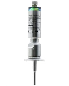
Figure 2: The Endress+Hauser TrustSens RTD can calibrate itself when certain process conditions are met.
Once these conditions are met, the RTD’s integrated transmitter will automatically compare the measured value against an embedded traceable reference. Any deviation is identified, and if it exceeds the customer specified tolerance, notification occurs. The safety or metrology department can then determine if adjustment or replacement of the existing RTD is needed.
This in-situ calibration eliminates the need to periodically remove the instrument’s sensor from the process, take it to a calibration lab, and reinstall it—thus saving time and money. Due to the popularity of this feature, instrument vendors are looking to develop additional temperature thresholds.
Temperature sensors and transmitters are also becoming available with advanced diagnostics to simplify the job of maintenance technicians. Endress+Hauser’s TMT82 temperature transmitter (Figure 3), for example, has a two-channel function that detects drift between sensor 1 and sensor 2, detects a broken sensor, detects corrosion on the sensors, and provides automatic sensor backup if one sensor fails.
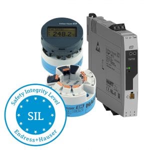
Figure 3: The Endress+Hauser iTEMP TMT82 temperature transmitter has built-in diagnostics and is factory programmed to facilitate SIL testing.
When the TMT82 detects a problem, it sends a standard NAMUR NE017 diagnostic message to the control system via its 4-20 mA HART, Profibus or Foundation Fieldbus interface. When the maintenance technician accesses the TMT82 from a smartphone or computer, all diagnostic messages and data are available.
Safety and Risk Reduction
Temperature is a critical measurement in a safety instrumented system (SIS). As parity among instrument vendors regarding safety integrity level (SIL) certification has been achieved, the more significant risk is human error associated with commissioning and proof testing.
The typical commissioning of a SIL-rated device in a SIS involves setting the SIL relevant parameters (SRPs) in conjunction with an instrument specific SIL checklist developed by the safety engineer. Since a technician may need to enter six to eight values, there is ample opportunity for errors due to inexperience or interruptions. Similarly, during proof testing, the correct instrument-specific SIL checklist must be located, and then each of the SRPs must be confirmed.
New SIL-capable temperature transmitters have eliminated much of the risk inherent with this process. Transmitters designated as SIL-capable—such as the Endress+Hauser TMT162 (Figure 4)—are factory programmed with SRPs. While field customization is still possible, the amount of human interaction and setting adjustments is minimized.
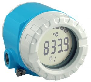
Figure 4: The Endress+Hauser TMT 162 temperature transmitter is SIL-capable.
These same transmitters can produce and store the SIL checklist. Upgraded DTMs permit the Safety Engineer to access this information directly from the transmitter and print a PDF on demand, reducing lost or duplicated paperwork.
Checksum is a unique numeric code generated by the transmitter based upon which SRPs are used. During a proof test cycle, a manual review of the six to eight SRPs is required. But a simple comparison of the current Checksum value currently stored in the instrument against the last stored SIL checklist will confirm if any SRPs have been altered. If the Checksum numbers match, no changes have occurred and the technician can safely and efficiently proceed with the balance of the proof test. A 96% proof test coverage can typically be performed in approximately 10 minutes with a SIL-capable instrument, compared to 20-30 minutes for instruments without this capability. It will vary depending the experience and efficiency of the technician.
Productivity and Profitability
As noted above, temperature instruments need to be calibrated, which can be a time-consuming procedure that might require the process to be shut down, thus adversely affecting productivity. In most cases calibration requires the following sequence:
- Disconnect the loop wiring
- Remove the sensor/transmitter
- Transport the sensor to a calibration lab
- Reconnect loop wiring in the calibration lab
- Insert the sensor into the reference for calibration
- Reverse the steps to place the sensor/transmitter back in service.
Typically, this process will take a minimum of 30 minutes per instrument and adds additional risk to the process, including damage to wiring from connecting and disconnecting the leads, possible damage to the RTD or thermocouple (T/C) sensor when it’s transported to and from a calibration lab, and the possibility of miswiring the leads during reconnection.
A quick disconnect feature (Figure 5) can reduce calibration and downtime by two-thirds while reducing risk by eliminating the need to remove leads from the transmitter. This also makes it much more practical to perform calibration at the measurement point using a mobile reference.
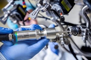
Figure 5: The Endress+Hauser QuickNeck allows an RTD sensor to be removed quickly with disconnecting wires.
The time saved with easier instrument access—i.e., no scaffolding or ladders involved in reaching instrumentation—combined with time savings from self-calibrating sensors, SIL-capable transmitters, and quick-disconnect sensors can add up to considerable labor savings. In a plant with 1,000 or more temperature instruments, the labor savings can amount to several hundred thousand dollars per year, with additional savings achieved by reducing risk and increasing uptime.
Achieving Savings
While it seems a monumental task to upgrade a plant with 1,000 or more temperature instruments, such a project may not be as big as it appears, thanks to several factors.
- Any temperature instruments that have been replaced in the past few years may already have some or all of the necessary technical capabilities built in. Just because a plant isn’t using all the advantages of a SIL-capable instrument or Bluetooth communications doesn’t mean the features aren’t there.
- Instrument vendors have been preparing for remote access for quite a while. One of the biggest steps has been installing bar codes, QR codes, RFID labels, or other identification on instruments so a technician can identify them remotely.
- Instrument vendors have been aware of commissioning, calibration, and SIL testing problems for years, and have been developing devices, software, and technology to deal with these and other issues.
- All the data needed to integrate a temperature instrument into a new commissioning and calibration program—such as DDs, DTMs, SRPs, etc.—should be available on each instrument vendor’s website.
- Even if a plant has temperature instruments from multiple vendors, this doesn’t pose a problem for modern software tools. For example, the Endress+Hauser Field Xpert tablet PC tool (see Figure 1) has more than 2,700 pre-installed device and communication drivers, allowing it to work with many different instruments from a wide variety of vendors. In addition to this software protocol support, connectivity options include USB, Ethernet, HDMI, Wi-Fi, and Bluetooth, allowing local or remote connection to most instruments.
The best way to determine the next steps in an upgrade project is performing a plant-wide installed base analysis of temperature instruments to identify what’s currently installed, check to see if the installed instruments have the appropriate technology, and determine what needs to be done. Any major instrument vendor can assist with this type of project.