A plant turnaround is always challenging in the chemical process industries (CPI). But with proper planning and reliable procedures in place, last-minute time crunches and failures can be prevented. When haste combines with faulty methods, costly problems result.
This article presents three examples of actual plant turnarounds and the lessons that can be learned from them.
Case study No. 1: Sour-water stripper
A sour water stripper (SWS) is a relatively small unit that treats wastewater from other process units of the plant, in this case a petroleum refinery. After treatment, the wastewater is directed to the sewage system, wastewater plant and ultimately to a nearby river.
The plant
This particular plant has no spare SWS unit, so in case of failure, the entire refinery must be shut down because untreated water is prohibited from being discharged into the river.
A sour-water storage tank may be used in an emergency with a capacity for five days of normal wastewater accumulation. In the event that the SWS is down, it must be repaired and started within the five days, otherwise the entire refinery must be shut down as mentioned before.
In this instance, the SWS column was packed with metal random packing. Column performance was steeply decreasing, because of packing fouling. The column had to be cleaned immediately, before the contaminants concentration in the treated water reached an unacceptable limit. A five-day turnaround was planned, which was long enough to shut-down the SWS, unload the metal rings, clean the rings and repack the column, and finally to restart the SWS unit. All refinery units were running at minimum capacity, directing all sour water to the five-day storage tank. Under normal circumstances, this should be a routine cleaning operation.
Fire
It is well known that pyrophoric iron is formed or accumulated in SWS units [1]. When the unit is put out of operation, the standard safety precaution is continuous washing with water to keep all internals wet and prevent pyrophoric iron from self-ignition and subsequent column fire. In this particular unit, operators had never run across pyrophoric iron before. Therefore (and due to the winter conditions), this “wet procedure” was not applied. The SWS column was not continuously washed with water, but opened after steam-out under dry conditions. This short-cut caused a dangerous situation with serious plant operational consequences.
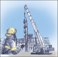
As one might expect, when air entered the hot column, pyrophoric iron self-ignited, resulting in a column fire. Although the manholes were closed immediately and nitrogen was fed into the column, the fire inside continued. Temperatures inside the column reached 2,000°F; the column shell became warped and bent, and the tower internals were found melted into stainless-steel icicles. The fire was extinguished at the last moment before total shell failure. Fortunately, the column did not fall onto the nearby pipe-rack, but it had to be secured with a mobile crane to prevent its fall (Figure 1).
Problem
Having no spare SWS unit, the five-day sour-water-storage tank slowly filled with water. Only five days were left to fix the problem or find another solution, after which the refinery would have to be shut down. Plant shutdown in winter time was a nightmare for plant management due to the extreme time and cost involved.
The fire occurred at 8:00 a.m. By 10:00 a.m., it became clear that the column could not be used anymore and had to be replaced or at least shop-repaired. But there was no chance to make repairs within the five days — repairing the shell in the shop and acquiring replacements for the damaged internals were estimated to require a minimum of two weeks. General frustration ensued and an emergency team was set up for express column-shell repair. By noon, it became clear to the troubleshooters that another column was needed to process sour water.
How to make a spare SWS
A sour-water stripper looks like a simple, “easy to find a replacement” distillation column. However, this is not true. Although the SWS is not a big complex column, it is very specific in metallurgy and auxiliary equipment. A suitable spare column must have a sufficient capacity, appropriate design pressure and the correct material of construction (as well as its reboiler, condenser, reflux drum and reflux pump). Perhaps more important is the offgas route from the SWS.
In this case, the offgas from the SWS is routed to a sulfur recovery unit (SRU), so the spare SWS must be connected to the SRU as well. Considering all the factors, the SWS is quite a unique unit. There was only one potential candidate for a spare SWS meeting all requirements — the amine unit regenerator.
Coincidentally, there was one idle amine regenerator at a nearby hydrotreater unit that was recently set on hot circulation to reduce sour water production.
Two teams had been working in parallel — one team for the SWS column repair and internals supply, and another team for the spare SWS design. The author was a member of both teams. The following steps were subsequently taken:
1. At 2:00 p.m. the amine unit regenerator was checked for sufficient capacity.
2. By the end of the day, the temporary cross-connection piping was specified.
3. Within the next two days, the temporary lines were designed, assembled, and pressure tested.
4. The amine-regenerator control screens in the distributed control system (DCS) were reprogrammed for new operating conditions.
A happy ending
The spare SWS was successfully started ten hours before the sour water tanks filled up. A plant shut-down was avoided.
There was enough time to make a thorough shop-repair of the damaged SWS column. The warped SWS column was cut into three pieces. The damaged part was replaced with a new cylindrical section. New internals were designed, manufactured and delivered on an emergency schedule within eight days. The SWS unit was successfully put back into operation after a two-week repair period.
Lessons learned
1. SWS units are prone to fouling and pyrophoric formation. Special precautions shall be applied for SWS cleaning.
2. Trays should be preferred to packing for SWS service, because trays are easier to clean and less prone to metal fire.
3. The standard five-days capacity of a sour-water storage tank might not be sufficient in the case of serious trouble — a spare plan should be prepared to avoid costly plant shutdown.
Case Study No.2: LPG debutanizer
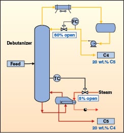 |
A petroleum refinery was completely shut down for planned maintenance and cleaning. However, the turnaround was not well managed, causing the employees to rush their work and not follow some procedures properly. As a result, after startup, a liquefied petroleum gas (LPG) debutanizer (Figure 2) did not meet the same product quality that was regularly met before the turnaround. Both top and bottom products were off specification and the column did not provide any fractionation despite operators maintaining the same reflux rate as before the turnaround.
Problem analysis
Insufficient product separation had been first diagnosed as being caused by extremely low tray efficiency. It was suspected that the maintenance crew left open manways in the column trays. Later, a close look at operating conditions showed that the column was well refluxed, but the reboiler duty did not match. The reflux rate had been the same as before the turnaround, but the steam rate to the reboiler was close to nothing (Table 1).
| Table 1. LPG debutanizer performance before and after turnaround |
||
| Before turnaround | After turnaround | |
| C4 purity | 0.5 wt.% C5 | 20 wt.% C5 |
| C5 purity | 1 wt.% C4 | 20 wt.% C4 |
| Reflux | valve 60% open | valve 60% open |
| Steam to reboiler | valve 50% open | valve 5% open |
The debutanizer column virtually violated an enthalpy balance. Instrument readings and control valve positions had been verified in the field, and it was concluded that both flowrate readings were correct. Distillation columns can’t run without any reboiling, but this mysterious debutanizer did.
The explanation of the mysterious behavior was elementary — reflux liquid was not coming down through the column, but instead, it had been entrained back to the reflux receiver and re-circulated.
Finding the root cause
Heavy liquid entrainment is usually addressed as jet-flood, caused by extreme vapor load. In this case, the vapor rate could not cause any entrainment because the reboiler duty was almost none. One suspicion was that one of the tray downcomers was blocked with a piece of mineral wool insulation or other debris.
Plant management was not very pleased with this explanation, commenting that “The column has been just cleaned and inspected as being in perfect operating condition, but you claim the major malfunction is caused by some debris? Should the LPG plant be shut down again for an inspection and cleaning that was just performed?” Management needed a justification due to the expense involved with another shutdown. The troubleshooter proved that the problem was real and it could not be fixed without a unit shutdown.
The short-term shutdown of the LPG unit was carried out, keeping the rest of the refinery running at a low capacity and temporarily flaring LPG as there was no spare LPG plant. The debutanizer column was open, after water washing and air purging. The inspector’s first reaction was surprise. Everything seemed fine and the column seemed clean.
Mystery solved
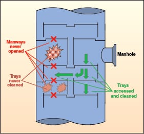
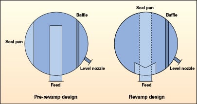
The debutanizer column was equipped with two-pass trays, with side and central downcomers. On every other tray, the central downcomer forms a wall in the column center, effectively blocking access from one side of the tray deck to the other. It is for this reason that two-pass trays should have two manways — one for each segment — to ensure access to both column sections.
 |
 |
In the case of this particular LPG debutanizer, the trays were of an old design, with separate I-beam support and bolted decks. The maintenance crew “did not waste time with opening both manways because trays had been always clean in the past.” Only one manway had been opened in every tray for inspection and cleaning. On trays with central downcomers, only one half of each tray had been cleaned as a consequence. This incorrect cleaning procedure has been applied for 20 years, since the column first started up. The sections “behind downcomer” had never been inspected or cleaned. When both manways were opened, every other tray was found to be covered with a 1-in. layer of rust and dirt. Valves were stuck and some downcomers were blocked. In the past, cleaning was performed by flushing with water, so washed out dirt settled in the non-accessed tray sections until they became completely blocked (Figure 3).
Lessons learned
1. Cleaning and inspection procedures shall not be compromised, despite turnaround time constraints.
2. “Sweeping dirt under the rug” is not the proper cleaning procedure.
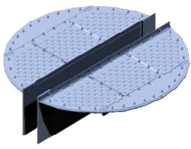
3. If the trays were of modern design, with fast opening manways and locks (Figure 4), the maintenance crew would not have compromised the inspection and the cleaning procedure.
Case Study No. 3: Wrong level indication
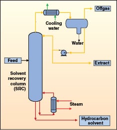 |
A solvent-recovery column at a petrochemical plant (Figure 5) was revamped, converting the existing one-pass trays to two-pass, high-performance trays to account for a large capacity increase and much higher liquid flowrates. After startup of the unit, an unstable reflux-drum level was observed making control of the column difficult.
The diagnosis by plant personnel was that the unstable reflux-drum level was due to flooding of the tower and entrainment carryover. The immediate solution proposed by plant personnel was to revamp the tower to change from trays to packing.
Trays versus packing
The immediate reasoning for selecting packing was that a packing could be chosen that would appear to have more capacity than the high-capacity trays currently in the tower, and that the nominal HETP (height equivalent per theoretical plate) reported by vendors would be more than enough to achieve the number of theoretical stages required. The calculated flood fraction of high-performance trays is 79%, whereas the calculated flood fraction of 125 m2/m3 X-type structured packing is 70%.
The nominal packing HETP for this type of packing was reported as 1.2 m. This appeared to meet the separation requirements, as modeling had shown the revamped trays were generating five theoretical plates at 610-mm tray spacing. The height available in the tower appeared more than enough to achieve the separation with the benefit of a lowered flood value.
It was at this point that fractionation specialists were called in and the dangers of applying a nominal HETP to different applications were noted. In this case of solvent separation, where polar components are involved, extrapolating HETPs used for low relative volatility non-polar hydrocarbons should not be considered. By cross-consulting an operating data bank, it can be seen that for moderate pressure applications, a structured packing surface area of 200–250 m2/m3 would be required to achieve the same or better efficiency than the trays, regardless of reported nominal values.
At the specific liquid flux evaluated at these conditions, the capacity of even a high-capacity structured packing at this specific surface area would be much less than the high-performance trays currently installed in the tower. Finally, the revamp scope and downtime required to complete a revamp from the tray-to-packing solution would be costly.
Root cause evaluation
Examining the design of the trays themselves resulted in no immediate cause for concern, and indeed rating methods resulted in a predicted flood value of 79%. Entrainment and flooding were not expected at these conditions.
An examination of the raw data and the actual symptoms would need to be conducted. The main operating issues came about as extremely unstable overhead level and the inability to control the overhead pressure. As the overhead pressure increased, the operators reacted by reducing steam to the tower bottoms or decreasing reflux to the tower. The overhead reflux-drum level would dramatically rise to high levels and the control system began hunting for the proper level. If overhead pressure decreased below the set point, the reflux was increased or steam was increased. Overall it was difficult to reach a steady-state operating point.
The unstable operation was assumed to be caused by flooding in the tower. When evaluating the tower for other flooding signs (such as higher pressure drop), it was found that no flooding symptoms where observed. The bigger problem was to diagnose what the root cause was, and to find the symptom of the root cause. This would only be found after examining the tower under more stable conditions.
Reduced feed charge operation
At a feed charge-rate of 50% of the revamp conditions, a clearer picture was observed. At these conditions, it was noticed that the bottom level instability preceded the overhead reflux instability. In this case, the bottom level would rise resulting in increased steam or decreased reflux, which would cause instability in the overhead level. The bottom level would dramatically fall as it reacted to the step changes. At these conditions, the overhead pressure was relatively stable.
Field observation
Incorrect field measurements — level measurements in particular — are not uncommon issues faced by troubleshooters. The best way to confirm that these issues are real is to actually walk to the unit and look (visual check). In this case, the problem became immediately obvious when liquid was observed to be draining into the top level nozzle at the bottom of the column.
Tower internals/control nozzles
 |
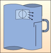
In general, designers of tower internals should evaluate the new internals of a tower for the arrangement relative to the process control nozzles. In the case of simple revamps where the number of passes remain the same, this is relatively trivial. In the case where the tower is being converted from trays to packing, or in the case where the number of passes changes, some extra care should be considered. In this particular case, the internal-equipment designer was provided with information to evaluate all process and control nozzles that were located inside the new trays; however, no information was shown for the bottom level nozzles relative to the reboiler return. Figure 6 compares the prior revamp bottoms arrangement to the new arrangement.
The revised arrangement directed the two-phase reboiler return directly into the top level nozzle (Figure 7), which resulted in liquid draining into the level. However, this arrangement resulted in control issues. A seemingly high level in the product draw saw operation increase the reboiler steam, which in turn would follow with a rise in reflux flow.
Modifications
 |
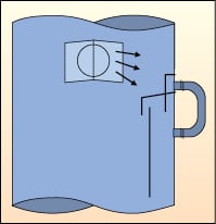 |
Adding new level taps at an elevation below the top of the reboiler baffle arrangement was probably the most straightforward option. However, adding new nozzles may require PWHT (post weld heat treatment) or at least additional approval and time. In order to further minimize the downtime, a simple solution was used: installing a half pipe to seal off the top level nozzle from the reboiler return. This half pipe was simply extended through the baffle, as shown in Figure 8. The result was much more stable tower operation at the full range of feed rates.
Lessons learned
1. An evaluation of tower-internals selection with regard to process nozzles should be considered not only for mechanical interference, but also in regards to a detailed analysis of fluid flow and process control. An extra review step with all parties involved can further eliminate future issues.
2. Careful troubleshooting and diagnosis by specialists in the particular engineering discipline is a key to correct diagnosis and preventing further costly revamps that do not address the root cause.
References
1.. Mary Kay O’Connor Process Safety Center, “Best Practices in Prevention and Suppression of Metal Packing Fires,” Texas 2003.
Endnote
The contents of this article was first presented at the 2013 Spring Meeting and 9th Global Congress on Process Safety of the American Institute of Chemical Engineers (San Antonio, Tex.; April 28 – May 2, 2013).
Authors

Petr Lenfeld is senior process engineer at GTC Technology Europe s.r.o. (Prikop 6, 60200 Brno, Czech Republic; Phone: +420-511-118-005; Fax: +420-545-174-601; Email: plenfeld@gtctech.com), and specializes in process design and troubleshooting. He holds a Ph.D. degree in chemical engineering from the Institute of Chemical Technology, Prague, Czech Republic.

Ian Buttridge is the technical director for GTC Technology Inc. (1400 WestPark Way, Building 100, Euless, TX 76040; Phone: +1-817-685-9125; Fax: +1-817-685-0236; Email: ibuttridge@gtctech.com) and specializes in fractionation applications and equipment design. He holds a B.S.Ch.E. from Texas A&M University.