Under the right conditions, the smallest atom can attack and disable sophisticated instrumentation. Understanding how this happens can help users avoid problems
Engineers of a certain age may remember the childhood disappointment of a helium-filled balloon going flat overnight. This experience illustrates how small atoms, such as helium, can diffuse through materials, even those that seem impermeable, such as the walls of a latex balloon. The lesson learned may come back to mind when trying to diagnose the failure of a pressure instrument installed in an application involving hydrogen.
Few engineers would consider a vessel constructed of 316 stainless steel or Alloy C to be permeable, but there are situations where austenitic stainless steels and high-nickel alloys can exhibit the same porosity as a balloon due to their grain structure. To be clear, a stainless-steel tank isn’t likely to start leaking spontaneously, but permeability can become an issue under specific conditions with specific types of instrumentation. This article discusses how permeability happens in general terms, and then in the context of a specific process application.
Working with the smallest atom
With an atomic number of one, hydrogen is the smallest and lightest atom, composed of one proton and one electron. In its natural state, hydrogen exists as a diatomic molecule, H2, which is a gas at ambient conditions. The H–H bond is very strong, but under the right circumstances, gaseous H2 can dissociate, just as a water molecule can dissociate into two ions, OH– and H+. An H+ ion (a cation) is nothing more than a single proton, and it can penetrate through microscopic voids in a thin metal barrier, such as the diaphragm of a pressure instrument (Figure 1). The degree of porosity in the diaphragm metal is influenced by how the metal was formed and welded.
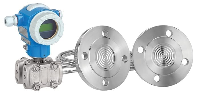
Figure 1. Using a remote diaphragm and fill fluid allows a pressure instrument to be mounted away from a process, avoiding the problems normally associated with conventional impulse lines
Once the H+ ions have migrated through the diaphragm, they move into the fill fluid where they capture electrons. These reconstructed atoms now recombine to form H2 molecules and remain permanently trapped and dissolved in the fill fluid, unable to pass back through the diaphragm as molecular hydrogen. As long as there is sufficient positive pressure on the diaphragm, the hydrogen remains dissolved and there is no problem.
However, if the pressure falls to atmospheric or below, the H2 can come out of solution and form bubbles in the fill fluid, like CO2 from carbonated water. This raises the internal pressure behind the diaphragm, which is the weakest point of the containment housing, deforming the diaphragm and causing it to bulge out like a can of spoiled fish, exhibiting the “jiffy-pop” effect (Figure 2).
The more technical description is catastrophic membrane deformation, which requires replacement of the complete transmitter.
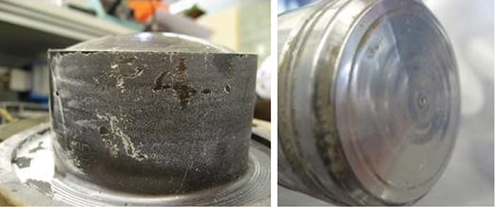
Figure 2. Once hydrogen permeates the diaphragm, it becomes trapped in the fill fluid, gradually building up pressure until it distorts the diaphragm, as shown in these two pictures
Aqueous applications
A common situation where this happens involves water, a product normally considered benign. The driving force causing ions to migrate from water through a diaphragm is independent of pressure. The action is galvanic, which causes this problem to appear in some unexpected applications, such as wastewater- or biogas-treatment plants.
Picture this situation: a plant’s maintenance department installs an access ladder into a large sump pit where a pressure instrument is installed nearby to measure level. The frugal engineer chooses a hot-zinc galvanized ladder rather than stainless steel, hoping to minimize corrosion while saving a few dollars.
After operating for two months, the sump is drained for cleaning and the stainless-steel instrument diaphragm distends due to hydrogen permeation. This negates the cost saving on the ladder, so the maintenance manager wants to know why it happened. After all, it’s just water. This isn’t a hydrogen application, is it?
It became a problem due to galvanic interaction, or “battery effect,” between the components. The zinc on the ladder acts as the anode and the stainless-steel diaphragm of the pressure instrument is the cathode. The water present in the tank is electrolyte.
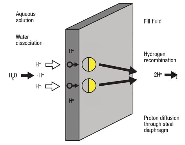
Figure 3. In aqueous solutions, galvanic action can cause water molecules to dissociate and diffuse through the diaphragm
The result of this galvanic process is a reduction of water molecules into ions at the cathode (Figure 3). Stripped of their electrons and driven by galvanic action, extremely small H+ cations can diffuse through a 316 stainless-steel or Alloy C diaphragm. As described earlier, once on the other side of the diaphragm, the H+ ions capture electrons and recombine into H2 molecules in the fill fluid. This type of diffusion is independent of process pressure, but the diffusion rate can increase with higher temperature.
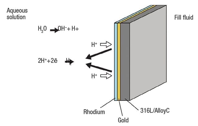
Figure 4. Adding a double coating of gold and rhodium reduces permeability and promotes reformation of molecular hydrogen
The solution for this type of situation calls for a two-layer coating to effectively seal the diaphragm (Figure 4).
First a layer of gold (Au), between 15 and 25µm, is added to the full diaphragm surface. Gold has a very low diffusion coefficient, increasing the hydrogen permeability resistance up to one million times. This is supplemented by an additional coating of rhodium (Rh) on top of the gold. Rhodium promotes recombination of H2 in the solution, reducing its ability to diffuse. With fewer cations present in the solution, plus a far less permeable diaphragm, the problem can be largely eliminated in most situations.
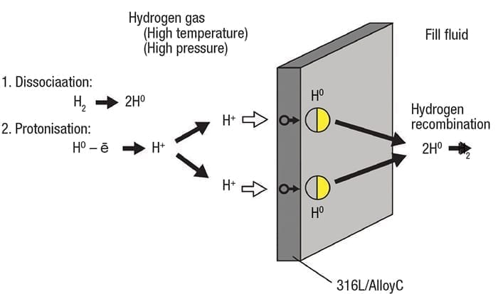
Figure 5. Molecular hydrogen can disassociate and form H+ ions , which are capable of permeating a diaphragm
Gaseous applications
The discussion so far has focused on aqueous solutions with dissociating water molecules, but diaphragm permeation can also take place with gaseous hydrogen where no liquid is involved, although the drivers are different.
Gaseous molecular hydrogen can dissociate into single atoms, and even H+ ions in situations when the pressure and temperature are high enough (Figure 5). Ions deposit on the pressure instrument diaphragm and can be forced through into the fill fluid, where they pick up electrons and recombine into molecular hydrogen, just like in aqueous applications.
The precise points where temperature and pressure become a factor are difficult to define specifically, however, when both variables increase together, the effect is compounded, increasing the rate of permeation.
The solution is different, however, than aqueous applications and calls for a single coating of gold on the diaphragm, without the rhodium over-coat (Figure 6).
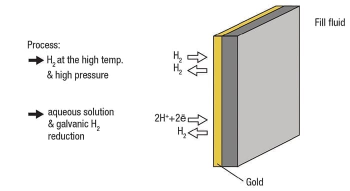
Figure 6. A coating of gold on the diaphragm reduces permeability for both gaseous and aqueous applications. Increasing the coating thickness increases the effective temperature range
The rhodium only performs its function in an aqueous environment, so it serves no purpose here. A gold coating of 15 to 25µm increases permeability resistance by up to one million times, reducing the potential for instrument failure. Increasing coating thickness increases resistance, so a heavier coat extends the operating temperature range. For example, a 15-µm coating is rated for 180°C (356°F), while a 40-µm coating is good to 250°C (482°F).
How much protection is enough?
Adding a layer of gold to a stainless-steel or high-nickel-alloy diaphragm does indeed reduce permeability by a very high degree, but it does not eliminate it entirely. A pressure instrument diaphragm must be thin to be effective, so there is always some vulnerability. The problem is made worse by the fill fluid because the medium is able to capture hydrogen ions and allow them to re-associate in the confined space. The better solution is to use a different pressure-measuring approach that is able to eliminate both problem areas.
Better diaphragm material. The first step is to eliminate the metallic diaphragm, replacing it with a material capable of zero or at least much lower permeability, and not able to participate in galvanic reactions. This suggests something non-metallic, but the material must also be capable of handling high pressures and temperatures. One answer is a ceramic diaphragm, which is impervious to direct hydrogen diffusion and is non-conductive. This way, no metallic component needs to be exposed directly to the process liquid or gas.
No fill fluid. Using a ceramic diaphragm eliminates the need for fill fluid, so there is no medium capable of capturing and accumulating H+ ions. How does this approach work?
Ceramic diaphragm. The ceramic diaphragm exposed to the process is the measurement point. This is possible using capacitance technology in a “dry cell” configuration (Figure 7). The back side of the diaphragm has a metal coating, capable of moving with the diaphragm as it flexes in response to pressure. The coating forms one electrode of the sensor, and a spacer around the perimeter holds it away from the cell’s back side and maintains a desired separation.
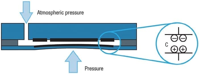
Figure 7. Using a ceramic diaphragm in a dry cell assembly does not allow any internal pressure to accumulate, thereby protecting the instrument
The back side has two electrodes, one in the center and one around the outside. The outer electrode serves as a reference and the center provides a variable signal used to measure pressure. This assembly is sealed to maintain process containment. When used in a gage pressure measurement setup, the interior space is vented to atmosphere through the instrument housing.
As the diaphragm flexes due to pressure, the distance between the electrodes changes and the capacitance value changes with it. This provides the raw analog signal processed by the instrument’s transmitter. This configuration is especially well-suited to hydrogen service because neither molecular hydrogen nor H+ ions can diffuse directly through the ceramic material. Even if hydrogen manages to penetrate the assembly seal at the edge, it will have no effect. There is no fill fluid and the interior space is vented, so such trace amounts simply escape through the instrument.
A ceramic diaphragm is significantly more durable than stainless steel or high-nickel alloys, even when they are coated with gold. It also provides wide temperature and pressure capabilities, assuring a long service life with full integrity.
Example: Ultra-pure polysilicon
Hydrogen gas is used in many processes, both as a component to facilitate a specific reaction or as the end product — for example, as a component in ammonia used for fertilizer production, a fuel source, or a reformer byproduct in hydrotreating and hydrocracking processes. One lesser known, but highly important, use of hydrogen is in the production of ultra-pure polysilicon.
The polysilicon wafers used to form the base for computer chips, photovoltaic cells and various other electronic devices have to be manufactured with a degree of purity that is unimaginable in most industries. Polysilicon for photovoltaic cells must approach 99.999999% purity, achieved through a complex and very hot process. Polysilicon for computer chips must be even purer.
The process begins by turning sand and coal into metallurgical silicon (99% pure) in an arc furnace. Crushed metallurgical silicon is then fed into a fluidized-bed reactor to mix with hydrogen chloride gas at 300°C (572°F). This creates a mix of compounds, including trichlorosilane (HSiCl3) as the primary product. The mixture can be separated using multiple distillation steps, isolating trichlorosilane from the byproducts and purifying it.
All the byproducts and contaminants must be removed for the next step of the process to work correctly and deliver the necessary final product. The purified trichlorosilane is mixed with purified hydrogen and fed into a highly specialized reactor.
Inside the reactor, thin filaments of polysilicon, fabricated into squared inverted U shapes, are mounted on the floor (Figure 8). A typical reactor supports 15 to 20 of these, often up to four meters tall, within the vessel. The filaments are heated electrically to 1,150°C (2,102°F) while trichlorosilane gas is pumped in along with molecular hydrogen to a pressure of 5 bars. As the reactor interior heats up, the trichlorosilane decomposes and deposits pure polysilicon onto the glowing filaments. Other byproducts from the reaction are extracted and captured for recycling.
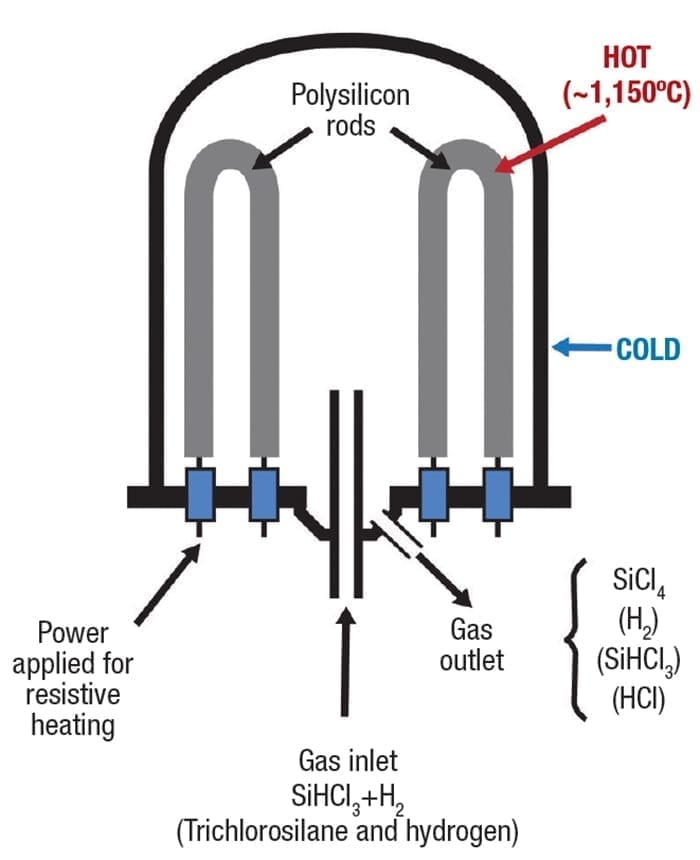
Figure 8. Through a long process of gaseous deposition, ultra-pure polysilicon builds up on the filaments
This process continues for several days, with a constant flow of the feed gases, eventually building up the filaments from a few millimeters to 200 mm in diameter. Feed gas flow and pressure must be controlled carefully to ensure the fastest material deposition without wasting unreacted gas.
This is a challenging process, to say the least. The chemicals involved are highly flammable, corrosive, toxic and react violently with water. The process is energy intensive and costly, so ensuring careful control and stability are paramount. Temperature fluctuations can cause cracking or splintering, and even the slightest contamination renders the product unusable.
For a pressure instrument, this application is as challenging as they come. Pure hydrogen at a high temperature and pressure provides all the conditions necessary to drive hydrogen permeation through a conventional stainless steel or high-nickel alloy diaphragm. This is made worse by regular cycling of the reactor, allowing pressure to drop to atmospheric when each charge is completed. Any hydrogen that migrates through the diaphragm and into the fill fluid can potentially bubble out and deform the diaphragm.
Given the extreme process temperature, an instrument to monitor gas pressure is usually located on the feed pipe, where the temperature is much lower. Nonetheless, with 5 bars pressure, conditions are optimal for creating hydrogen permeation able to cause instrument failure. This calls for gold coating on the diaphragm to minimize permeability.
Multiple solution possibilities
Hydrogen service, as discussed here, presents critical challenges fully capable of causing instrument failure. However, there are solutions that can reduce the problem, and often eliminate it entirely for all practical purposes. For users, the lesson should be that no challenge must be tolerated over the long term. Instrumentation companies are generally very responsive to the needs of manufacturers and have found many creative approaches to solve or at least manage problems that may have seemed unsolvable. The answer is engaging the vendor as a trusted partner, one with extensive domain expertise and a full portfolio of solutions.
Acknowledgment
All images courtesy of Endress+Hauser.
Author
 Keith Riley is the national product manager for Pressure and Temperature at Endress+Hauser (2350 Endress Place, Greenwood, IN 46143; Phone: 317-535-2169; Email: keith.riley@endress.com), a position he has held since April 2008. Prior to this, he was a product manager and regional sales manager with L.J. Star Inc., as well as a product manager for Penberthy (Tyco Valves). Overall, he has over 20 years of sales, marketing, and instrumentation experience in the chemical process industries.