Pumping hazardous chemicals requires specific shaft-sealing technologies to ensure containment and reliability
Hazardous chemicals are defined by the Environmental Protection Agency (EPA; Washington, D.C.; www.epa.gov) as those that are potentially harmful to human health and the environment. Existing as gases and liquids, they are manufactured, stored, transported and used throughout the chemical process industries (CPI). Handling toxic chemicals, such as ethylene oxide, toluene, butadiene, methylene chloride, xylene and scores of other acids and hydrocarbons, requires equipment that ensures process reliability and material containment. Central to this machinery are pumps, which must reliably move fluids and gases through every stage of processing.
Transporting and pumping hazardous chemicals requires a complete knowledge of their physical properties. Pumping complex chemicals like butadiene, for example, requires special attention to chemical composition, as well as the transmission mechanism and the hydraulics involved. For example, butadiene presents an extreme explosion and fire hazard when permitted to reach its vapor point (Figure 1), and has extremely rigorous requirements for its storage and handling (Figure 2). Like many other hazardous chemicals, butadiene must be refrigerated and maintained under pressure. Faults in its handling will result in pump flow restriction and a host of related operational difficulties.
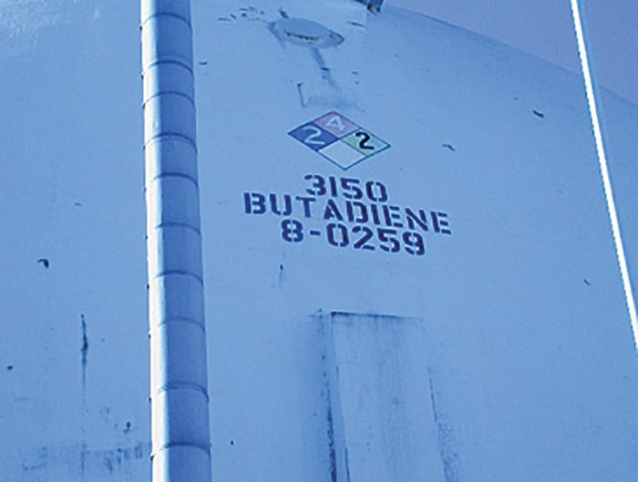
FIGURE 1. Butadiene is a crucial part of countless end products, but its hazardous nature makes it very difficult to handle and transfer without the proper combination of pump and sealing technologies
Failure of pumps and other rotating equipment in industrial processes can have dire consequences, jeopardizing environmental, health and safety (EHS) conditions at the plant. Although mission-critical equipment is typically redundant with spare pumps and spare piping, unplanned failure is extremely costly and exposes the plant to periods of un-spared operation. This increases risk and interrupts regular preventative-maintenance procedures followed elsewhere in the plant. This article examines pump-sealing ideologies for hazardous materials.
Pump seals for hazardous chemicals
Pumps handling volatile and hazardous chemicals are carefully specified, along with suction and discharge piping, to provide consistent flow and maintain a high level of control. Hazardous chemicals pose significant challenges to pump performance, and specifically to the operation of a pump’s shaft-sealing system. The transmission of hazardous fluids demands a sealing system and sealing technology that operates effectively while avoiding emissions to the atmosphere.
Pump seals are engineered to operate with specific hazardous chemicals, under known parameters of abrasive conditions, pressure changes, extreme temperatures and multi-phase fluid properties. Seals are vital to maintaining pump efficiency, reliability, energy consumption and control of emissions to the environment.
Air-quality surveys conducted in chemical plants have determined that the majority of a site’s toxic-release inventory is attributable to the shafts of centrifugal pumps. Historically, the performance of mechanical shaft seals and the sealing technology specified has had a major effect on the toxic-release survey results for a given operation. In recent years, advanced controls and the popularity of dual seals and dual non-contacting gas seals have played a major role in reducing the toxic-release totals at chemical manufacturing plants and petroleum refineries. Two very different emissions-abatement strategies have been applied to fluid transmission in recent years: sealless pumps, and non-contacting, dry-running dual-gas seals.
Sealless pumps
On the heels of the Clean Air Act of 1990, and amendments to the act implemented by local air-quality boards, the answer seemed to lie in pumps that did not rely on conventionally driven impellers. Magnetically coupled pumps or “sealless” pumps enjoyed significant interest from a large segment of the conventional ANSI pump market. The absence of a mechanical coupling theoretically eliminates any leak path between the flooded pump volute and the electric motor drive.
Two types of sealless pumps are common: canned motor pumps and magnetically driven pumps. Canned motor pumps have the windings of the electric motor built into a hermetically sealed pump body. The pump shaft and impeller are driven by a rotor winding affixed directly to the shaft. This rotating shaft is supported by bearings and surrounded by the motor’s stator winding. All of these components are hermetically sealed into a can, which forms the pump. Motor windings are cooled, and bearings are lubricated by the fluid being pumped.
Magnetically driven pumps rely on a conventional electric motor to drive a set of magnets. The driven magnets, in turn, transfer torque to a set of opposite-pole magnets that drive the pump’s impeller. The pump shaft’s magnets operate in the pumped fluid, and are hermetically sealed. Again, shaft bearings are lubricated by the fluid being pumped. The product flows through lubrication and cooling ports integral in the pump head design.
As a result of this approach, a trend developed where magnetically coupled pumps were applied wherever emissions were a potential problem. After baseline air-quality surveys found emissions levels to be out of compliance, decisions were made to limit penetrating shafts, resulting in a significant investment into magnetically driven, sealless pumps.
Conceptually, in sealless pumps, the product being pumped must assume two new roles: that of the heat-transfer fluid; and as the bearing lubricant. Unfortunately, the product being pumped does not often possess the lubricating and heat-transfer properties required to properly support the magnetically coupled equipment. This can lead to significant maintenance problems associated with sealless pumps.
The bearings of a magnetically driven pump are typically made of inert, non-metallic materials — often ceramic or silicon carbide. Of course, any bearing is intolerant of lubrication loss, but silicon carbide is particularly unforgiving of dry-sliding contact. The absence of adequate liquid volume can quickly lead to critical damage of bearings and bushings, and high repair costs. Brief seconds of dry running can result in immediate bearing failure, which is often catastrophic. In such events, impeller alignment is lost, and frequently the containment shell of the pump is in danger of rupture. Even where lubrication is thought to be adequate, hydraulic requirements of the system can place demands on thrust surfaces, wear rings and bearings that are beyond the capabilities of the process fluid. This can result in unplanned failure and increased risk of containment rupture.
The application of magnetically driven pumps requires a thorough understanding of their hermetic technology, as well as a precise familiarity with the fluid being moved. Some modern magnetically driven pumps apply ceramic containment shells to serve as the can containing the drive elements of the magnetic coupling. This strategy has been applied to combat problematic eddy currents and localized wear that can occur with conventional alloy canisters.
Non-contacting dry-gas seals
Introduced in the 1980s, non-contacting, dry-gas seals have become standard in the industry for pump seals handling hazardous chemicals.
Spiral-grooved dry-gas seals are non-contacting, dry-running mechanical face seals that consist of a mating ring and a primary ring. Typically, the grooved face (mating ring) is stationary and the ungrooved primary ring is rotating. Seal arrangements vary, and often there are requirements for the ungrooved face to remain stationary.
In either arrangement, a spiral groove pattern will compress an inert gas to produce a hydrodynamic lifting force, allowing the stationary face to separate and operate with a small gap, which is effectively lubricated by the inert gas that serves as a barrier fluid. In recent years, dual non-contacting gas seals have featured spiral grooves at the inner diameter (I.D.) of the seal face. The inboard seal is pressurized on the I.D. with barrier gas. The arrangement differs from conventional outer-diameter (O.D.) pressurized gas seals. This arrangement can further enhance the behavior of the seal by placing the liquid being sealed at the O.D. of the faces, effectively eliminating the possibility of de-watering and drying of the process fluid. Process fluid drying and de-watering, as well as changes in viscosity, which can happen with conventional dual seals, are a significant root cause of failure.
Non-contacting dry-gas seals typically use an inert barrier gas supplied at roughly 25 psi above stuffing box pressure. Barrier gas is supplied as a dead-headed source of inert gas. When the shaft is not turning, the spring-energized seal faces contact the un-grooved portion of the mating ring, effectively forming a static seal.
Non-contacting seals are gas lubricated. The barrier gas provides a stiff lifting force to both primary rings of the seal, eliminating contact and, as a result, friction. Spiral grooved non-contacting seals generate virtually no heat. The double seal arrangement and pressurized barrier gas offer a zero-emissions solution, while maintaining product purity. These seals are suitable for use in harsh working environments that must handle hazardous chemicals (Figure 3).
No emissions, increased uptime
Pumps that handle hazardous chemicals are subjected to the rigors of abrasive conditions, pressure changes and extreme temperatures, and therefore, can be prone to axial movement over time, a condition under which many seal designs can fail.
Dry-gas seal designs that incorporate a rotating mating ring are better able to tolerate radial movement and imperfect pump-shaft excursions over time. Ultimately, a non-contacting gas seal does not develop a wear pattern. This delivers a more tolerant seal and results in significantly improved uptime when compared to sealless pumps.
Of considerable importance where non-contacting dry-gas seals are applied is the preservation of product purity. Often, the product stream is finished or nearly complete. Additionally, product streams can be sensitive to seal lubricants and barrier or flush liquids. Examples of ultra-high purity requirements include special polymers, food and flavor ingredients and even water that is used for intravenous injection. Preserving product purity is a key driver, and often eliminates filtration and costly liquid-extraction activities.
Butadiene handling
Perhaps no chemical presents a better example of the necessity of secure transfer and purity than butadiene — a suspected human carcinogen that presents severe fire and explosion risks. Despite the associated risks, butadiene is crucial in producing myriad end products, from car tires to shoes to toothbrushes.
This specific case concerns a plant in the U.S. that produces styrene monomer and uses butadiene to create a variety of synthetic elastomers. In this plant, butadiene is purchased from an ethylene plant on the U.S. Gulf Coast and delivered by railcar to a pressurized and refrigerated sphere (Figure 2). The pure butadiene is moved from the sphere to weigh tanks, where exact proportions are determined prior to its placement in large agitators. The agitator receives the proper amount of various other ingredients required for the finished product.
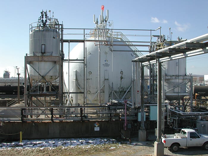
FIGURE 2. Butadiene is often stored in specialized spherical vessels that maintain the proper pressure and temperature to ensure safe and reliable processing
Moving butadiene, or any chemical, requires a knowledge of its physical properties. To pump butadiene, it must be maintained in its liquid phase. The material presents hazards that are quite serious. In addition to its EPA status, butadiene is a known risk to human health and presents an extreme explosion and fire hazard when permitted to reach its vapor point. When phase change occurs, a low-grade rubber begins to form, and this mechanism is responsible for significant reliability challenges with rotating equipment. Operationally, butadiene must be refrigerated and maintained under pressure. Improper handling will result in spontaneous rubber formation, flow restriction and a host of related operational difficulties. Maintenance of rotating equipment that handles butadiene must include a thorough consideration its physical and chemical properties.
The serious health risks with low-level butadiene exposure and extreme flammability have been understood by users for years. The emergence of challenging emissions standards in the early 1990s placed an element of immediacy on fluid-control equipment trends. Operations that handle butadiene are strictly monitored by the EPA and local air-quality agencies. The stakes are very high, and release of product is forbidden. Unit shutdown — or even a whole plant shutdown — can be mandated if emissions rise to a level that is reportable.
As described in this article, in the wake of the Clean Air Act of 1990, a trend developed where magnetically coupled pumps were applied wherever emissions were a potential problem. In this case, the butadiene plant employed logic that can now be characterized as typical in the industry. After baseline air-quality surveys found the company to be out of compliance, decisions were made to limit penetrating shafts. A significant investment was made in sealless pumps for the butadiene recirculation loop.
At this particular site, reliability engineering leadership chose magnetically driven pumps to handle butadiene recirculation. Liquid butadiene was pumped from a railcar to a storage sphere. The sphere was pressurized above butadiene vapor pressure at around 50°F, or roughly 20 psi. Recirculation was required in order to maintain the butadiene in its liquid state. In the summer, the product was refrigerated; in the winter, it was heated to maintain 50°F. In the absence of recirculation, butadiene will destabilize and liberate a product referred to as dimer. A thick, dark-colored polymer, dimer works as an inhibitor while the butadiene is in its liquid phase. With phase change from liquid to gas, the dimer plates out to form a tacky, viscous synthetic rubber. The prevention of phase change is key to avoiding operational problems.
The requirements of recirculation are not particularly challenging. The fluid is continuously moving from the sphere to either a chiller or heater to maintain temperature and the all-important liquid phase. Since the sphere is never empty, the pumps never run dry.
From the sphere, the butadiene is transferred to weigh tanks and subsequently to agitators for the production of batch product. Moving the liquid butadiene from its storage area to the production area requires significantly different hydraulics. For this product feed duty, centrifugal pumps (Figure 3) were chosen (one primary and one standby spare). Emissions guidelines at the plant demanded the use of a dual pressurized seal. The possibility of localized temperature rise and the conscious avoidance of wet-seal lubrication led reliability engineering staff to choose non-contacting, dry running seals for this application.
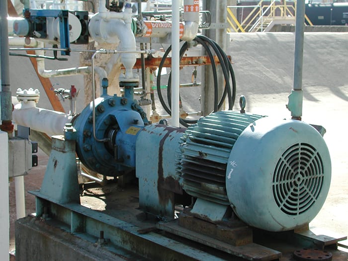
FIGURE 3. Pumps that handle hazardous materials can be equipped with non-contacting dry-gas seals to improve fluid transfer and safety
This installation offered an opportunity for a pragmatic and reasonable comparison of two very different pumping technologies applied to a very challenging liquid.
Prior to installation of the new seal, the pumps were thoroughly inspected. Although the pump shafts were found to have 0.010-in. runout radially, this runout was occurring between bearings and would not affect the impeller, bearing journals or the coupling. The seal is a rotating seal cartridge that offers a somewhat more tolerant arrangement, therefore these real-world and less-than-ideal characteristics of the pump shaft were considered to be acceptable. The seal chamber bushing and the pump impeller’s wear ring were replaced and refit. After the seal was installed, it was bench-tested to ensure that the static O-rings were intact and not damaged.
In preparation for startup, seal chamber pressure was calculated using the customary method associated with the pump manufacturer’s installation and operating manual. Nitrogen barrier pressure would be set at approximately 30 psi above the seal chamber pressure. An important feature of calculating seal chamber pressure on this particular pump model is that the actual seal chamber pressure can be significantly greater than the calculated value. The condition of wear rings and bushings, as well as the style and size of the impeller affect the hydraulics of all pumps. However, this particular pump model is notorious for developing higher-than-calculated seal chamber pressure. Where feasible, reliability engineering or maintenance staff should gauge seal chamber pressure and set barrier pressures appropriately.
In the five years since commissioning the butadiene feed pumps, the standby pump has never been called upon, and maintenance costs have been significantly reduced. In contrast, the magnetically driven recirculation pumps have been burdensome. Preventive maintenance activities revealed a number of problems, and hydraulic demands have resulted in badly worn thrust pads, wear rings and bearings. Containment shell erosion is a significant concern as a result of magnetic particle carry over from rail cars. The applications are certainly different — recirculation is somewhat less rigorous than intermittent feed or transfer duty — but the economic comparison in this case clearly favors conventionally coupled equipment.
Edited by Mary Page Bailey
Author
Michael Kalodimos is global product manager at John Crane, Inc. (6400 Oakton St, Morton Grove, IL 60053; Email: mgkalodimos@johncrane.com). He specializes in work related to spiral-groove technology and various seal-face finishing technologies. He has served in a number of manufacturing, engineering and marketing roles since joining the company 35 years ago. Kalodimos received a B.S. in industry and technology from Northern Illinois University.