By making it easy to detect heat anomalies, thermal cameras and infrared thermometers support preventive and predictive maintenance
Rising temperatures and rapid or excessive heat buildup are useful markers for determining the operational health of many types of machinery and components that are used in a wide array of industrial and manufacturing settings. The types of mechanical and electrical systems for which temperature increases often signal problems include (but are not limited to): rotating machinery, such as motors, turbines, compressors, and their bearings, couplings and gearboxes; other types of process equipment, such as pumps, valves, heat exchangers, steam traps, heaters, conveyors belts, rollers, furnaces and more; steam and electrical heat-tracing systems; insulation on pipes and vessels; refractory lining systems for high-temperature systems and much more.
Because equipment malfunctions and abnormal or fault conditions in mechanical and electrical systems are often forewarned by a rise in temperature, the ability to gather and analyze temperature data in realtime can often help operators to both pinpoint existing performance-related issues and identify the onset of incipient problems. These problems can be caused by an array of issues, including wear, imbalance, misalignments, insufficient cleaning or lubrication, friction and electrical problems.
The traditional approach to temperature monitoring in industrial settings relies on direct-contact temperature sensors, such as thermocouples and resistance temperature detectors (RTDs). While these devices are certainly proven and accurate, they are not appropriate for use with certain types of equipment components or in some types of industrial settings.
 |
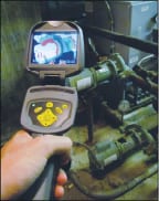 |
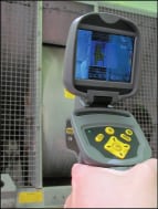
By contrast, remote or non-contact temperature-measurement devices, such as infrared thermal-imaging cameras and infrared thermometers (IRTs) allow useful temperature data to be easily gathered from remote locations and thus offer a useful alternative to direct-contact temperature sensors. The ability to safely carry out temperature sensing from a distance, using either a thermal camera or an IRT, is particularly useful for machinery components and systems that may be hard to reach, inaccessible, or potentially hazardous. In this way, these temperature-monitoring devices help to enable realtime temperature measurement while ensuring worker safety (Figures 1 and 2).
Technology options
The two types of remote thermal-sensing options — infrared thermal-imaging cameras and IRTs — are widely used for temperature assessment in industrial and manufacturing facilities. In addition, two different types of IRTs are available — conventional IRTs, and so-called scanning IRTs. Used separately or together, these devices can help users across numerous industry sectors to quickly and easily assess the thermal condition of machinery, process systems, pipelines and more.
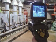
Conventional IRTs are best suited for applications that require accurate spot-temperature readings, while scanning IRTs and thermal cameras are useful for applications for which knowing the absolute temperature of a surface is less important than knowing the temperature of a particular surface relative to other surfaces around it. The primary advantage of a thermal camera is its ability to display the thermal spectrum of an entire area, as seen in Figure 3.
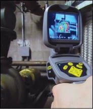
Infrared thermal-imaging cameras. Portable thermal-imaging cameras are easy to use, and typically come with a pistol-grip design, as seen in Figure 4. They use infrared-imaging techniques to measure the surface temperatures of the objects or areas being analyzed and can render the data in the form of two-dimensional images or videos images to illustrate the data. Specifically, these specialized cameras measure surface temperature in terms of the amount of infrared (IR) energy that is emitted, transmitted and reflected by the object or area being analyzed. The temperature data are displayed as an IR heat spectrum, using a range of colors that are correlated to specific temperature ranges. Today’s thermal cameras have great sensitivity, and provide measurement accuracies of up to ±2°F.
Thermal cameras produce a thermal signature or thermogram, which is a two-dimensional visual display that depicts the relative temperature variations across the object’s surface. These images allow operators to quickly pinpoint problem areas, since temperature excursions, such as areas of heat loss or heat gain relative to the surroundings, are easily displayed through color variations in the rendered image.
Such visual displays of relative temperature variations across the surface of the objects gives operators and technicians unprecedented insight into the health of equipment and systems, and help to address emerging problems efficiently. Thermograms are especially useful when thermal imaging is used as part of regular inspections, because they allow engineers to quickly recognize changes that may signal an emerging problem. Thermal images that are captured and analyzed over time for the same component (for instance, a given motor or pump) can help users to identify locations of incipient malfunction or progressive wear or deterioration.
Creating such a record of heat buildup due to deteriorating conditions allows operators or technicians to dispatch the most appropriate intervention in a timely manner. These interventions include detailed inspection, troubleshooting and diagnostic efforts, and strategic maintenance and repair activities. Because thermal imaging is carried out at a distance, it enables the capture of thermal data from components that are in remote or hazardous areas, thereby ensuring worker safety.
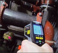
Infrared thermometers. IRTs are portable, non-contact devices — again, typically with a user-friendly, pistol-grip design. IRTs use a special lens to focus the thermal radiation that is being emitted by the object (in the form of IR energy) onto an IR sensor. The embedded software correlates those IR readings to the temperature of the object using information about the material’s emissivity. Like thermal imaging cameras, IRTs offer an ideal way for operators to determine the temperature of hot or cold surfaces remotely, which is especially useful for inaccessible or hard-to-reach objects or areas.
As noted earlier, two types of IRTs are available — conventional “spot” IRTs and so-called scanning IRTs. Scanning IRTs allow users to scan an entire area or system and quickly identify those sections where there is a significant temperature differential between the actual temperature of that section and a pre-set temperature setpoint value that the user has programmed into the device.
Using a conventional IRT with an appropriate distance-to-spot (D:S) ratio — one that allows the measurement “area” to be entirely focused within the object being measured — plant personnel can determine the temperature of an object at a single spot. A built-in laser-beam sighting source helps the user to focus the device on the target precisely, to ensure measurement accuracy.
While conventional IRTs are useful for remotely gathering point-source data about the absolute temperature of a given spot, scanning IRTs are useful for applications where it is not necessarily important to determine the absolute temperature of a surface, but it is useful to determine the relative temperature of a surface or area compared to its surroundings.
Today’s scanning IRTs are not only very affordable (typically under a hundred dollars, compared to more than a thousand for thermal cameras), they are also extremely easy to use. With a point-and-shoot design, the user first establishes a baseline temperature that is appropriate for the application, after which an acceptable bandwidth or tolerance range is set — for example, ±10 degrees, although tighter tolerances of ±1 or ±5 degrees are possible.
When the trigger on a pistol-grip scanning IRT is squeezed and the device is moved slowly across the target area, the device uses a combination of sound (in the form of slower versus faster beeping sounds) and colored lights (for example, red for above range, green for within range, and blue for below range) to alert the user to any location where the temperature falls outside of the user-specified threshold values that define the setpoint range. The IRT will also provide an absolute temperature reading for that particular spot.
While scanning IRTs do not produce a thermal image, they do provide a quick, easy, and relatively inexpensive way for facility personnel to assess specific mechanical assets and identify those problem areas that may require closer inspection.
A valuable investment
 |
While individual thermal cameras typically cost more than a thousand dollars, they can be a strategic investment — and will easily pay for themselves over a short amount of time if their use prevents a catastrophic failure.
As noted, the use of remote, IR-based thermal sensing to inspect, troubleshoot, diagnose and rectify problems with specific equipment in realtime can help facility operators to improve the efficiency and effectiveness of both component-specific and plant-wide operation and maintenance (Figure 5). Such improvements provide a number of opportunities for long-term savings and payback. For instance:
• The costs associated with unplanned downtime in industrial facilities, such as manufacturing plants and chemical process facilities can be greatly reduced when thermal imaging is used to improve preventive and predictive maintenance tasks
• Proactive troubleshooting and diagnostic intervention can help to decrease the likelihood of expensive or catastrophic equipment failures — especially important when considering mission-critical assets
• The ability to plan and execute more-strategic repairs helps to cut material and labor costs and extend equipment life, thereby helping to reduce both operating and capital budgets
• Increased uptime allows the facility to maximize its throughput capacity, product yields and profitability. The ability to carry out strategic maintenance activities helps to not only save money, but improve plant and personnel safety and environmental performance
Best practices
There are several ways to make best use of thermal-imaging data. Trending opportunities can be used to the engineer’s advantage. For instance, the thermal signature from a given component, such as a particular pump that may be suspected of having a problem, can be compared to the thermal signature of similar pumps in the facility. This will help to evaluate its condition relative to other equipment with comparable operation.
In addition, the thermal images generated for a given mechanical asset (say, a particular motor), can be strategically captured and cataloged over time in specific intervals. This record can provide timely indications of deteriorating conditions and help the operator to make reasonable predictions about the rate of future deterioration, so that the required action — be it maintenance, repair or replacement — can be carried out, at the appropriate time, in the most cost-effective manner.
When practical, it is a good idea to carry out baseline thermal-imaging inspections on new components, to establish baseline or reference images that represent the component’s ideal state under normal working conditions. Going forward, any departure from normal temperatures that appear in the thermal images produced for the unit would signify trouble spots that require closer inspection.
Proper training and certification are extremely beneficial when using IRTs and thermal-imaging cameras. While these devices are typically simple to operate and provide data and images that are easy to interpret, both rely on sophisticated technology. As such, to ensure the most accurate results, users should gain a good working knowledge of the capabilities and limitations of these tools through proper training and certification. Without proper training, the accuracy of the resulting thermal data and images could be compromised. Following vendor-recommended operating guidelines and proven industry best practices is a must for data confidence.
Today, a variety of third-party groups offer training and certification in the proper use of thermal-imaging cameras, including the American Society for Nondestructive Testing (Columbus, Ohio; www.asnt.org), the Academy of Infrared Training (Bellingham, Wash.; www.infraredtraining.net), the Infraspection Institute (Burlington, N.J.; www.infraspection.com), The Snell Group (Barre, Vt.; www.thesnellgroup.com) and others.
Choosing the right thermal imaging camera for the environment has an effect on the equipment’s ability to best collect accurate data. Thermal imaging cameras are widely used to carry out energy-efficiency studies and audits in residential, commercial and business settings, by helping to identify areas through which heated or cooled air is escaping from a building. Industrial facilities can also use these devices to carry out energy audits to identify further opportunities to reduce operating costs.
When this is done, users should note that regional climate variations can impact what time of year the use of a thermal imaging camera will be most effective. For instance, in northern climates, the use of thermal imaging to carry out energy audits at a facility tend to be most accurate when carried out during winter months (when the temperature differential between indoor and outdoor temperatures is the greatest) and temperature differentials resulting from the unwanted ingress or escape of heated or cooled air will be most easily identified by the thermal camera or scanning IRT assessment. By contrast, in southern climates, the summer months tend to guarantee the biggest temperature differential between ambient outdoor temperatures and air-conditioned settings.
This potential seasonal “limitation” can be somewhat overcome by selecting a higher-resolution thermal camera. Today, a variety of thermal cameras — with a range of prices and image-resolution capabilities — are available. Relatively low-end models have sensors with a resolution of 60×60 pixels. Mid-range units have a resolution on the order of 160×120 pixels, and high-end thermal cameras offer a resolution of 360×280 pixels.
While lower-resolution thermal cameras may be available at a lower cost, the desire for cost savings alone may “cost” the buyer in the long run by limiting the number of months over which the camera can be reliably utilized to carry out energy audits and other types of thermal inspections. In general, the higher the resolution of the thermal camera, the more reliably it can depict a thermal difference when carrying out a thermal assessment — even during those times of the year when the temperature differential between indoor and outdoor temperatures is relatively narrow. By investing in a higher-resolution camera, users will be assured of greater sensitivity and easier thermal assessments no matter what climate or time of year. This helps to ensure more accurate results and faster payback for the camera itself.
Another important factor to consider when using thermal cameras and IRTs is the relative emissivity values of the materials being surveyed. Emissivity is a measure of an object’s ability to absorb or reflect radiation in the infrared range of the electromagnetic spectrum. As a simplifying assumption, many thermal cameras have fixed emissivity values that are associated with certain commonly encountered materials programmed into the control software.
However, today’s more-sophisticated thermal-imaging cameras allow the user to make adjustments to the emissivity settings, to more accurately characterize the actual emissivity values of the materials being analyzed. Such values can often be found in published books and reference articles. This flexibility can help users to improve the accuracy of the resulting thermal images.
Certain surfaces, such as highly reflective metals, have very low emissivity values and cannot be measured accurately using IR-based temperature-measurement techniques. To overcome this problem and improve the utility and accuracy of IR-based thermal cameras and thermometers, industrial operators often paint the target surfaces or cover them with electrical tape. This raises the emissivity values of the components and improves the accuracy of the IR-based thermal imaging techniques.
 |
When it comes to evaluating different IRT models, an important concept to consider is the distance-to-spot (D:S) ratio (Figure 6). This characteristic of the device provides a measure of the optical resolution that a particular unit can provide. Every IRT model has a stated D:S ratio, which determines the distance for which the device will provide the most accurate temperature reading as well as the diameter of the imaging area. For instance, most standard IRTs have a D:S ratio of 8:1. This indicates that an IRT 8 in. away from the object can accurately measure the temperature at a spot that is 1 in. in diameter. Similarly, an IRT that is 48 in. away from a target will measure the temperature within a circle that is 6 in. in diameter.
Units with a D:S ratio of up to 100:1 are also available. In general, the higher the D:S ratio of the device, the smaller the zone for temperature capture, because less of the surrounding area is involved in the measurement. IRTs with higher D:S ratios also provide for more accurate readings to be gathered from greater distances.
Closing thoughts
Remote, non-destructive, thermal-sensing techniques, using IR thermal cameras and scanning or conventional IRTs, provide useful alternatives to direct-contact temperature devices based on RTDs and thermocouples. They provide useful information on temperature excursions that are often the precursor to operational problems, allowing users to plan the most strategic predictive and preventive maintenance activities and to carry out the most cost-effective repairs and upgrades. Such efforts can help to optimize the productivity and reliability of the mechanical assets, maximize the uptime of the facility, and minimize downtime-related losses and expenses and reduce the risk of catastrophic equipment failures. And, remote IR-based temperature monitoring lets facility personnel carry out such surveillance without shutting down the machines, interrupting the process or putting themselves in harm’s way. This maintains equipment reliability, the facility’s desired productivity levels, as well as personnel safety, and thereby helps to protect the facility’s bottom line.
Acknowledgements
The authors would like to thank John Javetski, Adrian Gomez, Kevin Basso and Peter Harper of General Tools & Instruments for their assistance during the development of this article.
Authors

Roger Mavrides was formerly vice president of engineering and product development for General Tools & Instruments (80 White St., New York, N.Y. 10013; Phone: 1-800-697-8665 x222; Email: gentools@generaltools.com). He holds a Certificate of Electronic Maintenance (CEM) from Wentworth Institute of Technology, a B.S. in electrical engineering technology from Northeastern University and an M.B.A. from Anna Maria College. Before joining General Tools, Mavrides was engineering and product manager, test and measurement, for FLIR Systems (Nashua, N.H.), sales and product manager for Nidec/Power General (Canton, Mass.), and senior design engineer and project manager for Vishay/BLH Electronics (Norwood, Mass.). Mavrides holds three patents, is a Level 1 Thermographer, and was a team leader during the development of FLIR’s MeterLink communication protocol. He also developed a wireless alternating-current circuit identifier that won a Hong Kong Electronic Industries Association (HKEIA) Innovation and Technology Grant Award at the 2009 HK Electronics Fair, and developed an electrically safe video borescope that won the Bronze HKEIA Innovation & Technology Grand Award at the 2011 HK Electronics Fair.

Suzanne Shelley is the principal/owner of Precision Prose, Inc. (65 West 96th St., Suite 21F, New York, N.Y. 10025; Phone: 917-975-2778; Email: SuzanneAShelley@yahoo.com). In that capacity, she provides freelance technical writing, ghostwriting and editing services (specializing in science, engineering, technology and business) to magazines and corporate clients. Prior to launching her consultancy in 2005, Shelley spent 17 years as a full-time editor at Chemical Engineering magazine, serving as the magazine’s managing editor for her last 5 years on staff. As a freelance writer and editor, Shelley serves as a regular freelance contributing editor at Chemical Engineering and Pharmaceutical Commerce magazines, and as a periodic freelance contributing editor at Chemical Engineering Progress (CEP; AIChE). From 2005–2009, she also served as a regular contributing editor to Turbomachinery International magazine. Shelley also provides freelance writing, ghostwriting and technical editing services to a wide variety of operating and service companies, consultancies, advertising agencies and trade associations throughout the global chemical process industries. She holds a B.S. in geology from Colgate University (Hamilton, N.Y.) and a M.S. in Geology from the University of South Carolina (Columbia, S.C.), and worked as a deepwater exploration geologist in the Gulf of Mexico for Amoco Production Co. (New Orleans) in the late 1980s.