Follow this guidance to improve the operation, safety and reliability of rotating machinery in chemical process plants Troubleshooting problems in rotating machinery (such as compressors, pumps, steam turbines, gas turbines, turbo-expanders and more) can present difficult challenges during day-to-day operations in facilities throughout the chemical process industries (CPI). Reliable operation is an important factor in keeping plants running, particularly as plants push to operate at higher capacities. Lost profits due to persistent machinery problems can never be recovered. Rotating machinery often presents the most difficult operational problems in a CPI plant. This article provides a practical, in-depth review of the art and science of machinery troubleshooting and problem solving. Five case studies are presented to cover a variety of relevant rotating-machinery systems, such as compressors, pumps, gas turbines and steam turbines. All of the case studies presented here were developed from actual field experience. This article offers a broad working knowledge of troubleshooting principles and practice, to help operators gain insight into different techniques and various methods for machinery problem solving.
A systematic approach
Proper CPI plant operation requires sustained attention to the following:
- Identifying opportunities to improve machinery reliability and safety
- Developing solutions for chronically problematic rotating machines
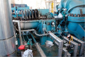
FIGURE 1. Shown here is a steam turbine dismantled for repair. This is the driver of the centrifugal compressor
A systematic approach is the key for solving any machinery operational problem. Comprehensive machinery assessments should be carried out using advanced data-collection tools and methods (Figure 1). For instance, the use of automated machine-data-collection software — which automatically collects a wealth of information specific to the machinery component — coupled with sophisticated modeling techniques, can provide great insight to support troubleshooting efforts related to complex rotating machinery. Such insight can help operators to diagnose the actual root causes of underperforming machinery and premature machinery failures. When CPI operators rely too heavily on alarms and trips, there is limited time to take remedial action in response to a machinery issue. Instead, a proactive monitoring approach provides greater value, by enabling earlier machinery troubleshooting through improved early detection of unusual deviations. This can provide an earlier indication of problems that may be developing. In modern operations, expert operators often opt to manage critical machine components using time-based data trends. Useful trends can be developed when the behavior of individual performance variables, such as pressure, temperature, flow, lubrication oil characteristics and more, are plotted over time on a graph. These trends can then be analyzed in conjunction with additional information, such as that derived from alarm screens and plant control-system graphics. By monitoring trends, operators can anticipate potential problems and propose smart solutions before any major upset occurs. Trends in relevant data can support operators and machinery engineers, allowing them to stay aware of situations as they begin to arise, diagnose the root cause of problems and resolve abnormal situations. The ability to gather and analyze trend data can also help operators to compare past and present behavior, thereby supporting efforts to anticipate future changes.
Keep an eye on key variables
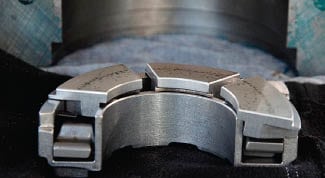
FIGURE 2. Tilting pad thrust bearings are widely used in relatively high-speed rotating machinery. These bearings are vulerable and can be damaged easily; shown here is one that was removed for repair
Vibration monitoring is an important indicator that can help operators to identify machinery problems at an early stage. The location of vibration sensors is vital, to avoid introducing errors during the measurement. In general, the best location for vibration sensors in rotating machinery is at the bearing or bearing housing (Figure 2). Vibration measurements at the machinery casing, in addition to bearing vibration, can provide useful data for identifying and solving machinery problems. However, monitoring vibration alone is not sufficient to gauge the health of rotating machinery especially when large, critical machines are concerned. For instance, in a recent case, it was observed that one electric motor’s temperature and current increased when the machine was overloaded — well before any vibration was detected. This underscores the importance of monitoring other parameters (such as temperature and current), in addition to vibration, to allow for early fault diagnosis of electric machines. When vibration analysis is used alone, it may be difficult to establish the real cause of the vibration. In general, it is better to monitor both vibration and overall machinery performance (such as delivered pressure and flow in pumps or compressors) to obtain a more reliable fault diagnosis. And, it is important to realize that the vibration produced by the machinery is not a fault on its own — but rather a symptom (and early warning sign) of a developing failure condition. Temperature is another critical variable, and the ability to monitor it accurately is of paramount importance in CPI plants. Today, a wide range of temperature sensors and measurement systems exists, including thermocouples, resistance thermal detectors (RTDs; also known as resistance thermometers), thermistors, filled thermal systems, pyrometers, infrared thermography techniques and glass thermometers. All are widely used to provide process and machinery temperature measurements. The measurement of flowrate provides another useful indicator for the health of many processes and machinery systems. Traditionally, techniques based on differential pressure, turbine and vortex shedding have been used to measure fluid flowrate. However, these methods might not be suitable if an accurate measurement is required for gases, since errors can be introduced in the measurement due the compressible nature of gases. To use these methods with gas flows, it would be necessary to compensate for the gas density fluctuation in order to reduce the errors. Modern Coriolis mass flowmeters are a more appropriate choice for measuring gas flowrate, which is usually independent of temperature, pressure, density and composition. This meter uses the Coriolis effect to measure the amount of mass moving through the element. In a simple form, the fluid to be measured runs through a U-shaped tube that is caused to vibrate in a perpendicular direction to the flow. Fluid forces running through the tube interact with the vibration, causing it to twist. The greater the angle of the twist, the higher the flow. These flowmeters have no rotating parts. Modern Coriolis flowmeters are highly accurate (providing accuracy to around±0.5% of the mass flowrate). For relatively low-speed rotating machines, vibration analysis may not be suitable to detect degradation or operational problems. However, acoustic-emission sensors, strategically located on the machine, can give operators early indication of deterioration in the machine’s operating condition. Control valves are vital components in every process and in many types of equipment packages where fluid is handled and regulated. However, the most common malfunction with control valves is internal leakage, which cannot be detected easily. Internal leakage can result from one of several factors, including an eroded valve plugs or seats, or insufficient seat load.
The importance of monitoring
In one situation, a CPI company avoided an estimated $10 million in property damage and business-interruption loss in a year as a result of the early detection of high vibration levels in its rotating machinery. The high-vibration monitors indicated the deteriorating conditions (a developing problem) within a large, critical compressor train. The developing problem resulted in the loss of half of the bolts, a circumferential crack in the coupling spacer (about 80 mm long) and a radial crack emanating from the initial break at the time of shutdown.
If the fault had progressed and all of the bolts had sheared before operator intervention, the compressor would have been unrestrained — with potentially disastrous consequences. This clearly illustrates why, particularly in large CPI plants, it is vital to monitor critical components on a continuous basis.
Five case studies
Case study 1: Insects in an air-compressor inlet filter. In a CPI plant in a remote area, insects caused problems for the inlet-air filtration unit of a large process-type air compressor. The accumulation of insects on the filters led to high differential pressure in the unit, leading to periodic compressor shutdowns. Multiple cases of surge and surge-related trips occurred because of this issue. Regarding a problem of persistent insects impacting the air-compressor, two solutions should be considered:
- A multi-sided insect screen. For example, three-, four- or five-sided insect screens can be constructed (for instance, in a cube or similar configuration) in the front of the air filter, with a surface area roughly three to four times that of the front face of the air filter inlet. The rationale is that insects will gather on the larger-surface area of the screen (far from actual intake) and thus experience less intake air velocity, allowing them to fly away, reducing their opportunity to trap and plug the air filter. When a screen is built with three times the area of the air intake, the air velocity across the insect screen would be around 33% of the original velocity. When the screen is built at four times the intake area, the air velocity across the screen would be just 0.25% of the original velocity.
- Specially designed pulse-clean filters. Another possibility is to install pulse-clean filters that apply a periodic reverse pulse of air to dislodge the accumulated dirt and insects from the filter inlet at a pre-disposed differential pressure. This will require a specialized filter assembly with a compressed-air supply and associated equipment and controls. However, this solution is not usually recommended since this is a complex, expensive and risky option.
In this case study, the first proposed solution was used and a four-sided insect screen was built. For such an installation, the mesh size should be selected properly to stop the smallest anticipated insects from penetrating, and it should be reasonably rigid to allow for cleaning with a soft brush. If the mesh has a dense or tight weave (say, with holes around 1-mm dia.) to ensure that small insects cannot pass through, then it may be necessary to compensate with increased surface area (so that air intake is not impeded and pressure drop is not increased). For this case, a window screen mesh (with holes roughly 1-3-mm dia.) was selected. Routine inspections by technicians have been required to clean the screen. The structure of the insect screen was made rugged enough to resist wind and ensure longevity of the asset. This insect screen provides an added benefit, by helping to keep rain and dirt from being driven into the filter inlet by wind. Case study 2: Discrepancies in performance maps. During the commissioning stage of a CPI plant, it was noted that there were two different sets of performance maps in the manual for a particular, critical centrifugal compressor — one from the compressor manufacturer and another from the anti-surge-system sub-vendor. The compressor had been delivered three years earlier but it was not installed and commissioned upon delivery because of a three-year delay in the project and a stop in the plant construction. Some of the engineers who had worked on this machine and associated unit had left their jobs and there was no proper documentation to clarify how this discrepancy originated. At this facility, there were concerns about surge. During the initial period of operation, the compressor was tripped several times because of surge or other operational issues related to the existence of two different performance maps and the allowable operating range. Any attempt to identify which performance map and surge line were the most appropriate for use failed because of personnel changes at both the compressor vendor and the anti-surge- system sub-vendor during the 3-yr period. In general, turbocompressors should be surge tested once they are installed, to develop accurate, as-built surge lines. For this machine, it was decided to perform the surge test at the site to identify the surge line and the correct performance map. This test was completed by hooking proper surge-detection hardware into the compressor’s vibration-monitoring system. At each operating speed, the compressor discharge valve was slowly closed. Prior to the surge, the surge-detection system (using vibration sensors as part of the compressor vibration-monitoring system) detected an increase in low-frequency vibration, which indicated the onset of surge. This was used to define the surge line. The compressor was not actually surged, just taken to the point of onset of stall. Once the as-built surge line was identified using this technique, it was seen to be different from what both the vendor and the sub-vendor indicated in their respective performance maps. Often, it is common to obtain a site-tested, as-built surge line that differs from the vendor-calculated surge line, or even the shop-tested surge line, because of different compressor piping and arrangement in the vendor shop test compared to the final site installation. The site-tested, as-built surge line should be considered the most reliable data for any operator. Case study 3: Re-rating a steam turbine.The steam turbine driver of a large pump train in a CPI unit created a bottleneck that prevented the unit from achieving a desired 5% increase in capacity. The operation team asked to run the steam turbine using 49-barg steam instead of 46-barg steam to achieve higher power generation from the turbine and higher pump capacity. Simulations showed that using 49-barg steam, it was possible to generate higher power, and this modeling also showed that the pump train could handle higher power and generate more flow within the pump curve. In fact, this investigation showed that the new pump operating point was a bit closer to the best efficiency point (BEP) than the old operating point. In general, significant engineering assessments are required in order to re-rate a steam turbine. The steam turbine casing in this case was originally designed and rated to 46 barg. In order to increase the pressure rating, the design of the casing was checked by both the vendor’s engineering team and an independent consultant. It was determined that it could safely and reliably contain steam at 49 barg. The casing was re-rated, after a proper hydro-testing, as per code requirements. Using the same rotor, the pressure drop per stage was increased. The existing impellers were checked to ensure that they were strong enough and the rotor did not require changing. Simulations and investigations showed that diametric changes and changes to internal static components within the casing were not required. The steam turbine was re-rated for 49 barg. The steam-turbine-driven pump train has enjoyed smooth and trouble-free operation since re-rating after the changes were made. Case study 4: Inlet filter for gas turbines. In general, gas turbines “ingest” different materials depending on the location and the plant — primarily dirt and dust, but also ice, rain, snow and salt. The cleanliness of a gas turbine is the key factor in its efficiency, reliability and safety. Accumulated dirt in the air-compressor section of a gas turbine can increase fuel consumption, and lead to more frequent maintenance outages and a decreased hot-section life. At a given CPI plant, gas turbines were used to both generate power and drive the gas compressor. The original air filters were used in these gas turbine air-inlet systems, which mandated turbine shutdown and offline water washing every six months. The dirty air reduced the efficiency of the gas turbine fleet between cleanings. For instance, the gas turbine trains exhibited efficiency drop of as much as 2.5% on average in the three-month period before each offline water washing. The scheduled offline water washing every six months on each gas turbine of the CPI plant (just for cleaning), in addition to other outages for inspection and maintenance, was wasteful and non-productive. The operation team asked for a solution. Getting maximum performance and reliability out of a gas turbine requires keeping the blades clean in order to reduce drag and improve the heat rate and power output. Inlet air filters play a significant role in the degree of fouling that gas turbines experience. With the original, older-style air filters, the operators of this plant were faced with a tradeoff: Installing higher-efficiency filters that remove more of the airborne particles creates a higher initial pressure drop and typically have a shorter life span compared to lower-efficiency filters. The filter pressure drop decreases the density of the air going to the gas turbine, which reduces the gas turbine’s output power. Added pressure drop across the air filters increases the amount of energy needed to draw air into the gas turbine, which increases the gas turbine’s heat rate. In general, there are tradeoffs between efficiency, cost, filter life and pressure drop that all need to be considered when evaluating which air filters may be best for a particular operation. The small particles that cause most of gas turbine fouling are less than 3 micrometers (µm; sometimes less than 0.5µm) in size, below the standard capabilities of old-fashioned filters. Thus, emphasis should be placed on comparing the differences in filter efficiency for the removal of particles smaller than 3µm (as well as considering filter efficiency on particles smaller than 0.5µm) since those particle sizes generally contribute more to air-compressor fouling rather than larger particles. Switching to better, higher-efficiency air-inlet filters is a good way to keep air-compressors cleaner, but they can offer some drawbacks. The most appropriate air filter should be selected with respect to the efficiency, the filter life and pressure drop. Today, new filter designs can keep the gas turbine clean with the same pressure drop and a better filter life compared to older-style filters. Today’s modern filters have a structure and layers that allow for the effective capture of even the smallest particles (below 3µm and sometimes below 0.5µm) to keep the gas-turbine intake air clean without significant filter plugging. Advanced hydrophobic high-efficiency particulate air (HEPA) filters have the same pressure drop as the older filters. However, the key to their improved filter performance is a novel multi-layer media construction that includes a hydrophobic membrane layer. Usually the first filter layer captures most of the airborne dirt. The middle layer — or layers — are most often made from expanded polytetrafluoroethylene (PTFE) membranes or similar, and they stop both submicron particles and water that may penetrate the first layer. Other layers are support layers added to provide strength and burst pressure resistance. These support layers give the filter more than twice the required burst strength of the old-fashioned filters. This extra burst strength prevents filters from breaking before they reach their expected lifespan. Modern hydrophobic HEPA filters were installed for all gas turbines in this CPI plant. They completely eliminated the need to shutdown the gas-turbine trains for offline water washing. The operation has been satisfactory since the filter change. Case study 5: Problems in turbine’s steam-admission valves. In this case, problems in the steam-admission valves used to supply the steam turbine reduced the required steam flow into the steam turbine, which impacted the performance of a critical centrifugal compressor driven by the turbine, and this negatively impacted the plant’s production rate. There were four poppet valves in the steam chest of this steam turbine. These should be staged to open at different load requirements. Problems and issues for steam-admission valves have been reported extensively for steam turbines in different CPI plants. For any steam turbine governor or admission-valve issues, the following initial investigations are recommended:
- Study the changes in performance of the steam-admission valve system and governor system
- Evaluate the actual performance of steam turbine versus the design specification
- Investigate the possible causes for discrepancies
Usually one or more of the following issues are reported for steam-admission valves:
- Insufficient nozzle-opening size Blockage inside the admission valve system
- Incorrect calibration of the admission valve system Problem with internal setup of the steam-admission valve system
- Gradual buildup of deposition or degradation products
Based on the steam-turbine manual for this unit, the governor should only be opened to around 78% for the first normal operating condition case. The investigation showed the position indicator on the governor was at 90% for this operating case (around 12% discrepancy). The initial suggestion was that the governor or steam-admission valves might not be correctly calibrated. The physical movement of the admission valves has not changed since commissioning, which indicated that the problem was not related to the gradual build-up of deposition or to degradation. A highly nonlinear relationship was reported at low valve-opening positions (around 0–20% of the rated flow). Below 20% of the governor position, there was very little steam flow through the steam turbine. This indicated that there was a problem with the first poppet valve. There was almost zero increase in the steam flow once the governor position got higher than 91% of the rated flow. This was evident from the sharp drop-off at the end of the stroke-versus-steam-flow curve of the admission valve. There was also a problem with the last poppet valve. In other words, the lack of response during the first 20% of governor opening indicated a problem with the first poppet valve. The lack of response to the final 9% of governor opening indicated a problem with the last poppet valve. The steam-admission valve was overhauled for quick replacements of the first and last valves. The steam turbine operation has been satisfactory after this valve change. Edited by Suzanne Shelley
Author
 Amin Almasi is a rotating-equipment consultant in Australia (Email: [email protected]). He previously worked at Worley Parsons Services Pty Ltd. (Brisbane, Australia), Technicas Reunidas (Madrid, Spain) and Fluor Corp. (various offices). He holds a chartered professional engineer license from Engineers Australia (MIEAust CPEng – Mechanical), a chartered engineer certificate from IMechE (CEng MIMechE), RPEQ (registered professional engineer in Queensland) and he also holds M.S. and B.S. degrees in mechanical engineering. He specializes in rotating machines, including centrifugal, screw and reciprocating compressors, gas and steam turbines, pumps, condition monitoring and reliability. Almasi is an active member of Engineers Australia, IMechE, ASME, Vibration Institute, SPE, IEEE, and IDGTE. He has authored more than 60 papers and articles dealing with rotating machines.