Steam often provides the majority of heat, but its quality is not always carefully managed. Here are some tips on how to improve and maintain steam quality
Plant operations focus on production activity, maintaining tight control on process algorithms, feedstocks and equipment. Steam often provides the majority of heat, but its quality is not carefully managed. Do engineers consider all distributed steam to be equal in quality?
There are several questions I like to ask when meeting with steam engineers or operators for the first time, such as the following:
- If you were the plant manager, would you want to optimize production value?
- Would you willingly accept off-specification feedstock or equipment?
- Where does the plant get the majority of heat used in production?
- If the answer is, “steam,” is it superheated, saturated or wet?
The typical answer to the last question is, “We have all three types of steam.” That’s when I tell them that their answer is impossible, there is no such thing as sustainable saturated steam in a production plant. “Your steam is wet.”
Because steam is wet, one further question arises, “How can a plant optimize production if their steam heat asset is in a sub-optimal condition?”
Steam quality should be optimized for reliability and efficiency purposes, otherwise critical systems and equipment can deteriorate. Some examples of areas that can suffer from the negative effects of wet steam include the following:
- Turbine plating, silica deposits, erosion, trips
- Vacuum jet erosion, high energy use, low vacuum
- Stripping steam poor quality
- Flare tip erosion, meter trips, flare-outs, poor control
- Atomization steam wetness
- Soot blowing issues on boiler tubes
- Gland seal steam damage
- Control valve erosion
- Pipe erosion, particularly elbows and tees
- Orifice erosion
To mitigate against such issues, steam quality should and can be improved, but it does require an understanding of the importance of two key requirements in a steam system: 1) proactively maintain a minimum threshold of “good” condition steam traps with high priority [1, 2]; and 2) implement mechanical separation equipment for critical processes as needed.
Look at your heat asset
Plant steam is the major source of heat for most chemical and refining processes, yet it often receives little attention relative to its quality. Perhaps this is the result of commonly referring to plant steam as, “saturated.” Statements such as the following are typical: “We have 650 psig superheated steam, and three levels of saturated steam, 150, 50, and 15 psig. The use of the word “saturated” is so prevalent, it can easily become a replacement for what is actually present in the plant. That is, plant steam is either superheated, or wet steam at saturation temperature. Why is this so important? If engineers and other plant personnel believe that most of their steam is saturated, it might be difficult to envision the importance of dealing with normal wetness — and this can have a profound effect on plant operations and efficiency.
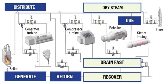
Figure 1. A steam system has four stages: generate, distribute, use and return of recoverable energy. Equipment performs best with dry steam and when condensate is drained quickly. Recovered energy reduces boiler load
How is steam used?
Steam has four stages, generation, distribution, use and return (Figure 1). Once it is in the use stage, it is important to have the steam as dry as possible, to drain condensate quickly after steam’s heat has been transferred to the process, and to recover the remaining heat and treated water from the process to return it to the boiler, thereby reducing the burden on the boiler and its impact on the cost of heating and treating raw make-up water.
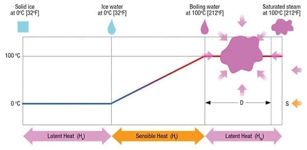
Figure 2. Heat energy is needed to change state and elevate temperature. Phase changes occur when ice becomes water and water becomes steam. Steam exits boilers with a certain amount of wetness (3–5%, not saturated)
Why is plant steam wet?
The phase changes that occur with water are shown in Figure 2 [3]. There are three phases, solid/ice, liquid/water, vapor/steam. While the temperature remains the same (0°C, 32°F) at atmospheric condition when converting ice to water at the point of freezing, it takes a certain amount of “latent” heat energy to change a mass of ice completely to water. If only some of the required heat is provided for a phase change, there would still be bits of ice in the subject mass — but the temperature remains the same (amount of added heat is unclear or hidden).
Once the full ice mass has been converted to liquid, theoretically it is now water at freezing temperature, and it is no longer ice. This ice-cold water is unsaturated — it has ability to absorb heat and still remain in a completely liquid state up until water’s saturation temperature, also known as its boiling point (100°C, 212°F). While adding heat between the point of ice water and boiling, each increase of heat raises the water’s temperature. It is why this region’s heat is known as “sensible.” By recording its temperature and mass, it is possible to mathematically calculate or sense the total amount of heat in the not-yet-saturated (unsaturated) water.
Once water is saturated, adding heat converts some of its molecules to steam — up until the point known as “saturated” steam, when all molecules have been converted to vapor. However, during this phase between saturated water and saturated steam, it is not clear exactly how much heat has been added because steam — wet or saturated, is formed at the same temperature as saturated water. The actual heat amount is hidden, hence the term, “latent heat.” Perhaps this is why steam is commonly referred to as saturated, when in fact, it is wet steam at saturation temperature — the same saturation temperature as both boiling water and steam.
Saturated steam from boilers?
Do boilers produce saturated steam? The direct answer is, “no.” Boiler steam has 3–5% wetness caused by water adhering to the outside of the steam bubbles as they break through the surface of water while exiting the boiler. There are methods that can be used to improve the quality of exiting steam, but even with those, the steam is not 100% dry and also experiences some heat loss during the distribution stage [4].
Once wet steam is produced, it can be passed through a superheater, which removes all wetness while crossing over the saturated steam threshold, and then increases its temperature, volume and total heat content. Superheated steam has a low specific heat content, so commonly its benefit is realized when obtaining high temperature or dryness, not added heat. Typical uses are for high process temperature demand, or to drive turbines.
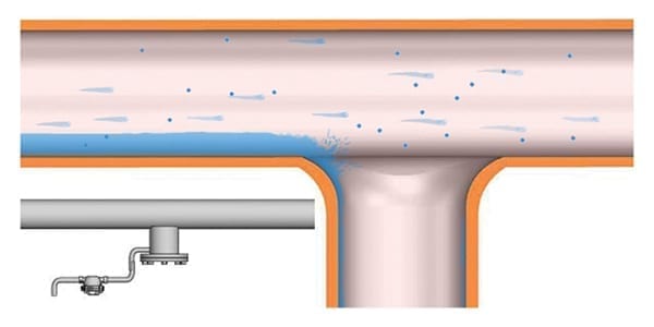
Figure 3. Steam contains condensate, both entrained in vapor, and disentrained flowing along the bottom of the pipe as a liquid stream. Only already disentrained condensate is removed through condensate discharge locations
Distributed steam is key
When discussing steam distribution, the topic invariably leads to the importance of mitigating against water hammer. While such avoidance is critical to safe operation, it is only part of the story [2].
Water hammer examples normally only show the liquid condensate that has already been disentrained from the steam flow. It rarely considers the wet steam droplets that are part of a wet steam mixture, and how adversely those droplets can create issues that affect operational efficiency and reliability (Figure 3) [5]. A review of how wet steam reduces reliability of specific equipment is provided later, but first additional information about steam wetness is provided. The specific enthalpy of steam can be calculated using Equation (1):
hg = hf + ( D x hfg) (1)
Where:
hg = Steam total heat
hf = Sensible heat
hfg = Latent heat
D = Steam dryness, %
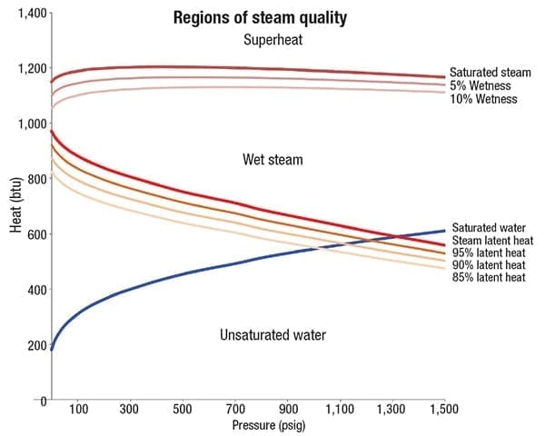
Figure 4. Entrainment affects the amount of latent heat per unit of mass that is provided to equipment. 10% or 15% entrainment reflects a significant decrease in heat capability, and can create reliability problems in certain equipment
Consider Figure 4, which shows the regions of steam quality and heat values. The dark blue line represents saturated water, with the area under this line representing the region of unsaturated water. This water line demonstrates that as pressure increases up to 10.35 MPa (1,500 psig), additional heat must be added to reach boiling.
The red line represents the latent heat — the heat of steam that is used for most process applications. Latent heat decreases in the graph as the pressure increases. The higher the pressure, the less steam heat is available. The mustard-colored lines under the steam latent heat line are most important because they demonstrate the reduction in latent heat for a given percentage of wetness — up to a 15% wet steam mixture. Some applications may have a wet steam slurry of 30% condensate, so 15% wet steam is a real possibility to be considered, particularly at the “wet end” of a plant.
The brown line represents the total heat of steam, and the two lighter lines directly beneath it show how the total heat changes when steam is wet. Heat added above the brown line shows a superheat region [6]. While total heat is required to produce steam, only latent heat is used in most steam-equipment applications.
Is letdown steam saturated?
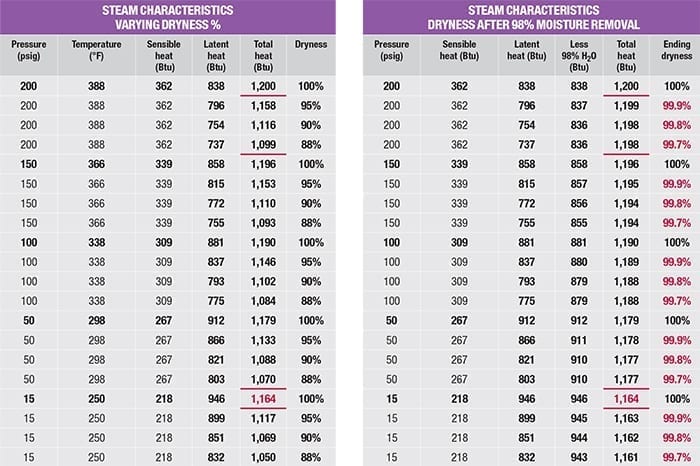
A common belief is that letting down steam from a higher pressure to a lower pressure through valves can create saturated or even superheated steam. While relatively easy to demonstrate from a theoretical standpoint, such calculations may be unrealistic. Consider the two tables shown as Figure 5. The table on the left lists the total heat of steam at 200 psig for 5, 10 and 12% wetness (95, 90 and 88% dryness), as well as the required total heat for saturated steam at 15 psig. Even the 200 psig steam with only 5% wetness (1,158 Btu) is not sufficient to create saturated steam at 15 psig (1,164 Btu). In real applications, steam can have much more wetness due to poor trapping that does not remove sufficient disentrained water, insulation inefficiency and other heat-robbing aspects that naturally occur in pipe systems, such as flanges acting as a heat sink or normal convection. This is why plant steam — if not superheated — is wet.
How to improve steam quality
The right-hand chart of Figure 5 shows the effects of 98% moisture separation from a steam flow with entrained moisture. All of the steam quality values exiting the separation stage approach dry steam territory, with estimated values of 99.7 to 99.9% dryness.
There are several key requirements to achieve high dryness, such as proper trapping, high percentage of “good” condition steam traps, and operation within a separator’s specified required range for flow, velocity and pressure. However, when properly designed and installed, separation can significantly enhance equipment operational reliability. It is important to understand that moisture removal does not increase energy efficiency, but rather improves heat transfer and equipment reliability.
The final dryness of steam, after moisture removal, can be calculated using Equation (2):
De = Do /[1 – S(1 – Do)] (2)
Where:
De = Steam dryness after separation, %
Do = Steam dryness before separation, %
S = Moisture separation, %
Mechanical separation
Collecting legs and their steam traps remove condensate that has already been disentrained from flowing steam. A useful way to remove condensate that is still entrained in steam flow is to install mechanical separation. There are four key characteristics of separator design: physical impediments, impingement, flow velocity and directional changes.
Physical impediments can consist of ridges, walls or baffles. Impingement may be aided by including rough surfaces, flow velocity can be increased by pushing steam through small openings and incorporating a cyclonic design, and directional changes should twist and ideally reverse the flow path [7].
An example of a high-velocity steam separator incorporating these four characteristics and their interactions to accomplish efficient separation is shown in Figure 6.
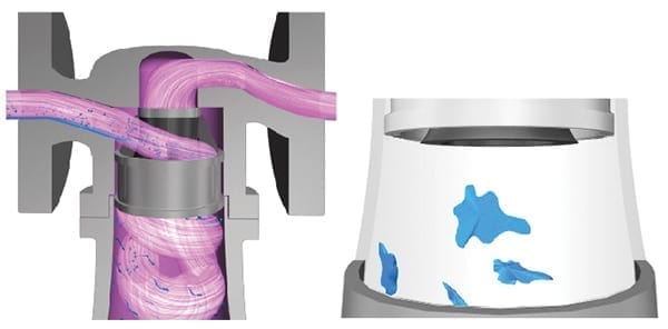
Figure 6. High-velocity cyclone separators can remove 98% wetness from steam provided that the flow velocity and wetness percentage are within the separator’s required operating specifications
Some important considerations when selecting separators and achieving the separation efficiency include the steam flowrate, its velocity — to make sure the flow stays within the required range for the separator to perform to specifications, the expected condensate load to be discharged (for the purpose of selecting the steam trap to drain the condensate), and the maximum pressure drop allowed. Selecting a separator with minimal pressure drop is especially important to maintain steam pressure and its corresponding temperature. Lowering temperature unnecessarily can decrease the amount of heat that flows into certain processes, so it is key to minimize pressure drop through separators to maintain the highest temperature that can drive heat into a process.
The importance of separators
Once systems have condensate properly drained through steam traps, the use of separators can have a profoundly positive impact on various equipment.
Turbines. Turbines may be single or multi-stage (Figure 7). Regardless of the number of stages, it is important to use steam that is free from water slugs or droplets. Often, the steam quality driving turbines is less than ideal, with the result that plant operations may open bypasses or bleed valves, creating a fog zone (Figure 8). Even when such measures are implemented, turbines can experience issues with the trip and throttle valves, plating, erosion, or severe damage to the blades.
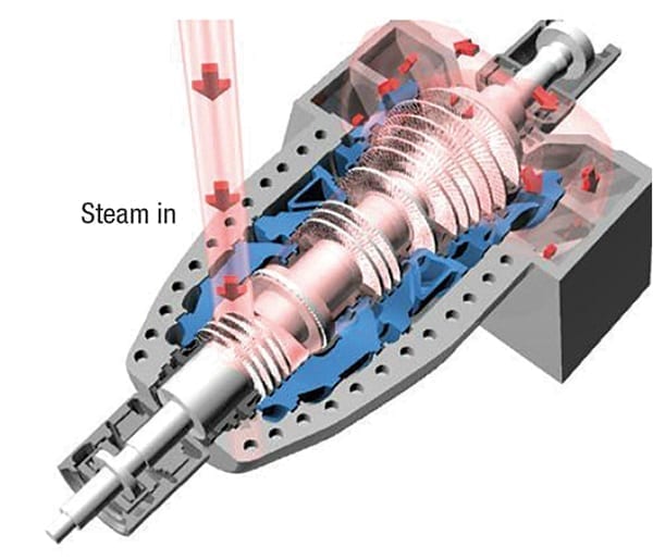
Figure 7. Steam turbines are crucial to plant operations
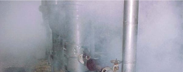
Figure 8. Steam blow in turbine areas can be avoided when using improved steam quality
Problems caused by condensate generally fall into the following two cause classifications:
1. The condensate in the steam line feeding the turbine was not properly drained through good functioning steam traps [8, 9]. This can be mitigated by implementing procedures to maintain the traps on the distribution line supplying steam to the turbine, and checking the overall drainage design to make sure that locations which pool water before, at, or after the turbine have good function steam traps installed.
2. The supply steam has significant amounts of entrained moisture. Not only does water striking a blade at high velocity create erosion, but there is also the dynamic that the blade spins at high speed. As steam is slung outward, the acceleration creates a drop in localized static pressure — causing entrained water droplets to vaporize. This action creates “moisture loss” (negative work [10]), adds to erosion, and any precipitate in the condensate will drop out of the steam and can deposit on the blades. Mechanical separation offers an excellent means to reduce or remove entrained moisture in the steam supply. Turbines experiencing frequent washdowns should have the steam trapping and steam separation systems checked for good design and operation to mitigate the frequency.
Furthermore, “The results of many tests indicate that the efficiency of a [turbine] stage is reduced by about 1% for each 1% of moisture present in the steam” [10].
This does not imply an energy efficiency benefit, as the same amount of energy must still be created at the boiler. However, moisture droplets that can cause interruptions from drag or flashing are removed, allowing the turbine to operate at optimal efficiency.
When the steam distribution line feeding the turbine is properly drained, and when steam is pulled from the top of the distribution line, then a combination drainage and separation design may resemble the example shown in Figure 9. Note that after the initial separation, the trip and throttle valve is drained, as well as the turbine casing(s), and outlet riser.
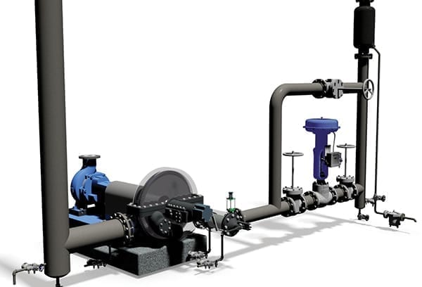
Figure 9. A turbine installation with properly drained and separated steam supply promotes reliable operation
Sufficient collecting legs and their steam traps do not always exist in the distribution line supplying steam to the turbine. This can create major issues in operating units, such as a fluid catalytic cracker (FCC). An oversized collecting leg (condensate collection bottle or CCB) and steam trap installation may provide some slug mitigation, which should be followed by a high-velocity mechanical separator to remove entrained moisture (Figure 10) [9].
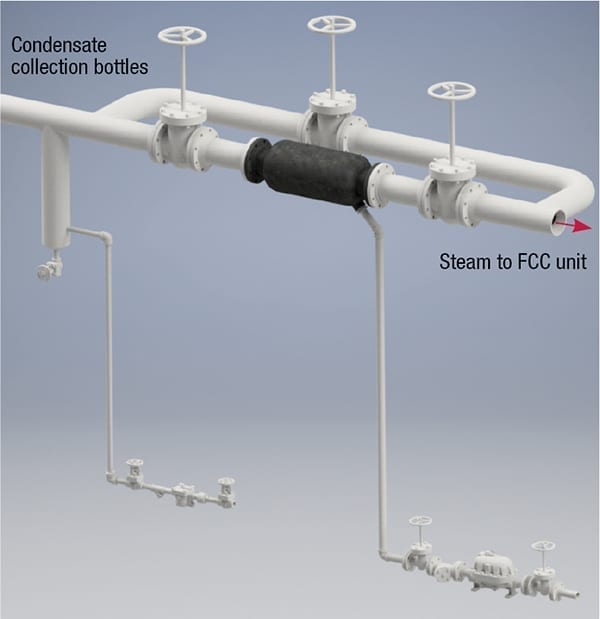
Figure 10. Poor quality steam to an FCC unit may require extraordinary measures
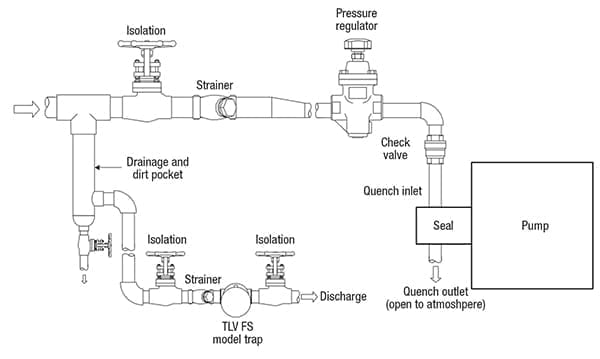
Figure 11. Trap condensate from seal steam before pressure regulating valve (PRV)
Seal steam Per API 682 Plan 62. Seal steam maintains pressure on the pump seal while providing cooling to it, but wet steam can cause premature seal failure. So, moisture should not be allowed to enter and should be removed beforehand. API 682 Plan 62 is intended to prevent water in the seal, but it is commonly misunderstood, with incorrect installation as the result. An important consideration is to make sure that the seal steam supply is trapped prior to the pressure regulating valve and that the trap does not discharge condensate into the seal itself (Figure 12). Normally, seal steam lines have small diameter, but if wet steam is being supplied to multiple pumps in a compact area — the installation of a separator before branching off to the individual pumps can disentrain condensate and optimize steam quality.
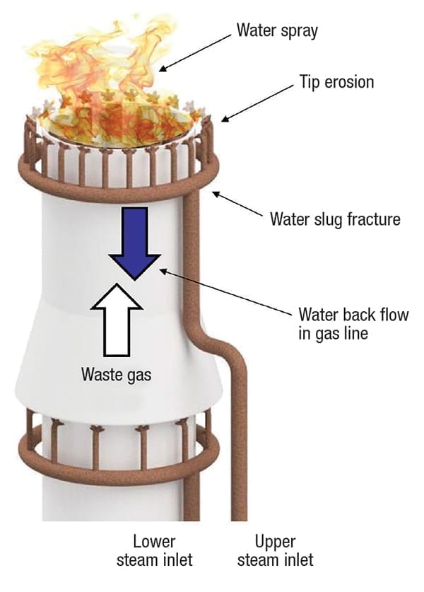
Figure 12. Multiple flare issues can be mitigated through proper drainage and operation
Flares. Flares can experience a myriad of issues, some of which are shown in Figure 12. The cause of each issue can usually be identified as either water slugs or entrained moisture in the steam supply. Again, the mitigation efforts are the same: drain condensate from the distribution line to the flare control valve station (and after), and separate wetness out of the steam supply prior to the control valve station (and steam meter) (Figure 13).
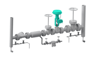
Figure 13. Proper design promotes control-valve reliability
The same basic recommendations can be made for all steam control-valve stations because steam traveling through the valve trim can reach incredibly high velocity. It is important to remove condensate and separate wetness out before the valve. Otherwise, moisture can erode the valve and vaporize during the pressure drop through the valve — causing cavitation, premature wear, and loss of control.
Ejectors and vacuum systems. The situation regarding steam quality is similar for ejectors used in vapor removal and column vacuum systems. High-velocity steam travels through the ejector at speeds of 3,000–4,000 ft/s [11], and entrained wetness creates severe erosion of the nozzle, diffuser and outlet elbow. “If moisture is present in the steam, a separator and steam trap should be used to improve steam quality to better than 99.5%” [12, 13]. Additionally, if an ejector nozzle or diffuser throat is enlarged by just 7%, the vacuum can be diminished, erratic, or broken, and the discharge temperature lowered — requiring replacement of the enlarged component [14]. A solution is to make sure the steam supply array to any vacuum system or ejector is insulated, has condensate properly drained, and wetness separated (Figure 14).
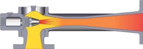
Figure 14. Separation promotes high-vacuum reliability
Waste-heat boilers and flash-recovery systems. Heating with saturated steam conveys more uniform heat and provides the shortest heating time. This is a key consideration not only for boiler-generated wet steam, but also for steam that is produced or recovered from waste heat boilers/generators, knock-out drums, or flash recovery systems. The steam quality from this type equipment can have exceptional wetness that should be separated either at the point of production, or prior to the first use station (Figure 15) [15].
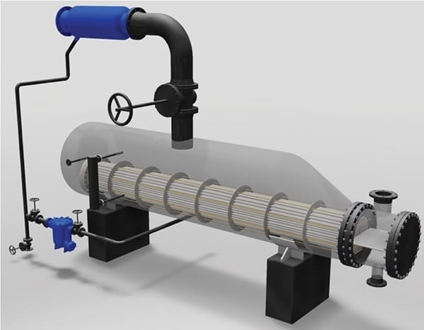
Figure 15. Waste-heat boilers, steam generators and flash-recovery installations are examples of high-wetness equipment that can benefit by using steam separators
Desuperheating steam. A desuperheating system is designed so that moisture added to superheated steam lowers the temperature to 10 or 15 degrees above saturation for the delivered steam pressure. However, its temperature sensor may be located in the top of the piping — unable to determine if the valve is discharging too much water, which flows along the bottom of the piping. Additionally, the sensor may be only a few feet away from the desuperheating valve — which can lead to erroneous readings with high velocity steam flow. As a result, it is not uncommon that the desuperheating flow creates water slugs — which can be removed by steam traps and separators for optimal downstream heating and equipment performance.
Cascading condensate-to-steam systems. When designers discharge condensate from a high-pressure steam line into the next lower steam pressure, this has the detrimental effect of increasing the burden on the steam traps to handle larger amounts of disentrained condensate. Additionally, some of that high-pressure condensate mixes with the lower pressure steam flow — thereby increasing the wetness of the already wet steam. In such systems, mechanical separation can facilitate improved equipment heating, overall performance and reliability.
Final remarks
Plant steam is wet, and its suboptimal quality adversely affects reliable production and efficiency in multiple areas. It is not possible to optimize production with suboptimal steam quality, but fortunately it can be relatively easy to improve this important heat asset.
Plants should establish a maintenance priority based on the realization that steam traps play an essential role in the quality of heat used in the production process. If steam trap health is ignored or handled on a reactive basis, the steam system may not have condensate drained properly, and this can lead to water hammer issues, as well as erosion and catastrophic damage to equipment. It also increases wetness in the steam supply, which in turn hinders process heating operations. Additionally, determine which heating equipment, turbines, and vacuum ejector systems can be enhanced by using mechanical separators to disentrain moisture from wet steam, thereby bringing its quality to near saturated levels.
Owners investing in capital projects may want to pay close attention to the design of new systems to ensure that appropriate drainage and separation equipment are included. Often it is difficult, if not relatively impossible, to correct a steam system once it is operating with lesser quality steam — with the unfortunate result that expected benchmark operation cannot be achieved. Your steam is wet, but it does not need to remain suboptimal if you implement suitable measures to improve its quality.
Acknowledgements
Special thanks to Jon Walter, Brett Bailey, and Alec Newell for their proof of the formula to calculate “Ending Dryness After Moisture Removal.” Thanks also to Drew Mohr, Justin McFarland, Terrell Moore, and TLV’s Global Marketing Communications Group for creating several of the graphics contained herein.
References
1. Risko, James R., Why Bad Things Happen to Good Steam Equipment, Chem. Eng., March 2015, pp. 50–58, www.tlv.com/global/us/articles/why-bad-things-happen-to-good-steam-equipment.html.
2. Risko, James R., Steam Trap Management: Do Something; Anything. Please!, Chem. Eng. Prog., October 2017, pp. 64–72, www.tlv.com/global/us/articles/steam-trap-management.html.
3. Change of State from Ice to Water to Steam Animation: Introduction to Condensate Recovery, TLV Co., Ltd., Kakogawa, Japan, www.tlv.com/global/us/steam-theory/introduction-to-condensate-recovery.html.
4. The Importance of Steam Dryness Fraction: “Wet Steam vs. Dry Steam,” TLV Co., Ltd., Kakogawa, Japan, www.tlv.com/global/us/steam-theory/wet-steam-dry-steam.html.
5. Separators and their Role in the Steam System: Examples of Condensate Becoming Entrained in Steam, TLV Co., Ltd., Kakogawa, Japan, www.tlv.com/global/us/steam-theory/separators.html.
6. TLV Engineering Calculator: Calculator: Superheated Steam Table, TLV Co., Ltd., Kakogawa, Japan, www.tlv.com/global/us/calculator/superheated-steam-table.html.
7. Separators and their Role in the Steam System: Separating Mechanisms, TLV Co., Ltd., Kakogawa, Japan, www.tlv.com/global/us/steam-theory/separators.html.
8. Risko, James R., Beware of the Dangers of Cold Traps, Chem. Eng. Prog., February 2013, pp. 50–53, www.tlv.com/global/us/articles/cold-steam-traps.html.
9. Risko, James R., “Allocate New Plant Focus to Steam System Design-Part 1,” Hydrocarbon Processing, January 2019, pp. 39–43, www.tlv.com/global/us/articles/plant-focus-on-steam-system-design-pt1.html
10. Avalone, Eugene A. and Baumeister, Theodore III, “Marks’ Standard Handbook for Mechanical Engineers,” 9th Ed., pp. 9–44, McGraw Hill, N.Y., 1987.
11. Lines, James R., R. T. Smith, Ejector System Troubleshooting, The International Journal of Hydrocarbon Engineering, 1997, www.graham-mfg.com/usr/pdf/TechLibVacuum/216.pdf
12. Vacuum Systems: Understanding a Key Component of a Modern Plant, “Tech Sheet 110,” Heat Exchange Institute, Cleveland, OH, p 6., www.techstreet.com/hei/standards/hei-tech-sheet-110?product_id=2002836
13. Birgenheier, David B., T. L. Butzbach, D. E. Bolt, R. K. Bhatnagar, R. E. Ojala, J. Aglitz, “Designing Steam Jet Vacuum Systems, Chem. Eng., July 1993, www.graham-mfg.com/usr/pdf/techlibvacuum/23.pdf
14. Martin, Gary R., J. R. Lines, S. W. Golden, “Understand Vacuum-System Fundamentals, Hydrocarbon Processing, October 1994, www.graham-mfg.com/usr/pdf/techlibvacuum/210.pdf.
15. Risko, James R., Handle Steam More Intelligently, Chem. Eng., November, 2006, pp. 44–49, www.tlv.com/global/us/articles/handle-steam-more-intelligently.html.
Author
 James R. Risko is president of TLV Corp. (13,901 South Lakes Dr., Charlotte, N.C. 29873; Phone: 704-597-9070; Email: risko@tlvengineering.com). The author of more than 50 articles related to steam and condensate systems, Risko is active in both the standards and technical-writing activities of the Fluid Controls Institute (FCI), and has previously served as the organization’s chairman. He is tasking with ISO for global steam trap standards, and has earned three energy-management certifications (CEM, PEM and NCSU) from the Association of Energy Engineers, N. Carolina State University and the Institute of Energy Professionals. He holds an M.B.A from Wilkes University, and two B.S. degrees, in mathematics/education and business administration/accounting, from Kutztown University. He created the “Extended Stall Chart” for heat exchangers, and co-invented the world’s first pump-trap.