Flow behavior of solid materials can have a significant impact on safety. These case studies illustrate how a better understanding of flow behavior can reduce safety risks
At least 75% of chemical process and manufacturing operations involve bulk solids in some form, whether as raw feedstock for production, as additives for chemical reactions, or as finished goods prepared for packaging. Broadly defined, bulk solids are a mixture of discrete particles, handled in various quantities. Examples include plastic pellets, salt crystals and fine powders. A material’s properties, such as particle size, moisture content and chemical composition, vary widely, introducing unique process-safety challenges that require careful consideration of the handling methods.
Safety issues often arise simply from misunderstanding how bulk solids behave. For example, it is common for process engineers to treat silos like liquid tanks, but bulk solids generate complex frictional forces, both among particles and against the containing walls, creating unpredictable flow behaviors and often misconstrued load distributions. If these effects are ignored during design, structural failure is a common result.
In another example, some fine powders are prone to dusting and segregation during handling. Their particles can remain suspended in air during the transfer of material or filling of vessels. Under these conditions, airborne particles may exceed their minimum explosible concentration (MEC), creating a serious dust explosion hazard. Equipment such as dust collectors, blenders, pulverizers and hoppers are especially susceptible if they are not properly designed and maintained.
It is clear that various solid materials — each with distinct physical or chemical properties shaped in part by their respective processes — can exhibit significantly different flow behaviors (flowability). These properties determine how solids discharge from storage, how they interact with equipment, how dust is generated and how loads develop within containment structures. When flowability is poorly understood, or ignored, the likelihood of blockages, structural failures, uncontrolled releases and combustible dust hazards increases significantly.
Using a set of case studies, this article presents the ways in which various material-flow behaviors can lead to significant safety risks in bulk-solids handling systems. Issues such as arching, ratholing, erratic discharge or sudden material collapse can threaten both process reliability and worker safety.
Flowability as a safety parameter
Before exploring these case-study scenarios, it is essential to define flowability and clarify what the term truly represents. Flowability is a collective expression of how a bulk solid responds to consolidation and applied stresses during handling and storage. It is influenced by various factors — some intrinsic to the material and others external, such as the forces imposed by the handling equipment. For that reason, flowability can be defined as a function of both the material and the equipment in which it is handled.
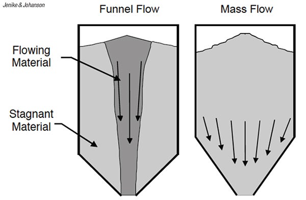
FIGURE 1. Two different flow patterns, funnel flow and mass flow, can occur in silos and hoppers
In bulk solid storage, the movement of material through a silo and hopper is typically described by two flow patterns: mass flow and funnel flow (Figure 1). In mass flow, all of the material is in motion once discharge begins. This promotes uniform residence time, eliminates stagnant regions, and reduces the potential for arching and ratholing (Figure 2). In funnel flow, material along the walls remains stationery and discharge occurs through a central flow channel in a first-in, last-out pattern. From a safety and reliability point of view, mass flow is typically preferred. However, neither flow pattern is inherently better than the other; the appropriate choice depends on the process requirements and the performance objectives of the storage system.

FIGURE 2. Examples of powder arching (left) and ratholing (right) over hopper outlets are shown here
When considering the difference between materials whose flow behaviors are considered “good” or “bad,” it is easy to imagine that a free-flowing material like dry sand should not pose any handling challenges compared to a wet clay-like material. In reality, a free-flowing material handled in a poorly designed system might still pose some significant challenges and safety risks. Systems that are not adequately designed typically result in blockages, flooding, erratic flow, equipment damage or structural failure, and in cases where operator intervention is required, the risk of injury increases significantly. The opposite is true for materials that may seem difficult-to-flow at first — if a handling system is designed correctly, most materials can still flow safely and reliably.
For a large portion of materials that are subject to evolving processes, their flow properties can change throughout the value chain. Loose, free-flowing material can quickly gain strength through compaction, causing it to resist flow. Certain factors exacerbate this phenomenon, increasing a material’s cohesive strength. These factors include moisture content, temperature and particle-size distribution, to name a few. The extent to which materials gain strength under pressure typically governs their flowability. When dealing with fine, dry powders, flowability is often dictated by the material’s ability to allow gases to move between the particles. In some cases, this may limit the flowrate of materials, while in others, it can trigger uncontrolled flooding.
Equally important is understanding how flowability is evaluated. Standardized laboratory tests and material characterization methods allow engineers to quantify flow properties and predict performance in bins, hoppers, chutes and transfer equipment. By establishing measurable parameters and interpreting them within the context of real operating conditions, engineers can move beyond assumptions and design systems that promote reliable flow — inherently minimizing safety risks. As a result, the movement of the material is predictable, the equipment functions as designed, production is stable and operators remain safe. In this sense, flowability is not just a measure of process efficiency; it is a critical parameter for maintaining safe operations.
Load distribution of stored solids
Poorly flowing materials in silos frequently result in arching and ratholing, where stable bridges or vertical channels form due to the strength of the material opposing the forces acting on it that would typically induce flow (that is, gravity). In the case of a rathole, material discharge is confined to a central flow channel while the surrounding material remains stagnant, reducing the live storage capacity and resulting in unreliable flow (Figure 2).
When arches or ratholes fail — either spontaneously or due to manual intervention — the sudden and uncontrolled collapse of material generates extreme dynamic impact loads that could exceed the predetermined static loads for which the equipment was designed. This often results in structural damage, including dents, buckling, seam splits and complete collapse. Where arches and ratholes form and collapse regularly, the erratic flow causes unpredictable pressure surges and vibrations that further exacerbate the stresses acting on the silo walls.
Effective silo design requires a thorough understanding of flow patterns and the system as a whole. Even if a silo is carefully designed, an improperly specified feeder can disrupt the intended flow, compromising performance and reliability. Sometimes this can change the flow pattern from mass flow to funnel flow, imparting significant local pressures that were not unaccounted for in the original design. For instance, adding a side discharge chute to a silo originally designed for central discharge can create uneven internal pressures (Figure 3). Without structural reassessment, this modification could cause wall deformation or even silo buckling due to the altered flow channel resulting in eccentric stresses. These phenomena highlight that the structural integrity of silos depend on the engineers’ ability to understand and predict how the materials will flow. This requires characterization of the materials flow properties — such as cohesion, friction and compressibility — to predict flow patterns and associated loads.
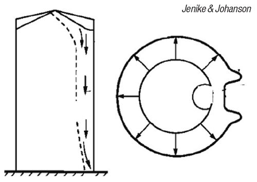
FIGURE 3. Non-uniform pressures can be caused by eccentric withdrawal of solid materials
As a reminder, material flowability is highly variable. When equipment is re-purposed for new processes or different materials, it should be re-evaluated to mitigate the risk of equipment damage and ensure worker safety.
Case study 1: flour silo
A 200-ton flour silo was designed to handle various flour products, which changed based on consumer demand and plant operations. Flour is loaded into the bin through pneumatic-conveying lines and reclaimed using a vibratory discharger to be blended into the final products. The silo was also fitted with an exhaust-air filter system, a sealed access door and a one-way pressure-relief valve.
Operators reported persistent handling problems, including ratholing and bridging. In one instance, these conditions caused flour to spill from the outlet after the seal between the silo and discharger ruptured. In another instance, the structure of the silo was compromised when the walls buckled inward (Figure 4).
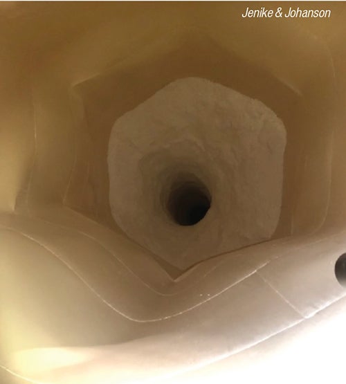
FIGURE 4. Rathole and inward buckling deformation was observed in a silo
Upon further investigation, it was determined that the flour was cohesive and, under certain conditions, could form stable arches and ratholes in the bin. This worsened in summer months, when the ambient humidity was higher, causing an increase in the moisture present within the material. When the rathole formed and failed, large volumes of flour would collapse towards the vibrating discharger, imparting high dynamic loads, which ruptured the seal. During the collapse, the falling material likely fluidized, flooding the surrounding area. The sudden expulsion of large volumes of flour likely caused a rapid drop of internal pressure in the silo, causing the walls to buckle.
Due to significant safety concerns and operational limitations, site personnel elected to replace the existing equipment with a mass-flow silo to eliminate the potential for arching and ratholing. To support the design of the new system, flow property testing was conducted on the flour. The results indicated that, although a mass-flow configuration would prevent stagnant regions, the achievable discharge rate would be limited by the flour’s low permeability, which restricts airflow through the material at the outlet. Accordingly, an air-assisted discharge system was incorporated to safely achieve the required throughput.
Moisture migration and corrosion
Corrosion is the degradation of metal caused by chemical reactions with its surrounding environment. For corrosion to occur, three conditions must be present: a metal surface, moisture and oxygen. All three are typically found inside a storage vessel.
Depending on the flow pattern, whether funnel flow or mass flow and the type of material being stored, corrosion may intensify, leading to product contamination, pinhole leaks, and, in severe cases, structural failure or even collapse. The problem can intensify in high-temperature applications handling salts or substances with low pH, as these conditions can accelerate material degradation and promote buildup and corrosion.
Case study 2: fertilizer silo
A potash storage silo that had operated for 50 years handled hot potash at temperatures ranging from 140 to 165°C, with a moisture content of 0.2% prior to loadout. Throughout its service life, the silo experienced repeated maintenance and operational issues. The hopper section alone had to be replaced five times within a decade due to increasing risks of hot material leakage and potential collapse. During a 2013 inspection, significant corrosion damage was discovered, especially at the transition between the cylindrical shell and the conical hopper (Figure 5).

FIGURE 5. Silo corrosion damage is shown here
The original silo had a 20 ft diameter cylinder, was 29 ft tall, and had a 40-deg (from vertical) conical hopper with a 2-ft outlet. Previous flow-property tests confirmed that the silo operated under funnel-flow conditions. Because of this, engineers realized that the material along the walls remained stagnant and cooled over time. As a result, moisture from the hot potash feed migrated toward the cooler wall surfaces, where it condensed. The combination of moisture and stagnant, caked potash at the silo walls created the perfect recipe for corrosion (Figure 6).
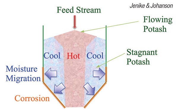
FIGURE 6. Moisture migration in a funnel-flow silo
With this understanding, engineers undertook a redesign to achieve a mass-flow silo. The upgrade involved replacing the lower cylindrical and conical hopper sections with a four-stacked hopper configuration and added thermal insulation to reduce heat loss. These modifications eliminated stagnant zones where condensation could accumulate, effectively addressing both flow-obstruction and corrosion issues. Since implementation, the silo has operated with minimal maintenance and reliability issues, and the redesign is expected to pay for itself within a few years.
Hazards in maintenance
When a silo or transfer chute experiences a no-flow condition, such as arching or bridging, it is usually treated as a process issue that must be fixed immediately. In most cases, this means operators or contractors have to step in manually to clear the blockage. If that work involves entering a confined space, the safety risks increase dramatically. The grain and agricultural industries have long documented the severe dangers and tragic outcomes that can occur when workers enter a vessel to clear a blockage.
What is often overlooked is the immense potential energy stored above a bridged outlet or a buildup hanging many feet in the air. Once that energy is released, the results can be devastating. For that reason, designing storage and handling equipment to reduce or eliminate the need for manual entry is crucial for worker safety.
Case study 3: Cement silo fatality
A flat-bottomed cement silo with a forced-extraction system had been inactive for several years due to stagnant material having caused the extractor to jam. Before returning the silo to service, the accumulated material had to be removed. The plant first hired a cement maintenance crew to clean the silo, and although they removed most of the buildup, their contract was terminated when they failed to meet the agreed upon schedule.
A second crew was then brought in to complete the job. After inspecting the site, the crew leader believed the project would be straightforward, since only a section of buildup remained (about three quarters of the silo’s height). Four workers and the crew leader were assigned to the task. During the clean-up, the leader remained on the silo floor supervising. One worker hung suspended from a platform using a jackhammer to break down the buildup; two others stood on the silo floor holding ropes to guide the platform’s rotation; and a fourth worker stayed at the top of the silo operating the platform’s electrical controls (Figure 7).
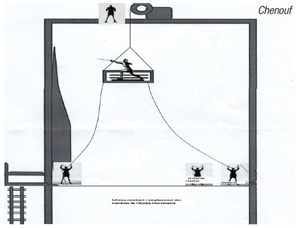
FIGURE 7. The location of the response-team members during cement silo unblocking fatality is shown. Illustration adapted from “Investigation And Analysis of a Fatal Occupational Accident,” DOI: 10.46254/AN14.20240227, N.Chenouf and W. Benhassine, IEOM Society International, USA, February 12, 2024
After approximately two hours, a large section of hardened cement was dislodged from the silo. The sudden collapse of this material resulted in the fatalities of the crew leader and one worker, while the third worker was able to escape unharmed. An investigation report that followed identified multiple contributing factors to the accident, but emphasized one central lesson: every manual intervention inside a silo must begin with a thorough onsite risk assessment to ensure that everyone involved clearly understands the hazards at play.
Dust explosions
Different organizations, such as the National Fire Protection Association (NFPA; Quincy, Mass.; www.nfpa.org), the International Organization for Standardization (ISO; Geneva, Switzerland; www.iso.org) and the International Union for Pure and Applied Chemistry (IUPAC; Rome, Italy; www.iupac.org), define dust in slightly different ways. While the specific particle-size cutoff may vary, the general idea remains the same: dust consists of fine solid particles capable of remaining suspended in air for a period of time. With that in mind, it’s easy to visualize the many industrial operations and pieces of equipment that generate or handle dust.
Equipment like dust collectors and cyclones routinely manage significant amounts of dust. Silos handling dry bulk materials can also produce significant airborne dust during filling, storage and discharge.For instance, when filling a silo where the drop heights are large or when pneumatic-conveying systems are used, dust is often produced in abundance. Additionally, if a silo is susceptible to ratholing, the sudden collapse of a rathole can fluidize fine particles, releasing large amounts of dust (Figure 8).
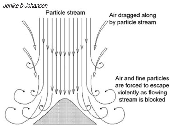
FIGURE 8: The diagram shows an example of dust generation during powder handling
The challenge with airborne dust is that even slight air currents can spread it to other parts of a facility, increasing both health and explosion risks. Dust-explosion hazards are more common than many process engineers realize. As illustrated in the dust explosion pentagon, five factors must be present for an explosion to occur: a combustible dust, oxygen, an ignition source, dispersion of the dust and confinement within an enclosure (Figure 9).
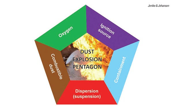
FIGURE 9. The dust-explosion pentagon shows the five necessary inputs for a dust explosion
Ignition can come from sources such as mechanical sparks from rotary valves or bucket elevators, smoldering material within a silo, or static electricity during pneumatic transfer. In addition, roughly 70% of industrial dusts are combustible, which means the danger extends well beyond obviously reactive substances, such as coal, biomass or peroxide catalysts. Even non-oxidizing materials, such as flour, polyethylene or polyvinyl chloride powders or resins, and acid powders, like ascorbic and adipic acid, can cause devastating dust explosions under the right conditions.
Case study 4: Solids transfer
At a railcar-loading station, acrylic powder was pneumatically conveyed from a silo to a railcar hopper through a metal pipeline that was adequately grounded. To improve operator efficiency, a short, flexible polyethylene hose was added to the end of the line near the railcar. Because polyethylene is an electrical insulator, that section of the pipeline could no longer be grounded.
One snowy, wet day, a dust explosion occurred that damaged two railcar hoppers. Fortunately, no one was injured by the blast. Subsequent investigation revealed that static electricity had built up in the polyethylene hose as the powder was conveyed through it. Since the hose could not dissipate this charge, and had become damp due to weather, the accumulated electrostatic energy eventually discharged as a strong brush spark, igniting the dust inside the hose. Investigators confirmed this hypothesis by repeating the transfer operation with nitrogen instead of air. Because nitrogen eliminated oxygen as a reactant, no explosion occurred.
This incident demonstrates that even seemingly harmless materials can present a dust-explosion risk, and ignition sources may arise from unexpected places. Whenever process changes involve dust, it is essential to perform a dust-hazard analysis to ensure that process safety is not overlooked.
Concluding remarks
As these case studies demonstrate, flowability governs how bulk materials store, discharge, interact with equipment and respond to environmental conditions. However, bulk-solids flow is often treated as an operational problem, rather than as a predictable consequence of material behaviors. When these behaviors are misunderstood or neglected in the design, the consequences extend beyond process inefficiencies — they can create conditions that lead to serious, and sometimes catastrophic, safety incidents.
Designing for reliable flow of bulk solid materials is therefore inseparable from designing for safety. Systems that promote predictable discharge, prevent stagnant regions, manage air-solid interactions and minimize the need for manual intervention reduce both operational disruptions and risk exposure. For the same reason, where processes are changed or equipment modified, it is equally important to re-evaluate the materials. Even the smallest modification can alter flowability and impact safe handling. For that reason characterising.a materials flowability within its process conditions and design requirements is fundamental to mitigating risk.
Edited by Scott Jenkins
Authors
 Michael Nwaeri is a project engineer with Jenike & Johanson (400 Business Park Drive, Tyngsboro, MA 01879; Phone: +1-978-649-3300; Email: mnwaeri@jenike.com; Website: www.jenike.com). Based in Mississauga, Ontario, Nwaeri has worked on bulk-solids-handling projects for the past three years that update and upgrade handling systems to ensure the reliable flow and transport of bulk solids. Nwaeri received a B.S. from McMaster University and an M.S. from the University of Toronto.
 Brandon Trevis is a project coordinator at Jenike & Johanson (same address; Email: btrevis@jenike.com), and is also located in Mississauga, Ontario. He consults on a wide range of mining projects with a focus on bulk-material handling. His work emphasizes process and design solutions that optimize material handling and storage. Trevis received his B.S. in geology from the University of the Witwatersrand in Johannesburg, South Africa.