Secondary treated wastewater from municipal plants can be a water resource for industry. Important water characteristics and treatment options are discussed
Water is a precious resource, and water quality and water pollution are important issues. Many companies and industries are trying to be “green” by reducing well-water and river-water consumption. In an effort to be more environmentally responsible, to alleviate water scarcity issues, and to be compliant with federal, state and local regulations, secondary treated wastewater from municipal water plants is currently being used in various industries to replace makeup water taken from wells, lakes and rivers. Municipal wastewater-treatment plants are frequently located near industrial water users, such as power plants, which helps to create this opportunity.
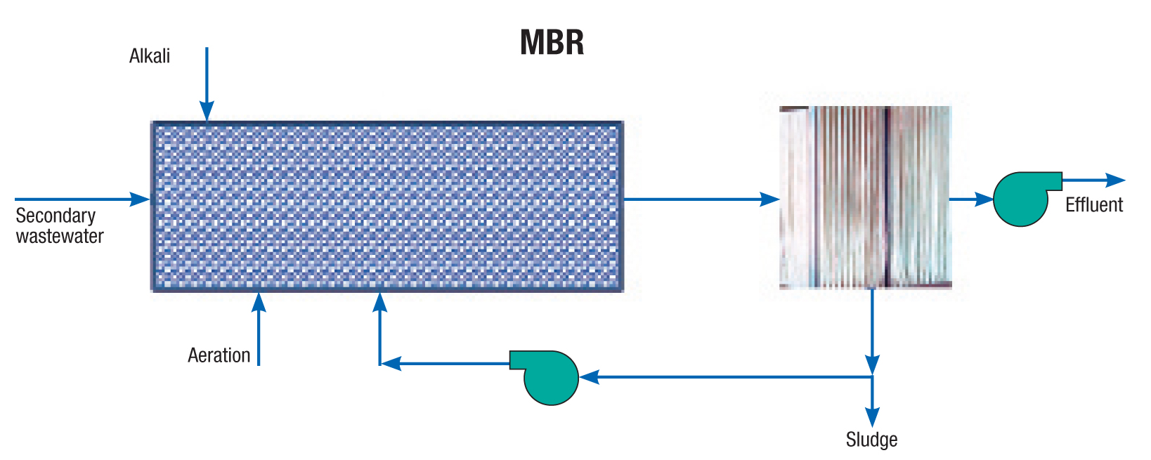
Figure 1. A typical external side-stream membrane bioreactor (MBR) is depicted here
California and Florida are the two largest users of the reclaimed water in the U.S. In 1995, the U.S. Geological Survey (USGS) study revealed that 95% of water reuse in the U.S. occurred in just four states, including Arizona, California, Florida and Texas. Now, this value is less than 90% due to increased water reuse in several other states, including Nevada, Colorado, New Mexico, Virginia, Washington, Oregon, New Jersey, Pennsylvania and New York. In response to drought, population growth and new regulations, future water reuse in California is estimated to reach 2 million acre-foot per year (ac-ft/yr) by 2020 and 3 million ac-ft/yr by 2030. California presently reuses 650,000 ac-ft/yr.
This article discusses the characteristics of secondary treated wastewater, and options for treating that water so that it is suitable for use in industrial demineralization systems and cooling towers. Relevant technologies are described and evaluated, giving advantages and disadvantages. An example and a case study are presented. Specifically, the technologies considered in this article are the membrane bioreactor (MBR), moving bed biofilm reactor (MBBR), and biological aerated filter (BAF). Considerations are included for sending secondary treated water directly to demineralization systems and cooling towers, with only chemical additives as a pre-treatment step.
The choice of the biological treatment system depends on the specific application, technical requirements, and consideration of the capital and operating expenditures (Capex and Opex). The performance and availability of the system is critical, when used for industrial plants.
Characteristics of secondary treated wastewater
Water from municipal sources, such as residential wastewater, is sent to municipal wastewater-treatment plants, which are also called publicly owned treatment works (POTWs), for primary and secondary treatment. Primary treatment includes coarse debris screed, sand and grit removal and clarification.
Secondary treatment includes attached-growth or suspended-growth biological treatment (using aeration), secondary clarification and disinfection. The primary and secondary treatments at municipal water-treatment plants remove most of the biochemical oxygen demand (BOD) and suspended solids. Typical secondary-treated-wastewater characteristics are pH 6 to 9, total suspended solids (TSS) of 35 mg/L, ammonia-N content of 35 mg/L, BOD of 25 mg/L, and chemical oxygen demand (COD) of 125 mg/L. As an example of industrial use, the typical requirements for power-plant cooling-tower makeup are pH 6.8 to 7.2 or 7.8 to 8.4, TSS 5 to 30 mg/L, ammonia-N 1–5 mg/L, and total phosphorus as phosphorus (TP–P) less than 1 to 5 mg/L depending on the cooling-tower cycles of concentration. The following is true for cooling tower makeup:
- Ammonia increases corrosion rates of copper alloys; is a nutrient for microbes; and irreversibly reacts with chlorine
- High suspended solids cause fouling
- Phosphate (PO4 3–) causes scale formation with calcium; and is a nutrient for microbes, causing biofouling
The tertiary treatment reduces the residual organic, ammonia, suspended solids and toxic chemical levels.
Guidelines for treatment levels
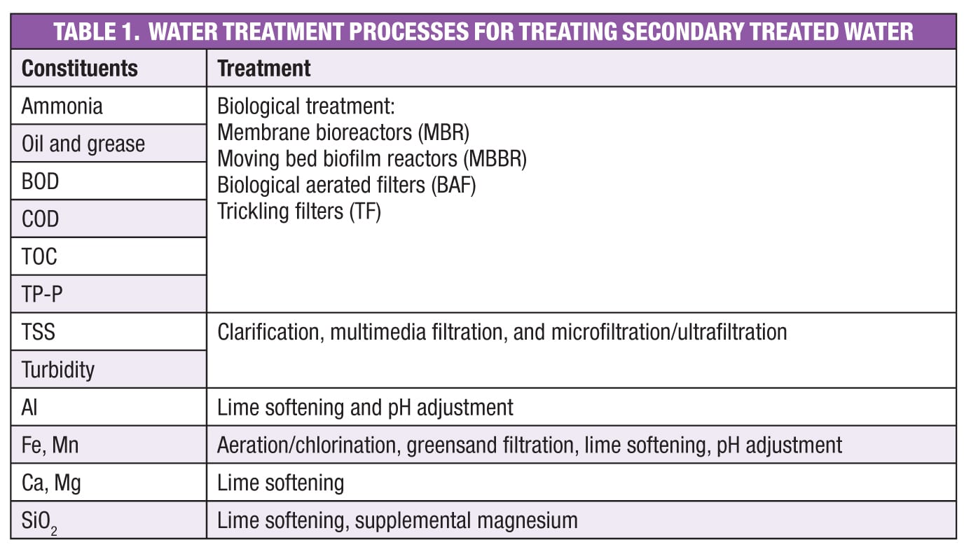
The treatment level to be obtained is set by the 2012 U.S. Environmental Protection Agency (EPA) Guidelines for Water Reuse, state regulations, and cooling tower and demineralization makeup requirements. Table 1 lists the typical constituents of secondary treated water, and the possible tertiary treatment options. Along with the capacity, constituents, and constituent-removal requirements, the temperature and pH are very important in deciding the type of technology and the size of equipment.
The sludge generated in the tertiary treatment is typically recycled to the same POTW that provided the secondary treated wastewater.
The 2012 EPA Guidelines for Water Reuse present industrial water reuse guidelines in various U.S. states. Water quality requirements for industrial reuse are lower than the unrestricted urban-use criteria because of reduced contact potential with individuals. Bacteriological quality varies from 2.2 total coliform/100 mL to 200 fecal coliform or E. coli /100 mL. Carbonaceous BOD monthly averages are 15 to 30 mg/L and TSS limits are 5 to 45 mg/L. Nutrient removal is an important step for industrial reuse, but it is not directly addressed in the EPA guidelines. To control these constituents, several biological wastewater-treatment options are discussed in this article, including MBR, MBBR and BAF.
MBRs, MBBRs and BAFs
Membrane bioreactor (MBR).A common external side-stream membrane bioreactor is shown in Figure 1. The MBR system is a combination of an activated sludge bioreactor (suspended growth) and low-pressure membrane filtration. Secondary treated wastewater from a POTW enters a grid, is screened, and is then mixed with chemicals and activated sludge in an aerated bioreactor, followed by low-pressure activated membranes for solid and liquid separation (microfiltration).
Typical mixed-liquor suspended-solids concentrations in MBR systems are 10,000–12,000 mg/L. The two types of membranes available for use in MBR include hollow-fiber and flat-sheet membranes. The MBR technology replaces clarification, disk filtration or ultrafiltration required in industrial plants. Effluent is sent to the service water tank, or plant water system, and from there to the demineralization systems and cooling water system. With an MBR, the effluent can attain NH3-N concentrations less than 1 mg/L, BOD of less than 5 mg/L, and COD of less than 50 mg/L.
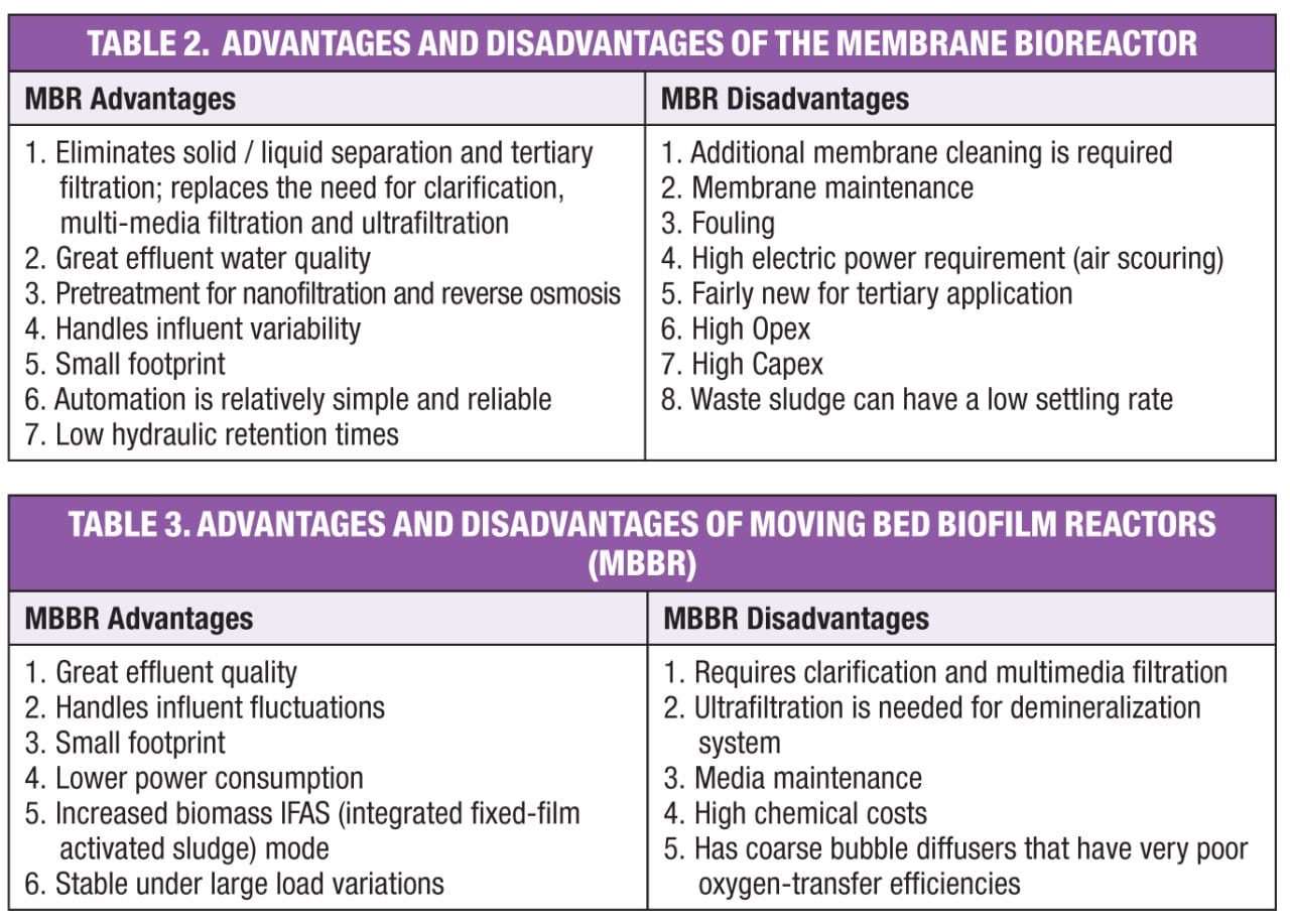
Table 2 lists the advantages and disadvantages of the MBR. Effluent water quality and ability to handle influent variability are the major reasons that many MBRs have been installed over the past 50 years.
Moving bed biofilm reactor (MBBR). A schematic of an MBBR is shown in Figure 2. Secondary treated water flows from left to right, through biofilm carrier elements or media in an aerated bioreactor. The biofilm is attached to the media. Typical carrier elements look like pretzels with inner and outer grooves and ridges: but the quantity, shapes and sizes depend on the specific application, based on water temperature, pH, capacity, constituents and required effluent quality.
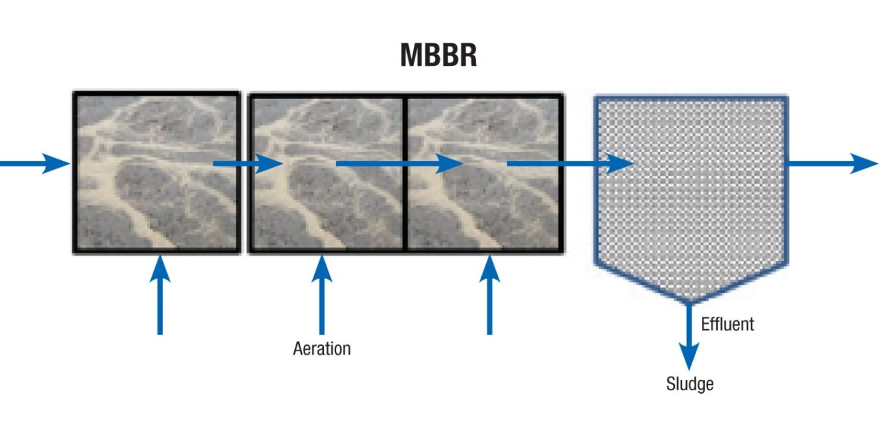
Figure 2. This schematic shows a moving bed biofilm reactor (MBBR) with water flowing from left to right through media with aeration
Activated sludge and microorganisms that are free-floating attach to the media and form biofilm. The sludge that is free-floating passes with the wastewater to a clarifier. A portion of the sludge is removed and sent back to the POTW.
The integrated fixed-film activated sludge (IFAS) variation of the MBBR process takes its name from the integration biofilm media technology inside the conventional activated sludge, where some of the sludge is recycled back to the MBBR. The IFAS/MBBR requires return activated sludge (RAS) pumps and piping. The MBBR produces an effluent with NH3-N levels of less than 1 to 3 mg/L, NO3-N less than 1 mg/L and total nitrogen (TN) less than 3 mg/L. Table 3 lists the advantages and disadvantages of the MBBR.
An example of a power-plant water balance using an MBBR/clarifier system is shown in Figure 3. The 1,000-MW combined cycle plant has three gas turbines with heat recovery steam generators (HRSG), and one steam turbine, one demineralization system and one cooling system.
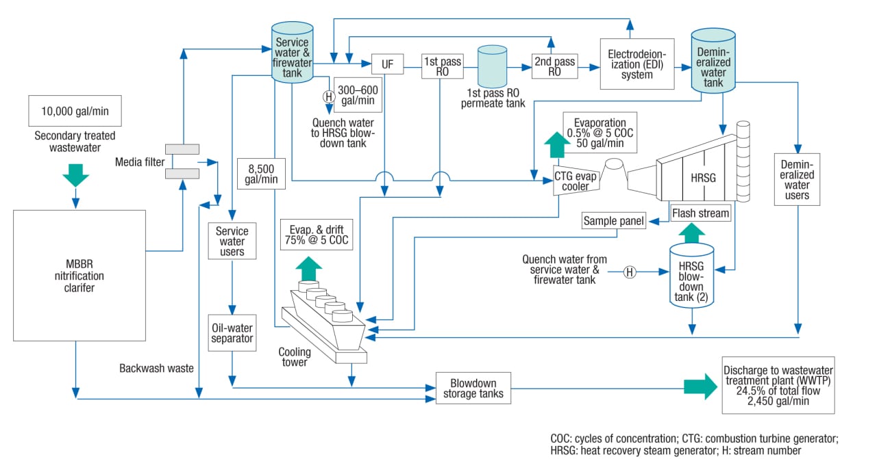
Figure 3. This is an example of a water balance for an MBBR and clarifier system
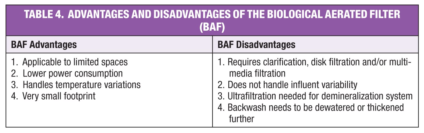
Biological aerated filter (BAF).The BAF shown in Figure 4 was introduced in the early 1980s. This system has lower operating and maintenance costs and a smaller footprint than the MBR and MMBR. The BAF is a high-flow, fixed-film, biological wastewater-treatment system that removes both suspended and dissolved organic material found in wastewater. Some vendors combined the fixed-film and dynamic media within this system.
Secondary treated wastewater from the POTW enters the bottom of a submerged, upflow-aerated biological filter made of granular media, which physically removes suspended solids and dissolved pollutants. The media provides surface area for the growth of nitrifying bacteria that assimilate ammonia. Overflow effluent is sent to the service-water or plant-water tank. Effluent quality is typically BOD 10–20 mg/L, TSS 10–20 mg/L, and NH3-N less than 3 mg/L.
The BAF is smaller than the MBR and the MBBR. Capacity of the unit can be increased by increasing the media bed height. Because of the high TSS from the BAF, disk filtration is required before sending the effluent to the service-water or plant-water tank, similar to the MBBR process shown in Figure 3. However, BAF does not handle influent BOD and TSS variations.
The major benefits and liabilities of the BAF are given in Table 4. Although BAF is applied to tertiary treated (Title 22 of the California Code of Regulations) wastewaters for ammonia removal, it is not preferred for treatment of the secondary treated wastewaters.
Alternative treatments
Of course, the bioreactors can be replaced by a clarifier, filtration and chemical addition. Although this is the lowest capital-cost system, the amount of chemicals required and operating cost make this infeasible and unsustainable in the longterm due to severe biofouling issues. The estimated chemical dosage rates compared to the MBR are as follows: corrosion-inhibitor rate doubles, mineral dispersant rate is increased 1.5 times, and the rate of sodium hypochlorite/sodium bisulfate is 10 times. Fouling is expected and annual unplanned 72-h shutdowns are anticipated for pressure washing cooling-tower fills with hydrogen peroxide or bleach. The unplanned shutdown cost will quickly pay off investments in bioreactor systems.
Case study
Figure 5 shows a rather complex application of a revamp for an existing BAF. Makeup for the demineralized water-treatment system is secondary-treated municipal wastewater. This water undergoes further processing at the industrial plant (in this example, a power plant), including biological treatment primarily to remove ammonia and disk filtration to remove suspended solids. However, the cartridge filters for the reverse osmosis and electrodeionization (RO/EDI) system were severely fouled because of submicron particles (<1µm) passing through the disk filter. An ultrafilter was proposed to be installed to protect the RO/EDI system.
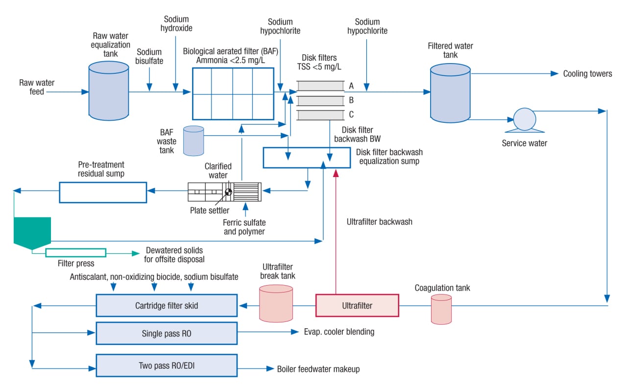
Figure 5. This rather complex application of a revamp for an existing BAF is discussed in the case study
There are two ways to handle the sludge generated from the treatment process: (1) discharging the thickened sludge to the POTW, and (2) landfilling the thickened and filter-pressed sludge. In the current case, a parallel-plate gravity-settler unit was designed to precipitate suspended solids from equalized filter backwash wastewater and the plate settler sludge was pumped back to the POTW. An additional thickener and filter press were proposed to process the plate settler sludge. The produced cake from the dewatering system can be landfilled at a nearby facility.
The proposed dewatering system utilizes a solids gravity thickener followed by a sludge conditioning tank and a filter press. The solids thickener will process residuals continuously, while the sludge conditioning tank and filter will operate on a batch basis (as needed). ■
Edited by Dorothy Lozowski
Acknowledgments
The authors thank Mike McMenus, Brian Clarke, and Brad Buecker of Kiewit Engineering and Design Co. for providing valuable comments to this article.
References
1. Morton, Robert and others, Advanced Water Treatment of Non-nitrified Secondary Effluent with Tertiary Membrane Bioreactor and Reverse Osmosis Processes, WEFTEC 2013 Conference Proceedings, 86th Annual Water Environment Federation Technical Exhibition and Conference, Chicago, October 5 to 9, 2013. http://weftec2013.conferencespot.org/55109-wefb-1.1182180/t-022-1.1185426/522-1.1185475/a-485-1.1185494
2. Bartels, Craig and others, Operational Performance and Optimization of RO Wastewater Treatment Plants, Hydranautics, Technical Papers. http://www.membranes.com/index.php?pagename=tech_papers
3. Morton, Robert, and others, Pilot Study of Advanced Treatment Processes to Recycle JWPCP Secondary Effluent, Proceedings of the Water Environment Federation, WEFTEC2011: Session 41 through Session 50, pp. 2979-2994(16). http://www.ingentaconnect.com/content/wef/wefproc/2011/00002011/00000014/art00046?crawler=true
4. U.S. Environmental Protection Agency (EPA), “Water: Effluent Guidelines,” http://water.epa.gov/scitech/wastetech/guide/
5. UN Water website, The United Nations Inter-Agency Mechanism on all Freshwater Related issues, Including Sanitation, http://www.unwater.org/statistics/en/
Authors
 Behrang (Ben) Pakzadeh is a licensed P.E. (California), and a senior process engineer with Kiewit Engineering & Design Co. (9401 Renner Blvd., Lenexa, KS 66219; Email: behrang.pakszadeh@kiewit.com; Phone: 916-689-4016). He has over 10 years of experience in power, upstream oil-and-gas, and municipal water and wastewater industries. Pakzadeh serves on the Water Environment Federation (WEF) Industrial Wastewater Committee. He has contributed over 20 presentations and technical articles for various conferences and journals. He has a Ph.D. in civil and environmental engineering from the University of Nevada – Las Vegas, an M.S. in environmental engineering from the Technical University of Denmark, and a B.S.C.E. from Sharif University of Technology (Iran).
 Raymond Eric Zbacnik is a senior process engineer with Kiewit Engineering & Design Co. (Address same as above; Email: raymond.zbacnik@kiewit.com, Phone: 913-689-4213). Zbacnik has about 40 years of chemical process engineering experience, which includes 13 years with Babcock & Wilcox, 6 years with HDR: Cummins & Barnard and 11 years with Foster Wheeler. Zbacnik holds a B.S.Ch.E. from Purdue University, and an M.E.Ch.E. from Manhattan College. He is a member of the AIChE, IChemE, ACS and AWMA.