Minor components trapped in distillation columns can react to form solids that cause major problems. The conventional responses to this situation focus upon dealing with the solids after they have become formed. A better strategy consists of preventing or minimizing the solids formation in the first place, by changing the column operating conditions.
Understanding the situation
The solids-formation problem arises during distillation when minor components react with each other under the process conditions inside the column, forming polymers or other heavy molecules that are not completely soluble in the liquid phase in certain sections of the column. The presence of these solids often leads to unpredictable vapor-liquid contact, in turn adversely affecting product quality and increasing the plant’s downtime and maintenance expenses.
In many cases, engineers approach the problem by aiming to modify trays or other column internals to deal with solids more easily, and/or by injecting additives to either inhibit the reactive species or disperse the solids. Not only are these responses usually expensive; they also do not address the underlying problem. In some cases, taking a closer look at the column operations and exploring ways in which the minor component(s) can be purged out of the process will produce better results.
The principles that affect component trapping in distillation columns has been described in much detail by Kister [1]. That reference also summarizes numerous experiences in diagnosing and eliminating such problems at chemical-process plants. Here, we discuss one such experience in detail.
The process
During final stages of adiponitrile (ADN) production, a low-boiler stripper (LBS) column removes components having relatively low boiling points, such as succinonitrile (SN) and acrylonitrile (AN), from the crude ADN stream. These low-boilers are taken out in the overhead distillate stream; the bottoms stream, containing mainly product ADN with traces of low-boiling impurities and other, higher, boilers, goes to further purification. The column operates under vacuum to minimize thermal degradation of the product. The column internals consist of structured-packing beds, above and below the feed point.
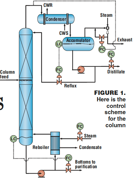
Figure 1 describes the basic control scheme for the column. The setpoint for the distillate flowrate is selected by the operator; the reflux flowrate is set by the liquid level in the overhead accumulator; steam flow is set by the operator as a function of the column feedrate; the bottoms flow is determined by the bottoms level; and the column pressure control is achieved by vacuum jet ejectors. There is no temperature control on this column.
The problem
This column had a history of operational problems, and its runtime was limited by severe fouling due to polymer formation in the packed section above the feed point. When clean, the column was able to deliver on-spec product, with minimum product loss in the overhead distillate stream. But even when the column was essentially clean (namely, soon after its startup following a cleaning), the pressure would slowly start to build up, and eventually develop into a process upset that would last several hours. Once the column had “burped” (that is, once the pressure increase had relieved itself, either by causing the liquid phase to rise abnormally or by a cooldown of the column), the operating conditions returned to normal and the column ran well until the next episode occurred.
The frequency and severity of these events was predictable. Following about six months of operation after column cleaning, these burping episodes would get worse — and became accompanied by severe flooding that increased the product loss in the distillate stream; finally, the column could no longer make on-spec products. It had to be shut down once a year for cleaning and for replacement of the packing, which resulted in lost production and raised the maintenance costs.
Inspection of the column during shutdowns showed large sections of the structured packing to be completely plugged with foulant. It was the gradual buildup of the polymer, and the subsequent pluggage of the packing, that caused the loss in separation efficiency.
An initial proposed remedy
In an effort to eliminate the problem, a team of experts evaluated a proposal that would modify the column internals so as to facilitate easier exit of the solids and reduce the cost imposed by the fouling. The team considered various structured-packing configurations, and the design that evolved represented a compromise between (1) achieving the separation required for meeting the product specifications and (2) being able to move the solids out when fouling started.
During this search for a new design, the team had noted that the version to be replaced had some inherently undesirable features. One in particular was the combination of tall beds with an absence of liquid redistributors; this combination posed a strong likelihood of liquid maldistribution and, therefore, the creation of pockets of stagnant liquid that could form sites for fouling.
Underlying the team’s diagnosis and proposed remedy was a strong belief that the process fouling in the column was due to inadequate or less-than-efficient contact between the vapor and liquid phases. So, the rationale for modifying the column internals was that the improvement in the contact between vapor and liquid would increase the separation efficiency, thereby improve the overall column operation and, hence, lessen the fouling.
An alternate diagnosis
Before the team’s proposal was acted upon, however, a different line of reasoning emerged. As it happened, the internals of this column had already been modified on more than one occasion previously; therefore, the expectation that yet another modification would lead, by some sort of evolutionary optimization, to an optimal solution seemed unrealistic. Furthermore, if liquid maldistribution or vapor-bypassing were the real problem, this new line of reasoning went, then the column operation and its inability to achieve the desired separation should be affected consistently, not just in the episodic manner observed. Therefore, the outcome from modifying the internals to improve the contact efficiency and minimize the fouling problem was highly uncertain, and had low probability for success.
Meanwhile, examination of the structured packing during one of the maintenance shutdowns showed signatures of fouling products that were characteristic of nitrile process chemistries used in other process units. Chemical analysis of the foulant confirmed that the fouling in the top section was dominated by cyanide-type polymerization. This type of polymerization leads to solids resembling coffee grounds; and when exposed to high temperatures, they tend to develop a black, tarry-looking surface. This polymerization reaction is autocatalytic — once polymerization is initiated, the rate of reaction rises rapidly. Higher temperatures also raise the rates.
Though the column operated under vacuum, the conditions within it happened to be quite conducive to chemical reaction. The discovery of the cyanide-type polymers pointed to the presence of a compound that participated, directly or indirectly, in reactions to form the polymer. It seemed plausible that the succinonitrile was this compound, for reasons given below.
The complications that were assumed to be due to this presence of SN were consistent with the rationale employed to control the column: the established operating procedure aimed to control the distillate flowrate, in order to minimize the product loss. Now, SN and ADN happen to be relatively close-boiling components, so it was not easy to achieve the dual goals of separating SN from ADN and minimizing ADN in the distillate stream without also trapping some SN inside the column. Under the conditions inside the column, SN decomposed into AN and hydrogen cyanide (HCN). The HCN, being the lighter molecule, would tend to become purged via the overhead product. But in view of HCN’s propensity to react, operators would find it virtually impossible to stop the polymerization reaction, once it was initiated,
The only way SN concentration inside the column could decrease was during process upset. As the concentration of SN increased and the aforementioned products of SN decomposition (lighter ends) could not leave the column, the operation became unstable and the pressure rose, eventually leading to a process upset. Once the column had burped, and the operation returned to normal, the process of SN accumulation started again. The situation only became worse with time, until the polymer growth completely obstructed the path for vapor and liquid, making it impossible to run the column and produce on-spec products.
Under this second diagnosis, if the column operating conditions could be modified to provide a path to purge more SN, a major source of process fouling could be reduced. Simulation studies showed that it was possible to significantly reduce the SN concentration inside the column by simply increasing the overhead distillate flow, thereby reducing the rate of fouling and increasing the column run-time
Steady-state simulations
Because the physical process of a component becoming trapped and accumulating inside a column is inherently an unsteady process, a steady-state analysis of the process would admittedly seem to be meaningless. In fact, however, a steady-state process simulation can serve as a screening tool to identify the inherent characteristics and tendencies of a process system; for example, with respect to the possibility of trapped components.
Accordingly, such a simulation was made for the process shown in Figure 1. In this simulation, the reboiler heat duty and overhead distillate flowrate were specified by the user. The column tray efficiencies were adjusted to match the steady-state process simulation results with the plant operating data and column temperature profile.
Figure 2 shows the resulting vapor-phase composition profile for SN and ADN inside the column. The horizontal axis, corresponding to the tray numbers, represents the height within the column; the top of the column is at the left. (The designation MS_SN** identifies a proprietary nitrile compound which served in the study as a proxy for SN.) The simulation results matched well with actual plant operation, with very small amount of product ADN in the distillate stream, and small amounts of SN purged via the distillate and bottoms.
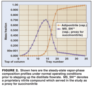
The key point observed was the “bubble” of high SN concentration that remained trapped inside the column under the normal operating conditions, and thus provided a steady source of foulant species. In Figure 2, the location of the peak in the SN bubble, slightly above the midpoint of the column, corresponded well with the region of worst fouling in the plant column.
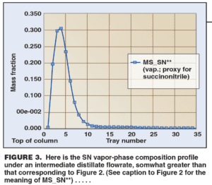
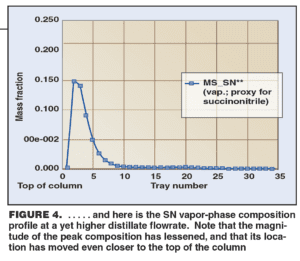
The simulation confirmed that as the distillate flowrate was increased, the SN was purged more thoroughly. The vapor-phase composition profile for SN inside the column showed that the bubble shifted upwards in the column as the distillate flow was increased (Figures 3 and 4). Correspondingly, the peak SN concentration also dropped from about 70 wt. % in Figure 2 to about 30% at an intermediate distillate flowrate (Figure 3) and to about 15% at high distillate flowrate (Figure 4).
Based on these studies made using the steady-state process model, the engineers recommended that the column be operated at a higher distillate flow immediately after startup following a column cleanup. This change required no additional capital expenditure, and it could be implemented immediately. Its effectiveness was verified within a short period of time, and the column did not exhibit the pressure rise and the burp operation observed in the past.
Applying the results elsewhere
As was the case with this ADN-purification column, symptoms of problems due to trapped components often show up in episodes that tend to be more or less repeatable with varying frequency. That frequency depends upon a number of factors, among them the column operating parameters, such as feed flowrates, reflux rates and boilup rates, and the operating conditions, such as pressure, temperature, and changes to equipment configuration.
In many cases, the real challenge to the engineer lies in understanding the type and the nature of the components that are actually getting trapped. Unintended and unrecognized reaction systems are often silent contributors to such problems and can be extremely difficult to diagnose and correct due to the non-stationary process behavior.
One class of reaction systems involves unwanted components that form because of interaction of the process streams with additives intended to enhance performance, such as antifoams, inhibitors and dispersants. Too, changes in the concentration of minor components due to variations in catalyst performance, reaction selectivity, and other parameters can trigger synthesis reactions.
Symptoms of unwanted reactions become harder to diagnose if there is added time-delay or transport lag between the reaction section of the plant and the (downstream) purification column where the problem shows up. Good knowledge of the process chemistry and access to analytical development tools can provide useful insights into the specific nature of the problem and may offer ways to reduce its impact or, in some case, completely eliminate it.
Edited by Nicholas P. Chopey
References
1. Kister, H.Z., Component Trapping in Distillation Towers: Causes, Symptoms, and Cures, Chem. Eng. Prog., Vol. 100, No. 8, pp. 22-33, August 2004.