Areas of recent activity for pressure-relief systems include new calculation methods and updates to existing codes and standards. Included here is an overview of recent developments and a look at the results from a recent study of pressure-relief system deficiencies and solutions
The process safety field is constantly changing and evolving, so it is important to periodically assess new developments that affect each of the various types of safety equipment. Pressure relief and flare systems are examples of equipment systems that have experienced recent and ongoing changes. This article focuses primarily on three areas of activity in pressure-relief systems: new calculation methods; updates to regulatory codes and standards; and lessons learned from safety events at chemical process industries (CPI) facilities. To illustrate potential problems associated with pressure-relief systems and possible mitigation options, the article also discusses the findings from a study, conducted by the authors’ employer, of pressure-relief equipment at a petrochemical facility.
New calculation methods
New calculation methods are constantly being developed and enhanced to address both new and existing safety topics (for information on calculations for sizing pressure-relief valves, see “Sizing Pressure-Relief Valves” in the March issue of Chemical Engineering at www.chemengonline.com). A few examples of this for pressure-relief systems include the following:
Two-phase flow. The Design Institute for Emergency Relief Systems (DIERS) has made two-phase flow one of its main areas of focus. Over the past three decades, DIERS has spent several million dollars to investigate the two-phase vapor-liquid onset and disengagement dynamics, as well as the hydrodynamics of emergency relief systems. Of particular interest to DIERS was the prediction of two-phase flow venting and the applicability of various sizing methods for two-phase vapor-liquid flashing flow.
Runaway reactions. In addition to advancing two-phase flow modeling, DIERS has also continued to develop and improve modeling of runaway-reaction scenarios. Over the years, more sophisticated reaction models have been developed to allow more accurate prediction and modeling of runaway reactions.
Pressure relief valve (PRV) stability. New engineering analyses have been developed through American Petroleum Institute (API) research groups to further study PRV stability for cases where inlet line losses exceed 3% of set pressure (Figure 1). This research has demonstrated that PRVs can function in a stable manner with irrecoverable inlet losses greater than 3% of the set pressure. The research also provides an accepted methodology to determine and demonstrate stable operation of PRVs.
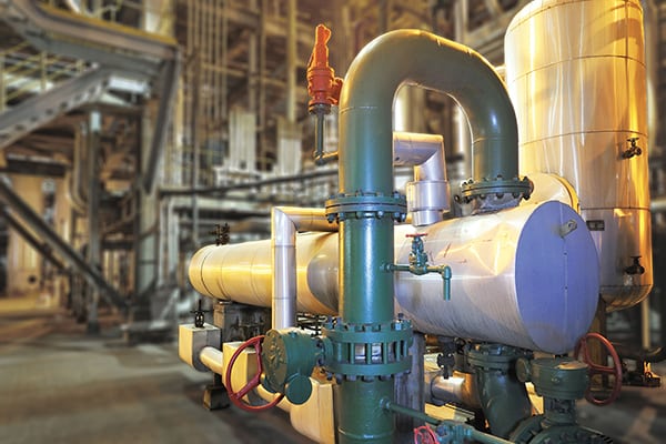
Figure 1. Pressure relief valve (PRV) stability has been an area of recent focus for API research groups
Acoustic induced vibration. Acoustic induced vibration (AIV) is generally a potential problem to piping in gas service where large amounts of high-frequency acoustic energy can be generated by a pressure-reducing device, such as a PRV. The flowrate and pressure primarily govern the amplitude of this energy transmitted through the piping system. Excitation due to AIV can lead to fatigue failure of downstream connections, with failures potentially occurring at small bore branches. It is important to consider this phenomenon when designing piping for pressure-relief systems, and when selecting appropriate piping and connections to prevent AIV from occurring.
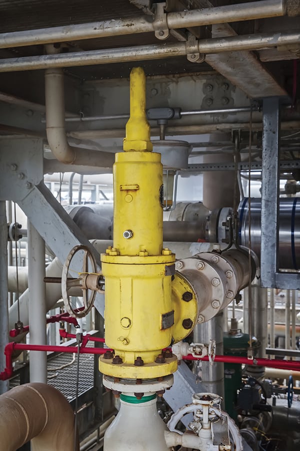
Figure 2. Regulatory codes and standards for pressure-relief devices have seen some recent updates
Regulatory code updates
Regulatory codes and standards are continuously being updated, resulting generally in both new and stricter requirements (Figure 2). The following describe several of the recent updates to codes and standards governing pressure relief systems:
API Standard 520 Part 1 [1]. This standard applies to the sizing and selection of pressure relief devices used in petroleum refineries, chemical manufacturing facilities and related industries for equipment that has a maximum allowable working pressure (MAWP) of 15 psig (103 kPag) or greater. The pressure-relief devices covered in this standard are intended to protect unfired pressure knock-out drums and related equipment against overpressure from operating events and fire contingencies.
Part 1 of this standard was most recently updated in 2014, and it includes basic definitions and information about the operational characteristics and applications of various pressure-relief devices. It also includes sizing procedures and methods based on steady-state flow of Newtonian fluids.
API Standard 520 Part 2 [2]. This standard was most recently updated in 2015, and was also promoted from a Recommended Practice to a Standard. It covers methods of installation for pressure-relief devices in gas, vapor, steam, two-phase, and incompressible fluid service.
API Standard 521 [3]. This standard was most recently updated in 2014. It provides guidelines for a number of tasks, including evaluating the principal causes of overpressure, determining individual relieving rates and selecting and designing disposal systems. These would include such component parts as piping, vessels, flares and vent stacks.
API Standard 2000. This standard covers the normal and emergency vapor-venting requirements for above-ground liquid petroleum or petroleum-products storage tanks and aboveground and underground refrigerated storage tanks designed for operation at pressures from full vacuum through 103.4 kPag (15 psig). It was updated in 2014, and discusses the causes of overpressure and vacuum, as well as the determination of venting requirements, the means of venting, selection and installation of venting devices, and testing and marking of relief devices.
This standard applies to tanks containing petroleum and petroleum products, but it can also be applied to tanks containing other liquids. However, it is necessary to use sound engineering analysis and judgment whenever this standard is applied to other liquids. This standard does not apply to external floating-roof tanks.
National emphasis programs. The U.S. Occupational Safety and Health Administration (OSHA; Washington, D.C.; www.osha.gov) Refinery National Emphasis Program and the Process Safety Management (PSM) Covered Chemical Facilities National Emphasis Program included a focus on ensuring that pressure-relief systems design documentation is kept up-to-date and accurate.
Safety incidents
Safety incidents experienced in plant operation have led the industry to rethink certain assumptions used in process safety, such as which pressure-relief scenarios are considered credible. Some examples of these incidents include the following:
Sonat Exploration Co. On March 4, 1998, a catastrophic vessel failure and fire occurred at a facility owned by Sonat Exploration in Louisiana. Four workers who were near the vessel were killed, and the facility sustained significant damage. The vessel lacked a pressure-relief system and ruptured due to overpressurization during startup. The rupture released flammable material, which ignited.
First Chemical Corp. On October 13, 2002, a violent explosion occurred in a chemical distillation tower at First Chemical in Pascagoula, Miss., sending heavy debris over a wide area. Three workers in the control room were injured by shattered glass. One nitrotoluene storage tank was punctured by explosion debris, igniting a fire that burned for several hours. During the incident investigation conducted by the U.S. Chemical Safety Board (CSB; www.csb.gov), it was determined that the capacity of the pressure-safety valve was inadequate to prevent overpressurization and catastrophic column failure.
BP plc. A major incident occurred at the BP refinery in Texas City, Tex. in March 2005. An explosion occurred when hydrocarbon vapors overflowed from a blowdown stack and ignited. The explosion resulted in 15 fatalities and 180 injuries. One of the contributing factors in this incident was the use of an inadequately designed blowdown drum and stack as part of the pressure relief and venting system for the raffinate splitter, which had gone through several design and operational changes and was located close to uncontrolled areas.
Goodyear. On June 10, 2008, Goodyear operators closed an isolation valve between a heat exchanger shell (ammonia-cooling side) and a PRV to replace a burst rupture disk under the PRV that provided overpressure protection. Maintenance workers replaced the rupture disk on that day; however, the closed isolation valve was not reopened.
On the morning of June 11, an operator closed a block valve isolating the ammonia pressure-control valve from the heat exchanger. The operator then connected a steam line to the process line to clean the piping. The steam flowed through the heat exchanger tubes, heated the liquid ammonia in the exchanger shell, and increased the pressure in the shell. The closed isolation and block valves prevented the increasing ammonia pressure from safely venting through either the ammonia pressure-control valve or the rupture disk and PRV. The pressure in the heat exchanger shell continued climbing until it violently ruptured, killing one operator and causing extensive damage.
At the time, John Bresland, former CSB chair, was quoted as saying, “This tragic accident is but the latest example of the destruction that can result from a lack of effective pressure-relief systems and practices.”
Williams Olefins. On June 13, 2013, a catastrophic equipment rupture, explosion and fire occurred at the Williams Olefins Plant in Geismar, La., where two Williams employees were killed as a result. The incident occurred during nonroutine operational activities that introduced heat to an offline reboiler, creating an overpressure event while the vessel was isolated from its pressure-relief device. The introduced heat increased the temperature of the liquid propane mixture confined within the reboiler shell, resulting in a dramatic pressure rise within the vessel due to liquid thermal expansion. The reboiler shell catastrophically ruptured, causing a boiling liquid expanding vapor explosion (BLEVE) and fire.
All incidents mentioned here were investigated by the CSB and represent a limited snapshot of events that were related to pressure-relief systems, as identified in the published CSB reports at www.csb.gov.
To improve a plant’s overall safety apparatus and meet the demands of the ever-changing safety world, it is necessary to address two general questions: What is the quality of the plant’s current safety systems?; and How effective are the mitigation options that are available to solve problems created by inadequate design?
Pressure-relief system study
It is an unfortunate reality that process safety can often be a victim of plant economics — sufficient time and financial resources are not always available to instantly and simultaneously address every safety issue. Because of this, it is necessary to prioritize. Formalized studies of a particular set of safety systems can offer insight about prioritization of potential safety improvements.
Presented here are the findings from a sample study of pressure relief systems that is similar to a safety audit (Figure 3). Such studies can be utilized to create a picture of where the plant stands on the whole, and enable the prioritization of pressure-relief systems that pose the greatest risks to the facility.
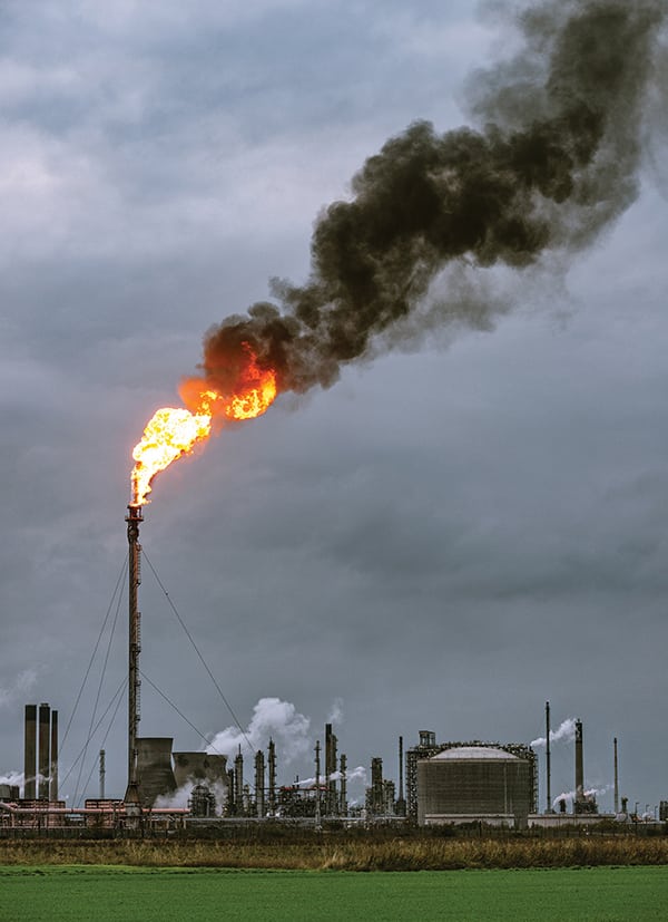
Figure 3. A recent detailed analysis of pressure-relief devices at a petrochemical facility can inform prioritization of safety projects
To help illustrate the conduct of a safety study in the context of pressure-relief systems, we describe a recent detailed analysis, carried out recently by the authors’ employer, of a process unit within a petrochemical production facility. The study analyzed all pressure-relief systems throughout the process unit and judged them to be either adequate or inadequate, according to the following typical criteria:
- Pressure-relief requirement compared to relief capacity
- Irreversible inlet-line loss (3%)
- Backpressure (10% for conventional devices, manufacturer-specific for other types, such as balanced bellows)
- Installation and code-violation issues
- Temperature concerns
Common issues
The results of the analysis of pressure-relief systems revealed a number of issues, which are discussed here, along with possible mitigation options. Of the systems and calculations analyzed, a significant number were found to be inadequate for the following reasons:
- Relief capacity: 41%
- Irreversible inlet line loss: 32%
- Backpressure: 22%
The most common factors contributing to overpressure scenarios for which the existing pressure-relief systems were inadequately sized included the following:
- Blocked outlet. This scenario was mainly due to the pressure-relief consequences not being considered during operational changes, such as increased plant throughput and increased operating temperatures
- Abnormal flow.This scenario was due to the original design missing a significant amount of manual valve operation situations, such as inadvertent opening of a control valve bypass valve
- Thermal expansion.This situation was due to failures of the original design to consider thermal expansion to be credible, even for heat exchangers with high heat duties
- Tube rupture.This was due to the original design being inconsistent regarding consideration of tube rupture as a credible source of overpressure. The original design did not consider mixing effects, such as flow of a volatile mixture to the hot side of the heat exchanger
External fires and control valve failures were found to result in very few inadequately sized pressure-relief systems, even though these two overpressure scenarios were commonly analyzed in the sample pressure-relief systems.
In the study, several factors were identified that contributed to the number of problematic pressure-relief calculations. The factors include:
- Original design work failed to consider specific pressure-relief scenarios
- Missing or conflicting sources of data
- Changes in plant throughput and operating conditions
- Changes regarding compliance and company guidelines
Approximately 70% of the pressure-relief systems analyzed were found to have an issue of some sort. Most of these issues involved interconnecting valves between equipment not being locked, or “car-sealed” open. These issues were easily resolved, but some other installation issues were not as easily mitigated. For example:
- PRVs set above MAWP
- Low points in the PRV outlet line, allowing pocketing of liquids
“Unprotected equipment” was evaluated to determine if there was an applicable overpressure scenario in the revalidation study. An equipment item could be considered to be unprotected if it does not have a free path to a pressure relief device, as defined by both API and ASME requirements. Several systemic deficiencies were identified:
- Some PRVs were set above the MAWP of the equipment they were protecting
- Pressure-relief devices on a common inlet manifold were not considered for hydraulic calculations
- Thermal-relief valves were often assumed to be adequate without proper evaluation of the applicable overpressure scenarios
- Some overpressure scenarios were not considered
- Manual/bypass valve opening was not considered
It is also worth noting that none of the existing documentation for the pressure relief devices evaluated met the current documentation guidance in API Standard 521, Section 4.7. For example, the existing documentation did not provide rationale regarding the credibility of all typical overpressure scenarios. This is a common issue in many facilities.
Mitigation options
When an existing pressure-relief system is found to have issues, there are many well-known and accepted “typical fixes.” Included here are some of the potenial issues of pressure-relief systems, along with possible mitigation strategies:
To address inadequate capacity in the pressure-relief system, possible mitigation strategies could include:
- Installation of larger PRV
- Installation of additional PRV
- Mitigation of controlling scenario (for example, fireproof insulation for an external fire scenario)
For excessive inlet pressure losses, mitigation could involve:
- Reduce the number of fittings, elbows and so on
- Use larger inlet piping
- Increase PRV blowdown
- Install a pilot relief valve
For excessive outlet pressure losses, the following actions are possible fixes:
- Reduce the number of fittings, elbows and so on
- Use larger outlet piping
- Install a bellows-relief valve
When temperatures are above the maximum allowable working temperature, plants can use fireproof insulation or water sprays for external fire scenarios. If temperatures are below the minimum design metal temperature, plants should look to select an alternate material of construction.
It should be noted that any of these “typical” fixes do not take into account cost — and indeed may be cost-prohibitive, especially for existing facilities. Therefore, prior to making any physical modification in the facility, it is worth ensuring that every design option has been considered thoroughly. Engineering design options will tend to be a fraction of the cost of any physical modification in the plant.
Practical solutions
Several mitigation options exist to address the inadequate pressure-relief system calculations, including:
Administrative changes (for example, locking a bypass valve closed). The opening of normally closed manual bypass valves around control valves contributed significantly to inadequate relief systems; particularly control valve bypass valves and steam out valves.
Locking these valves closed affects more than just the pressure-relief area sizing — with the scenario eliminated, there is no longer a need for any inlet and outlet pressure-loss calculations for that scenario.
API Standard 521 (6th edition) currently allows the use of administrative controls to mitigate or eliminate overpressure scenarios, particularly if the accumulated pressure does not exceed the corrected hydrotest. Specific guidance is given in API Standard 521 for the following scenarios:
- Closed outlets on vessels
- Inadvertent valve opening
- Check-valve leakage or failure
- Heat transfer equipment failure (tube rupture)
Locating missing data or documentation. Missing data can be a significant factor affecting pressure-relief design calculations. Conflicting data can result in inadequate pressure-relief system design as conservative assumptions are often used in cases where discrepancies exist.
The amount of information needed to meet the OSHA PSM Standard Process Safety Information (PSI) element can be considerable, and requires revalidation every five years. There is no requirement that all PSI be compiled in a single document, or that it be located in a single file. Where it is contained in various documents or locations, good practice is to compile an index of the PSI or locations, or both.
During the National Emphasis Program audits conducted by OSHA, inadequate or outdated PSI was commonly one of the most frequently cited elements. In the case of pressure-relief systems, data discrepancies can cause inefficiencies, additional costs, and most importantly, the potential for improper relief system design.
Advanced calculation methods
Improvements in computational power and software have led to increased availability of dynamic-relief sizing calculations.
Various relief scenarios can be modelled dynamically, such as the following: external fire; loss of cooling; tube rupture; and vapor breakthrough and liquid displacement
The benefits of a dynamic pressure-relief system simulation include a more accurate representation of the system at relief conditions, typically resulting in decreased pressure-relief flowrate requirements and required relief areas; and hence potentially smaller PRVs.
Additionally, dynamic simulations enable the user to model the effects of relief on upstream and downstream systems, such as the ability to compute changes in flow in and out of the system due to changes in pressure and temperature over time. Dynamic simulation can also be used to predict vessel wall failure due to fire exposure, as shown in Figure 4.
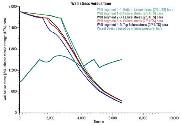
Figure 4. This graph shows an example of dynamic simulation to predict vessel-wall failure due to fire exposure
Stability analysis
PRV stability and the “3% rule” has been under scrutiny over the past several years as the subject of litigation, research and modeling. PRV instability can lead to chatter, which in turn can result in catastrophic failure of the system. It is therefore important to ensure that when the last line of defense is asked to perform, any pressure relief devices operate in a safe and stable manner. The “3% rule” remains a recommendation and not a requirement in RAGAGEP (recognized and generally accepted good engineering practice). The “rule” appears in both ASME Boiler and Pressure Vessel Code Section VIII Division I (BPVC-VIII-I) Non-Mandatory Appendix M and as a “should” in API STD 520 Part II.
API practice formed the foundation of the ASME guidance. In the past, API RP 520 Part II has allowed an “engineering analysis” to demonstrate that non-recoverable inlet pressure drop greater than 3% of the set pressure is safe, but has offered little guidance on a method.
Based on significant research and experience, the sixth edition of API 520, now a standard, includes an engineering analysis (§7.3.6) and provides valuable guidance to the user.
While the mitigation options mentioned previously may have primarily addressed pressure-relief-system capacity inadequacies, the irreversible inlet-loss inadequacies can remain a concern. The force balance method can be used to determine if the installation of a pressure-relief device will result in stable behavior, even when inlet pressure losses exceed 3%. Figure 5 provides an example of dynamic PRV stability calculations.
Additionally, the following conclusions can be drawn, based on PRV stability research: inlet and outlet piping configuration highly impacts stability; an irrecoverable inlet loss from friction has little impact.
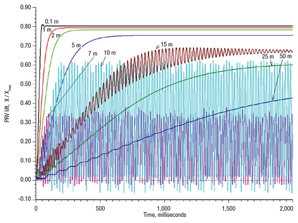
Figure 5. This graph shows an example of dynamic PRV stability calculations, with results from different lengths of inlet piping
Field changes
Despite the previous mitigation options, some inadequate relief systems may still require actual field changes. Field changes can range from relatively easy and inexpensive jobs to troublesome and exceedingly expensive jobs. Some field changes are: installation of a bellows conversion kit; installation of a larger flow area; installation of fireproof insulation or water spray; and modification of relief-valve inlet and outlet piping
Importance of documentation
Based on the authors’ experience with many pressure-relief system revalidation projects, maintaining reliable, accurate, available and maintainable pressure-relief system design documentation is an ongoing challenge for many companies. As mentioned earlier, the batch of pressure relief devices evaluated in the sample study were all lacking adequate documentation as specified in API Standard 521 (Section 4.7). It is important that updated documentation be fully compliant with these documentation requirements. When deficiencies are identified, there may not always be a simple solution to all of the safety issues. Hence, the experience and expertise of qualified safety professionals is key to identifying faults and shortcomings.
Edited by Scott Jenkins
References
1. American Petroleum Institute, “Sizing, Selection, and Installation of Pressure Relief Devices in Refineries” 9th Edition, API Standard 520 Part I, 2014.
2. American Petroleum Institute, “Sizing, Selection, and Installation of Pressure Relief Devices in Refineries” 6th Edition, API Standard 520 Part II, 2015.
3. American Petroleum Institute, “Pressure-relieving and Depressuring Systems” 6th ed., API Standard 521, 2014.
4. American Institute for Chemical Engineers and the Center for Chemical Process Safety, “Guidelines for Pressure Relief and Effluent Handling”, 1st ed., AIChE/CCPS, 1998.
5. “Maximize the Use of Your Existing Flare Structures”, IChemE Hazards XX Symposium, Manchester, United Kingdom, April 2008.
Authors
 Neil Prophet is a senior partner at ioMosaic (1900 St. James Place, Suite 700, Houston, TX 77056; Phone: 713-490-5220; Email: nprophet@iomosaic.com). Prophet brings over 20 years of experience in the field of process safety to his leading role ioMosaic’s Relief Systems consulting group. His experience includes providing project management and engineering expertise to large-scale pressure-relief and flare systems design studies for chemical, pharmaceutical and petrochemical companies worldwide. Prophet has also led numerous quantitative risk analyses, hazard identification studies and audits, and has provided litigation support for safety and relief systems issues. Prophet has authored or co-authored many industry white papers on process safety, in addition to presenting over 50 training courses and seminars covering consequence analysis and risk analysis to both operating and consulting companies. He holds a B. Eng. degree in chemical engineering and a postgraduate diploma in energy systems and environment, both from the University of Strathclyde.
 Casey Houston is a senior partner at ioMosaic (401 North 3rd Street, Suite 410, Minneapolis, MN 55401; Phone: 612-338-1669; Email: chouston@iomosaic.com). He brings over 15 years of engineering and process safety experience to his role as a leader of ioMosaic’s Relief Systems consulting group. His work is focused on managing and executing large-scale pressure-relief and flare systems design projects for reactive and non-reactive chemical, petroleum and pharmaceutical systems, as well as providing technically sound analysis and documentation for existing process and reactivity hazards. Houston is the co-author and presenter of industry whitepapers relating to pressure relief and flare systems design, effluent handling, and RAGAGEP. Houston also presents training sessions and workshops on process safety topics, such as PRV stability, pressure relief and flare systems design, and Process Safety Office, SuperChems software training. Houston holds a B.S.Ch.E. degree from Iowa State University and is a certified professional project manager.