Absorption can pull a high-value component out of an air stream and return it for reuse, often at a lower cost than destroying it
Many chemical and biological processes produce a vapor stream that is primarily air, but contains a relatively low concentration of valuable organic or inorganic compounds. Dryer exhausts, reactor vents, fermenter vents and tank-breathing vents are typical sources of such vapor streams. The chemicals that are captured by treating these vent streams can be recycled and often have significant value. Furthermore, due to emissions regulations, the chemicals in these vent streams often must be removed before discharge to the atmosphere.
A common solution is to treat the vent streams with thermal oxidation, thermal destruction or carbon adsorption. Thermal oxidation eliminates the emissions, but disposes of the product and adds operating cost. The better solution is to treat the vent stream so that the valuable material is recovered in a form that can be recycled or reused by the process plant. For a large share of these streams, this pathway is feasible, typically by utilizing an absorption process. A liquid solvent (the absorbent) is employed to absorb the valuable component out of the gas stream; clean air leaves the top of the absorber; and a second column strips the captured chemicals back out of the absorbent so that both the absorbent and the product can be reused.
Many companies with such vapor streams do not realize how cost-effective recovery by absorption can be. This article covers how the process works, why it usually beats the alternatives, how to choose the absorbent and the column internals, and two case studies that illustrate it in practice.
How absorption and stripping work
Absorption means contacting a gas with a liquid so that one or more components transfers from the gas into the liquid. The driving force is the gap between how much of the component is in the gas and how much the gas would hold in equilibrium with the liquid. As long as the liquid stays lean, the gas keeps giving the component up. In an absorber, the gas enters the bottom and flows up, while the liquid enters the top and flows down. The leanest gas meets the leanest liquid at the top, and the richest gas meets the richest liquid at the bottom, so a driving force exists at every point in the column. That countercurrent contact is what allows a single tower bring the gas down to low residual concentrations of the captured component [1, 2].
Stripping is the reverse step. The rich absorbent leaving the bottom of the absorber column is heated, usually with steam, which lowers the solubility of the captured component and drives it back into the vapor phase. The component leaves as an overhead product and the regenerated lean absorbent comes off the bottom of the stripper and returns to the absorber. Run together, the two columns form a closed loop: the absorbent circulates, the air is cleaned and the valuable material comes out concentrated.
For polar compounds, such as alcohols or acetone, water is often the choice of absorbent, because these molecules have a strong affinity for water and dissolve readily. High solubility means lower absorbent circulation to capture the same amount of material, which allows both columns to be smaller.
Carbon, oxidizers or condensation?
Three other process approaches are common, and each has disadvantages when the goal is to keep the valuable recovered compound.
Activated carbon. Activated carbon beds adsorb the chemical to be removed onto the surface of the carbon. They can be effective, but the carbon has to be regenerated to get the chemical product back, which means the addition of a steam or hot gas cycle and the associated equipment needed to run it. The carbon is a consumable that loses capacity and must be replaced over time. Beds loaded with organics also carry a real fire risk, since adsorption gives off heat, and some chemicals can create hot spots in the bed.
Oxidizers. Thermal oxidizers burn the chemical. They destroy the valuable product and burn natural gas to do it. Nothing is recovered, so the value of the chemical in the stream is gone — and there is a fuel bill on top of that.
Condensation. Simple condensation looks attractive at first, since it seemingly only involves cooling the stream and collecting the liquid. The catch is that the stream is mostly air, which does not condense. To pull the chemical out, you have to chill the entire gas flow, which creates a large cooling load. The air leaving the condenser is also still saturated with chemical vapor at whatever temperature to which the gas is cooled. By Raoult’s law, the partial pressure of the chemical above the cold liquid equals its vapor pressure at that temperature. For most volatile chemicals, that vapor pressure remains high enough at any realistic cooling temperature that significant losses to the vent are unavoidable [1]. Reaching high levels of recovery by cooling alone requires refrigeration, which is often difficult to economically justify.
Absorption sidesteps the tradeoffs of all three methodologies. It does not destroy the chemical product, it does not burn fuel, and it reaches low outlet concentrations without chilling the gas because the liquid absorbent provides the driving force instead of temperature.
Choosing the absorbent
The choice of the absorbent makes or breaks the design, and a few properties matter most. The absorbent should have a high-enough boiling point so that it does not leave with the purified air. A volatile absorbent essentially just trades one emission for another. At the same time, the absorbent should not be so heavy that it becomes viscous. This is because a viscous liquid wets the packing poorly and reduces the efficiency of mass transfer, which necessitates a taller or wider column to reach the same recovery [3].
If the absorbent is regenerated by evaporation or distillation alone, it must be possible to purify the absorbent with the available heating utilities. An absorbent that needs a process temperature higher than the available steam, or that degrades before it boils, is not workable no matter how well it absorbs.
The inlet gas almost always carries some water because atmospheric air is humid. The best absorbent has an affinity for the valuable chemical component over the water. When the absorbent also pulls in water, the two phases must be separated in a later step, or the water must be boiled off, which adds equipment and energy. This is one reason that a hydrophobic absorbent that rejects water is attractive when the target recovered chemical is not water-soluble.
Column internals and packing
Absorption columns are almost always packed rather than trayed. The feed is a vapor stream, and there is usually a blower pushing it, so the pressure drop directly impacts the fan power demand and operating cost. Packing has a much lower pressure drop than trays per stage, which keeps the operating cost down and lets a modest blower carry the load [1, 4].
For aqueous service, a structured packing with an aggressive surface texturing is an appropriate choice (Figure 1). Water has a high surface tension and does not spread across a smooth surface easily, so a packing that wets well can make a difference. Packing with an aggressively textured sheet surface spreads the high-surface-tension liquid and keeps the full area active for mass transfer, which is what an aqueous absorber needs. High-capacity packings also carry large vapor and liquid loads at low pressure drops, so the column can have a smaller diameter without sacrificing wettingor efficiency [6].
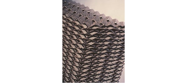
FIGURE 1. Structured packings utilize aggressive surface texturing for improved spreading in aqueous systems [See Reference 6 for further information]
For organic service, structured packing with a moderate surface texture is often the most cost-effective choice in absorber and stripper units. Unlike aqueous systems, organics typically exhibit lower surface tension and spread readily with a moderate surface texture. Certain structured-packing configurations exploit this fact by pairing a moderately textured, perforated corrugated sheet with a modified layer-interface geometry (Figure 2). The perforated and textured surface promotes uniform liquid-film distribution across the full corrugation area, maximizing the active wetted area available for mass transfer. At the layer boundary, the modified corrugation geometry reduces the abrupt directional change that liquid and vapor experience as they transition between packing layers. With some packing types, that abrupt redirection causes premature liquid accumulation at the interface, which is the primary capacity-limiting mechanism. By mitigating that buildup, high-capacity structured packings can achieve higher operating capacity while maintaining the characteristically low pressure drop typical of structured packings. This translates to a smaller diameter for the same throughput. In absorbers and strippers, where theoretical stage requirements are often modest, this combination of high capacity and low pressure drop yields a more compact and economical design [ 6].
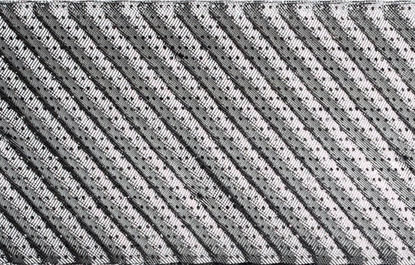
FIGURE 2. Packings like the one illustrated here utilize perforations and surface texturing to improve liquid spreading over smooth packing [See Reference 6 for further information]
Picking a packing size is an economic balance. Larger corrugation crimp sizes handle more liquid and vapor before flooding, which allows a smaller column diameter, but come at the cost of a higher height equivalent to a theoretical plate (HETP) and a taller column. Smaller corrugated or crimped packing is more efficient per foot of height, but floods sooner and requires more diameter for the same flow. The right size is the one that gives the lowest total installed cost for the loading and separation at hand, and that determination is made on a case-by-case basis [4, 6].
Case study: Ammonia recovery
A vapor feed containing ammonia, water and air enters the bottom of an absorber and meets a cool recirculating water stream flowing down (Figure 3). Water takes up the ammonia readily, so as the gas rises, its ammonia content drops until more than 99% of the ammonia has moved into the liquid. The cleaned air leaves the top of the column to the atmosphere and the ammonia-rich water leaves the bottom.
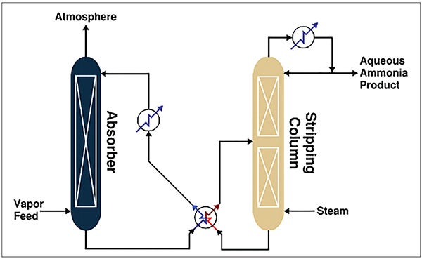
FIGURE 3. A simplified flow diagram of ammonia recovery by absorption and stripping is shown
That rich water goes to a stripping column where heat supplied by live steam injection or a reboiler drives off the ammonia. Concentrated aqueous ammonia (typically 20 wt.% NH3) leaves as the overhead product and clean water exits the bottom, returning to the absorber as regenerated absorbent. An interchanger between the hot regenerated water and the cooler absorber bottoms recovers heat and reduces steam use, which lowers operating cost.
One detail matters for fermentation and similar sources. If the feed carries carbon dioxide, as fermentation gas usually does, the CO2 follows the ammonia to the stripper overhead, where it can react and form solids that foul a conventional condenser. A direct-contact condenser avoids that issue and is the preferred choice when CO2 is present [7].
Case study: Toluene recovery
A feed vapor stream containing toluene, water and air enters the bottom of an absorber and contacts a cool recirculating stream of white oil, a highly refined mineral oil (Figure 4). The oil takes up the toluene, so as the gas rises, its toluene content drops until more than 99% is recovered into the oil. Because the oil and the toluene both have very low water solubility, almost none of the water vapor in the air is absorbed, and the rich oil stays essentially water free.
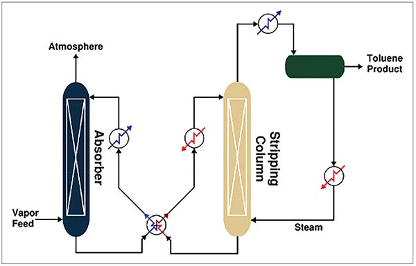
FIGURE 4. A simplified flow diagram of toluene recovery by absorption and steam stripping with oil regeneration is shown
The rich oil goes to a stripping column, where steam strips the toluene out of the oil and into the vapor. The overhead is condensed and phase-separated, forming a toluene product and an aqueous phase. That aqueous phase can be boiled to make the live steam for the stripper, which removes the need for a separate wastewater stripper.
Heat integration here uses an interchanger with a trim cooler on the hot side and a stripping column preheater on the cold side. With the oil in this example, the bottom of the column sits a little above the boiling point of water at the operating pressure (about 212°F). Because of that, the injected steam does not condense in the column, so it adds little heat to the oil via its superheat. More steam could cover the preheat duty in place of the preheater, but that means condensing and boiling recirculating water, which uses far more energy than a small trim preheater. Optimizing the configuration requires balancing feed conditions, utility constraints, desired recovery and absorbent selection, making each system unique to the application [5].
Takeaways
For air streams carrying a valuable organic chemical or ammonia, absorption followed by stripping recovers the material in a reusable form, cleans the air to low residual levels and avoids the fuel and consumable costs that come with oxidizers and carbon beds. The economics come down to a few choices: the right absorbent for the target captured chemical; tower packings that wet well and keep pressure drop low; and a heat-integration scheme matched to the utilities on site. Each of those depends on the specific stream, which is why a short feasibility study backed by a set of equilibrium data is usually the first step toward a design worth building. ■
Edited by Mary Page Bailey
Acknowledgement
All images provided by the authors
References
1. Perry, R.H. and Green, D.W., “Perry’s Chemical Engineers’ Handbook,” 9th ed. New York: McGraw-Hill, 2019.
2. Treybal, R.E., “Mass-Transfer Operations,” 3rd ed. New York: McGraw-Hill, 1980.
3. Smallwood, I.M., “Solvent Recovery Handbook.” Oxford: Blackwell Science, 1993.
4. Kister, H.Z., “Distillation Design,” New York: McGraw-Hill, 1992.
5. Ludwig, E.E., “Applied Process Design for Chemical and Petrochemical Plants,” 4th ed., A. K. Coker, Ed. Oxford: Gulf Professional Publishing, 2007.
6. Koch-Glitsch, “Structured Packing,” Bulletin KGSP-3. Wichita, Kansas: Koch-Glitsch, LP, 2025.
7. Rentsch, C. and Fox, A., From Waste to Resource: Avoiding Fouling in Ammonia Recovery, Chem. Eng., Jan. 2024.
Authors
 Tom Schafer is the co-founder and vice president at Koch Modular Process Systems (Email: thomas.schafer@kochmodular.com; Phone: 201-267-8670). He has 50 years of experience in process design, operations management, cost estimating, plant layout and sales and marketing. His specific expertise in equipment design includes distillation, heat transfer, fluid flow and process control. He holds B.S.Ch.E and M.S.Ch.E. degrees from Manhattan College.
 Brice Caldwell (Email: brice.caldwell@kochmodular.com; Phone: 201-267-8670) is a process engineer at Koch Modular Process Systems. He has nine years of experience in process engineering, with a background spanning the design and operation of chemical manufacturing facilities. He earned a B.S.Ch.E. degree from Missouri University of Science and Technology, and an M.S. degree in mechanical engineering from Georgia Institute of Technology.
 Zack Bondley is the global technical leader for packing at Koch-Glitsch (Email: zack.bondley@kes.global; Phone: 316-828-7202). He has 14 years of experience in process engineering, process design and troubleshooting mass transfer columns with a focus on packed tower systems. He earned a B.S.Ch.E degree from the University of North Dakota.