By understanding the basics of industry standards, such as API 682, plants can make great strides in controlling fugitive emissions related to equipment seals
Chemicals that unintentionally leak from equipment into the atmosphere are known as fugitive emissions. These gases and vapors include volatile organic compounds (VOCs) and greenhouse gases, such as carbon dioxide, methane and nitrous oxide.
In 1963, the U.S. Environmental Protection Agency’s (EPA; Washington, D.C.; www.epa.gov) Clean Air Act set guidelines regulating these emissions from industrial facilities into the atmosphere. Additionally, standards organizations, including the American Petroleum Institute (API; Washington, D.C.; www.api.org), have established test standards.
The guidelines set forth by the EPA, API and other organizations are intended to help lower the negative impacts of fugitive emissions on the environment and human health. Even so, fugitive emissions remain a concern and can take a significant financial toll on manufacturers in the chemical process industries (CPI), in terms of lost product, environmental remediation costs, unplanned maintenance and downtime.
Fugitive emissions can leak from various machinery sources, including valves, flanges and fittings. However, a sometimes overlooked — but nonetheless important — source of fugitive emissions can be linked to seals installed in pressurized, rotating equipment, including pumps and compressors (Figure 1). Seals are mainstays in chemical plants and petroleum refineries, and are designed to help prevent leaks and contain pressure within pumps and other rotating machinery.
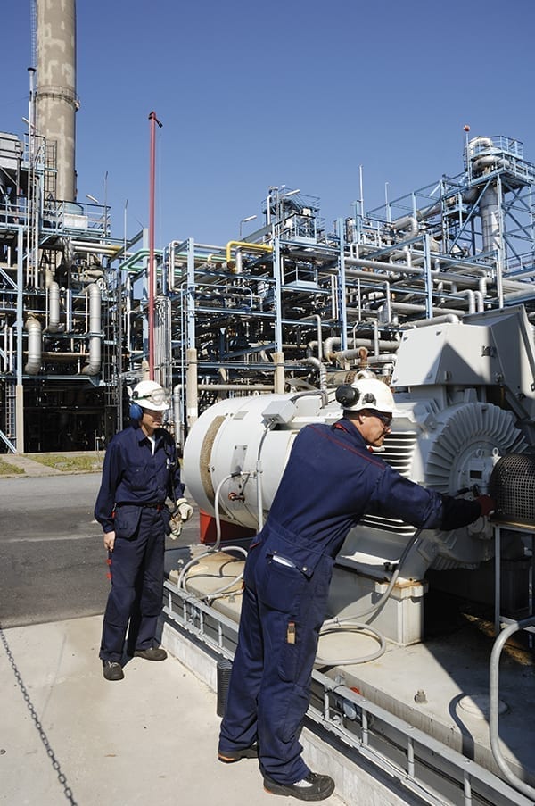
FIGURE 1. Pumps in industrial plants are an often overlooked source of fugitive emissions
While seals are intended to address fugitive emissions, one size does not fit all. This article addresses basic seal considerations for reducing the risks associated with fugitive emissions, beginning with API 682 (Pumps — Shaft Sealing Systems for Centrifugal and Rotary Pumps) and its corresponding piping plans. API 682 is the primary industry standard for hydrocarbon sealing in petroleum refineries and petrochemical plants, covering numerous arrangements and configurations for single- and dual-seal installations. The discussions in this article mainly pertain to reducing fugitive emissions with dual-seal arrangements (Figure 2), which comprise two primary seals separated by a barrier or buffer fluid.
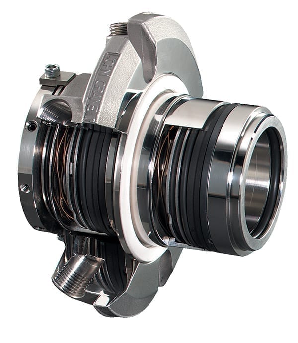
FIGURE 2. A dual-seal arrangement provides many configuration options to help reduce fugitive emissions from rotating machinery
API 682 overview
In 1994, the first edition of API 682 was published. Now in its fourth edition, API 682 sets the benchmark for hydrocarbon sealing in petroleum refineries and petrochemical plants. The standard not only dictates pump-seal space-availability requirements, but also covers the seal types, arrangements, materials, test criteria and even their support systems — as well as the technological performance criteria. The mission statement for API 682 states that it “is designed to default to the equipment types most commonly supplied that have a high probability of meeting the objective of at least three years of uninterrupted service while complying with emissions regulations.” Additionally, within the broader API 682 standard, the API Piping Plans for dual seals are primarily segregated into two varieties: unpressurized and pressurized.
For discussion purposes here, the focus will be on dual unpressurized piping plans for API Arrangement 2 seals. Arrangement 2 seals are defined as those where the buffer media pressure is lower than the seal-chamber pressure (dual unpressurized seals). The prominent piping plans for Arrangement 2 seals are API Plans 52, 72, 75 and 76. It is the expectation with any Arrangement 2 seal that the equipment be shut down and depressurized within eight hours of detected inner-seal failure.
API Plan 52
API Plan 52 is used solely for wetted contacting containment seals for both non-volatile and volatile processes. These seals require a liquid buffer system for support. An external reservoir is used to provide buffer fluid to an unpressurized dual seal’s outer seal. An internal pumping ring maintains circulation between the reservoir and outer seal. Also, the reservoir usually vents to a vapor-recovery system.
Advantages of API Plan 52 layouts include reduced overall leakage into the atmosphere. It also provides redundancy in the event of inner-seal failure. Potential solids or salts are kept in solution or suspension and the outer seal performance (visual or instrumented) is continuously monitored. However, with this configuration the buffer fluid is contaminated with process fluid. Therefore, in some processes it becomes a hazardous fluid, so disposal and personnel exposure concerns must be addressed. The buffer fluid may also be completely displaced by process fluid during inner-seal upsets, causing the containment seal to run dry and experience damage. Buffer-fluid cooling is often required to provide a more conducive environment for the containment seal faces. Operators are notified by an alarm indicating either high level or high pressure within the reservoir in the event of an inner-seal failure.
API Plan 72
Plan 72 is used with dry-running containment seals. Dry-running seals can be either contacting or non-contacting. Plan 72 specifies a gas buffer, usually nitrogen, which is used to sweep the containment cavity and push vapor leakage from the inner seal to vapor recovery or flare system. Plan 72 is used often in conjunction with either API Plan 75 or 76.
Plan 72 supplies a buffer gas from a low-pressure purge injected into the outer seal cavity, and can support both contacting and non-contacting containment seals. An uninterrupted flow of clean nitrogen or other dry gas is commonly used as a supply of inert-gas buffer. Low-pressure purge gas is injected into the outer-seal cavity. The gas-purge supply is introduced close to the outer-seal faces, while the vent and drain are positioned away from seal faces. API Plan 72 is effective in providing some cooling to the outer-seal cavity with contacting containment seals. It minimizes inner-seal air exposure and leakage to the atmosphere, as well as constantly sweeping inner-seal leakage to flare. A control panel may be installed away from equipment, because the system is not limited by flow induced from an internal circulation device, such as a pumping ring.
API Plan 75
API Plan 75 provides management of leakage of condensable gases. It is intended for use when the process sealed by the inner seal condenses at lower temperatures or is mostly in liquid form. The seal drain is located at the bottom of the outer-seal gland and routed to a reservoir below the seal. Liquid leakage is collected, and the gaseous portion is routed to the flare. This plan can offer lower initial costs when compared to Plan 52. The system can be designed to dispose of the liquid collected without operator exposure. A pressure-containing reservoir, as well as monitoring and maintenance, are required with API Plan 75.
API Plan 76
API Plan 76 is intended for use when the process sealed by the inner seal will not condense at lower temperatures or pressures. A vent is located at the top of the outer-seal gland and is routed to flare through an orifice. API 682 requires a minimum orifice diameter of 0.125 in. (3 mm) — but smaller sizes may be necessary to provide a realistic leakage-alarm point. API Plan 76 offers low maintenance and installation costs when compared with other dual-seal piping plans. However, it may be difficult to detect if liquids are present in the system. Premature wear of dry-running containment-seal faces may be encountered if inner-seal leakage contains components that condense.
Contacting and non-contacting
Although the intent of the sealing applications from the first to the fourth editions of API 682 have been largely consistent, newer materials and technologies have been incorporated into the later revisions.
Dry-contacting containment-seal designs operate in gaseous environments and use a limited amount of fluid within the seal interface film. To compensate for the lack of fluid at the sealing interface, seal manufacturers may use specially formulated grades of carbon and optimized spring loads to control face wear and interface temperatures.
Contacting dry-running containment seals provide the lowest leakage levels when sealing vapor or liquid leakage from the inner seal, but can be pressure limited (based on face wear). These seals have a finite life based on the contacting nature of the seal faces. Testing protocols should be implemented to monitor the condition of the containment seal. They are typically suitable for continuous operation in a gaseous environment with excursions in the flare or vapor-recovery system up to 40 psig, in accordance with API 682 criteria.
These seals can be either O-ring pusher mechanical-seal designs or dry-running metal-bellows configurations. Both variants are used to provide emissions control from low-specific-gravity fluids and other VOCs when used in conjunction with a suitable inner-seal design.
Non-contacting, dry-running containment seals (Figure 3) are seals where the faces are designed to intentionally create aerodynamic or hydrodynamic separating forces to sustain and maintain a specific separation gap. Non-contacting containment seals use deliberate recesses or grooves to generate hydrodynamic lift where the faces ride on a gas film during normal operation. The generated film stiffness produced from the face features provides the face lubrication and ensures that there is no face contact while in operation. The non-contacting operation of the faces eliminates rubbing frictional heat generation, allowing non-contacting containment seals to withstand much higher pressures and higher speeds than contacting containment-seal designs.
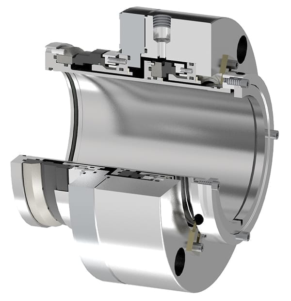
FIGURE 3. Non-contacting seals are designed to minimize heat generation due to friction, meaning that they can withstand higher pressures than contacting seal arrangements
Non-contacting dry-running containment seals are the default option in API 682 when considering a dry containment-seal system (no liquid buffer). They have a lower wear rate in operation and are more tolerant of low-dewpoint buffer gases, higher surface speeds and pressure differentials (Figure 4).
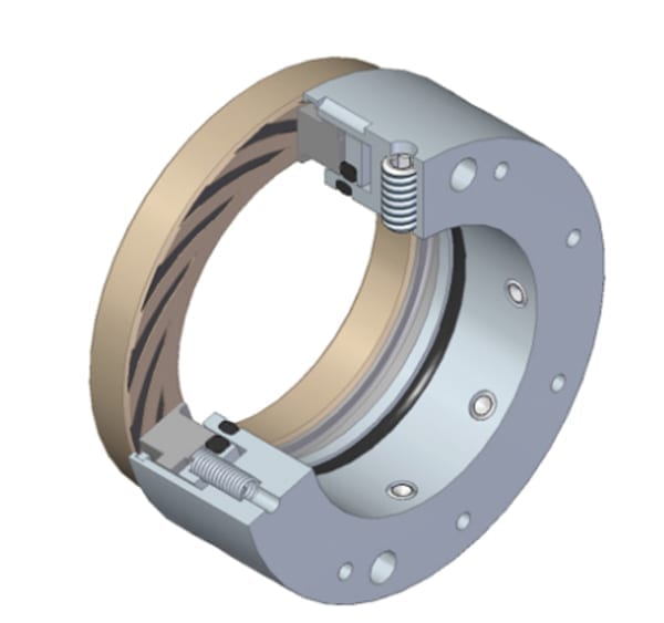
FIGURE 4. Gas-lubricated, non-contacting secondary containment seals, often applied as a component of a multiple seal cartridge, are resilient in challenging process conditions, including in the presence of low-dewpoint gases and high pressure differentials
These seals are advantageous when compared to dry-contacting containment seals in that the deliberate face separation insulates the seal from accelerated wear due to pressure excursions in the flare or vapor-recovery system. They can be instrumented to monitor temperature changes within the seal and provide an additional indication of elevated inner-seal leakage. Furthermore, they offer an extremely durable seal design and provide low cost of operation and ownership.
These sealing arrangements are among the many presented in API 682. Since the introduction of Plans 52, 72, 75 and 76 in early editions of API 682, lessons learned and additional testing activities have yielded a better understanding of the capabilities and limitations of some seal-support systems. Continued collaboration between seal manufacturers, end users and engineering contractors will provide the safest, most reliable and cost-effective sealing system for any application. As a result, these companies will continue to make positive impacts on the environment by reducing fugitive emissions. They will also reduce product waste, environmental remediation costs, unplanned maintenance and downtime.
Edited by Mary Page Bailey
Authors
 Brian Kalfrin is senior regional engineering manager at John Crane (Email: [email protected]). He has over 19 years of experience working with mechanical seals and related systems. At John Crane, his duties include design engineering oversight, analysis and recommendation formulation to address challenging applications, along with design evaluation of existing and proposed mechanical seals using finite element analysis (FEA) software. He is also responsible for training of both users and John Crane personnel in mechanical seal applications and troubleshooting. Kalfrin is a member of the Texas A&M International Pump Users Symposium Advisory Committee and the API 682 Task Force currently working on the 5th edition of the standard. He holds a B.S. in mechanical engineering from Drexel University.
Neil Slater is strategic alliance manager, Europe, Middle East and Africa (EMEA) at John Crane (Email: [email protected]). He has worked for  John Crane for the last 5 years, and his current role involves working with key end-users to deliver performance-based reliability programs that look at improving the mean time between repair (MTBR) and availability of rotating equipment across the EMEA region. His previous responsibilities with John Crane include a business development role with the company’s Vessel Seals division. Slater began his career in an apprenticeship in the pump industry and also worked with the Royal Electrical and Mechanical Engineers in the British Army.